EP1370432B1 - Systeme d'essieu - Google Patents
Systeme d'essieu Download PDFInfo
- Publication number
- EP1370432B1 EP1370432B1 EP02722239A EP02722239A EP1370432B1 EP 1370432 B1 EP1370432 B1 EP 1370432B1 EP 02722239 A EP02722239 A EP 02722239A EP 02722239 A EP02722239 A EP 02722239A EP 1370432 B1 EP1370432 B1 EP 1370432B1
- Authority
- EP
- European Patent Office
- Prior art keywords
- axle
- assembly according
- axle assembly
- axle body
- radius arms
- Prior art date
- Legal status (The legal status is an assumption and is not a legal conclusion. Google has not performed a legal analysis and makes no representation as to the accuracy of the status listed.)
- Expired - Lifetime
Links
Images
Classifications
-
- B—PERFORMING OPERATIONS; TRANSPORTING
- B60—VEHICLES IN GENERAL
- B60B—VEHICLE WHEELS; CASTORS; AXLES FOR WHEELS OR CASTORS; INCREASING WHEEL ADHESION
- B60B35/00—Axle units; Parts thereof ; Arrangements for lubrication of axles
- B60B35/02—Dead axles, i.e. not transmitting torque
- B60B35/08—Dead axles, i.e. not transmitting torque of closed hollow section
-
- B—PERFORMING OPERATIONS; TRANSPORTING
- B60—VEHICLES IN GENERAL
- B60G—VEHICLE SUSPENSION ARRANGEMENTS
- B60G9/00—Resilient suspensions of a rigid axle or axle housing for two or more wheels
- B60G9/003—Resilient suspensions of a rigid axle or axle housing for two or more wheels the axle being rigidly connected to a trailing guiding device
-
- B—PERFORMING OPERATIONS; TRANSPORTING
- B60—VEHICLES IN GENERAL
- B60G—VEHICLE SUSPENSION ARRANGEMENTS
- B60G2200/00—Indexing codes relating to suspension types
- B60G2200/30—Rigid axle suspensions
- B60G2200/31—Rigid axle suspensions with two trailing arms rigidly connected to the axle
-
- B—PERFORMING OPERATIONS; TRANSPORTING
- B60—VEHICLES IN GENERAL
- B60G—VEHICLE SUSPENSION ARRANGEMENTS
- B60G2204/00—Indexing codes related to suspensions per se or to auxiliary parts
- B60G2204/10—Mounting of suspension elements
- B60G2204/12—Mounting of springs or dampers
- B60G2204/126—Mounting of pneumatic springs
-
- B—PERFORMING OPERATIONS; TRANSPORTING
- B60—VEHICLES IN GENERAL
- B60G—VEHICLE SUSPENSION ARRANGEMENTS
- B60G2206/00—Indexing codes related to the manufacturing of suspensions: constructional features, the materials used, procedures or tools
- B60G2206/01—Constructional features of suspension elements, e.g. arms, dampers, springs
- B60G2206/012—Hollow or tubular elements
-
- B—PERFORMING OPERATIONS; TRANSPORTING
- B60—VEHICLES IN GENERAL
- B60G—VEHICLE SUSPENSION ARRANGEMENTS
- B60G2206/00—Indexing codes related to the manufacturing of suspensions: constructional features, the materials used, procedures or tools
- B60G2206/01—Constructional features of suspension elements, e.g. arms, dampers, springs
- B60G2206/10—Constructional features of arms
- B60G2206/11—Constructional features of arms the arm being a radius or track or torque or steering rod or stabiliser end link
-
- B—PERFORMING OPERATIONS; TRANSPORTING
- B60—VEHICLES IN GENERAL
- B60G—VEHICLE SUSPENSION ARRANGEMENTS
- B60G2206/00—Indexing codes related to the manufacturing of suspensions: constructional features, the materials used, procedures or tools
- B60G2206/01—Constructional features of suspension elements, e.g. arms, dampers, springs
- B60G2206/20—Constructional features of semi-rigid axles, e.g. twist beam type axles
-
- B—PERFORMING OPERATIONS; TRANSPORTING
- B60—VEHICLES IN GENERAL
- B60G—VEHICLE SUSPENSION ARRANGEMENTS
- B60G2206/00—Indexing codes related to the manufacturing of suspensions: constructional features, the materials used, procedures or tools
- B60G2206/01—Constructional features of suspension elements, e.g. arms, dampers, springs
- B60G2206/30—Constructional features of rigid axles
- B60G2206/32—Hollow cross section
-
- B—PERFORMING OPERATIONS; TRANSPORTING
- B60—VEHICLES IN GENERAL
- B60G—VEHICLE SUSPENSION ARRANGEMENTS
- B60G2206/00—Indexing codes related to the manufacturing of suspensions: constructional features, the materials used, procedures or tools
- B60G2206/01—Constructional features of suspension elements, e.g. arms, dampers, springs
- B60G2206/80—Manufacturing procedures
- B60G2206/82—Joining
- B60G2206/8201—Joining by welding
Definitions
- the invention relates to a bogie with a rigid, z. B. axle tube formed as the axle having vehicle axle, each with a guide arm on both sides of the vehicle longitudinal center plane, which at a first front end to a chassis-fixed bearing point articulated and spaced rigidly connected to the axle body, and which in the region of its first end opposite the rear end of the forms lower support of a spring element, on the upper side, the vehicle chassis is supported.
- Such a bogie is for example from the EP-A-0 806 311 of the US 56 90353 or the EP-A-0 830 960 known.
- Achsêt can z.
- a special axle tube are used, the cross-section or wall thickness is increased in the region of the connection with the separate guide arms, for example by a compression process.
- the guide arms are single substantially box-shaped with vertical side walls and floor or ceiling walls which are welded together.
- the rigid connection of the guide arm with the axle body is provided by at least partially circumferential welds, which require high precision in manufacturing and are exposed to heavy loads during use.
- Object of the present invention is to develop a bogie of the type mentioned so that the manufacturing and assembly costs and weight at low production costs are further reduced without reducing the reliability and stability of the axle.
- axle body and the two guide arms together of two in each case substantially integral and with each other along a. essentially horizontally extending parting line connected, in particular welded, mold halves exist, so that the axle body rigidly connects the two guide arms together.
- the upper axle half and the lower axle half are in this case each essentially integrally connected to two upper guide link halves or two lower guide link halves, which complement each other.
- Such shell-like mold halves can be produced inexpensively in small quantities from sheet metal with suitable pressing or forging devices with little effort.
- a bracing or welding separate control arm, for example, with the axle body and the labor-intensive joining of the guide arm of several wall elements, as required by the prior art, can be omitted.
- a weld is only for connecting the two mold halves in the region of z.
- the compression molding of the mold halves allows a weight and load optimized wall thickness distribution in the axle. So it is for example possible to increase the material thickness in the highly loaded area of the compound of the guide arm with the axle body and in less stressed areas accordingly to reduce.
- the axle assembly according to the invention thereby obtains a high rigidity and at the same time low weight.
- the rigidity of the axle assembly can be further increased with low weight, that the two mold halves together form a cavity between them. Bending and torsional moments acting on the axle unit can be absorbed particularly well in this box construction method.
- a bearing sleeve for connecting the guide link to the vehicle chassis is formed or attached to the front ends of the guide link, it is possible to use individually matched to the vehicle chassis bearing sleeves with the same geometry of the axle assembly. Next can be used in this way, different materials for the bearing sleeves and the mold halves, such as bearing sleeves made of copper alloys.
- the bearing sleeves can be attached by a welded connection particularly simple and durable to the guide arms, which at the same time the stability of the axle assembly is increased.
- the axle assembly according to the invention can be used with different types of vehicle chassis, if a plurality of through holes extending substantially perpendicular to the plane of the parting line are provided at the rear ends of the guide links in order to fasten spring elements to the guide rods.
- the spring elements are fastened in different through holes via, for example, a threaded pin. Due to the wide availability of the Achsaggregats with different Anlagenchassistypen the manufacturing costs and in particular the cost of the molds of the mold halves can be kept low.
- the shock absorber connection can be done in a conventional manner.
- a brake such as a fixed caliper disc brake, space-saving and protected
- a passage opening In this passage opening functional elements of a brake system can be accommodated without unnecessarily increasing the space in the wheel suspension.
- the stability of the axle assembly can be further increased by an annular wall is inserted into the through hole and welded to the mold halves.
- one axle journal is preferably rigidly fastened in each case in both side openings of the axle body.
- This axle journal can be pressed, for example, into the axle body designed as an axle tube and optionally welded thereto or otherwise connected to the axle aggregate Way, it is possible to use different sized journals for the same axle unit geometry.
- roller bearings are provided in both side openings of the axle body.
- the wheels can be accommodated in this embodiment via an extension of the wheel hub in the bearing unit in the axle body.
- the design of the wheels or the brake largely independent of the geometry of the axle assembly, so that it can be used variably for different vehicle types.
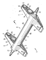
- FIGURE shows a bogie according to the invention in a schematic perspective view.
- the axle assembly 1 is composed of a lower half of the molded part 2 in the figure and an upper half of the molded part 3. Along a substantially horizontally extending parting line 4, the two mold halves 2 and 3 are connected to each other via a weld 5 and define a cavity between them.
- the two mold halves 2 and 3 are each pressed from sheet metal or forged profiles, which may have a wall thickness of a few centimeters, for example about 5 mm.
- Each of the mold halves 2 and 3 is H-shaped with two guide arms halves 6a and 7a or 6b and 7b substantially parallel to each other.
- the guide link halves 6a, 6b; 7a, 7b are each integrally connected to one another via axle body halves 8a and 8b such that the axle body halves 8a, 8b are approximately perpendicular to the guide link halves 6a, 6b; 7a, 7b are lost.
- the guide link halves 6a, 6b; 7a, 7b in each case form guide arms 6 and 7, in the middle region of which the axle body 8 composed of the axle body halves 8a, 8b branches off in the form of an axle tube.
- the axle tube 8 has a diameter of about 200 mm.
- front end 9 and 10 of the guide arm 6 and 7 is at a bearing point on the vehicle chassis (not shown in the figure) articulated.
- the front ends 9, 10 of the guide arm 6, 7 each have a bearing sleeve 11 and 12 formed or arranged.
- the front end 9 and 10 of the guide arm 6 and 7 each have a semi-cylindrical recess into which the annular bearing sleeve 11 and 12 is welded circumferentially.
- the bearing sleeves 11 and 12 themselves may be coated on the inside with, for example, a copper alloy or altogether consist of an alloy with good bearing properties.
- a through hole 13, 14 is provided in each guide arm 6, in which in order to increase the stability of the axle 1 each annular walls 15, 16 are welded.
- these passage openings 13, 14 1 functional elements of a brake system (not shown) may be added close to the axis in the installed state of the axle assembly.
- the contour of the passage openings 13 and 14 and the walls 15 and 16 inserted therein is not limited to a circular shape, but also elliptical or any other geometries can be realized depending on the dimensioning and design of the brake system.
- axle journals 21 and 22 are received in the two opposite side openings of the axle body and pressed in the Achsrohrö réelle and / or welded.
- one or more wheels can be recorded in a known manner in each case.
- the axle journals 21, 22 respectively at their outwardly facing ends threaded portions.
- axle journal 21 and 22 shown in the figure it is also possible instead of the axle journal 21 and 22 shown in the figure to arrange in the axle 8 rolling bearings with which wheel hubs can be rotatably mounted, wherein the outer bearing ring is fixedly connected to the axle 8.
Landscapes
- Engineering & Computer Science (AREA)
- Mechanical Engineering (AREA)
- Vehicle Body Suspensions (AREA)
Claims (7)
- Système d'essieu comprenant axe de véhicule muni d'un corps d'axe rigide, conçu par exemple sous la forme d'un tube d'axe (8), avec de chaque côté du plan médian longitudinal du véhicule une bielle de poussée (6, 7), laquelle est articulée par une première extrémité antérieure (9, 10) sur un point d'appui fixé au châssis et est reliée de façon rigide à distance de là avec le corps d'essieu (8), et laquelle forme dans la zone de son extrémité postérieure (17, 18) opposée à la première extrémité le logement inférieur d'un élément ressort sur la face supérieure duquel s'appuie le châssis du véhicule, caractérisé en ce que le corps d'axe (8) et les deux bielles de poussée (6, 7) sont formés ensemble à partir de deux demi-pièces réalisées chacune essentiellement en une pièce et reliées ensemble le long d'un joint de séparation (4) s'étendant par exemple dans un plan essentiellement horizontal, notamment par soudage, de telle sorte que le corps d'essieu (8) relie ensemble les deux bielles de poussée (6, 7) de façon rigide.
- Système d'essieu selon la revendication 1, caractérisé en ce que les deux demi-pièces (2, 3) une fois reliées ensemble forment une cavité située entre elles.
- Système d'essieu selon la revendication 1 ou 2, caractérisé en ce que pour relier les bielles de poussée (6, 7) au châssis du véhicule, un manchon de palier (11, 12) est réalisé ou installé, notamment soudé, à chaque extrémité antérieure (9, 10) des bielles de poussée (6, 7).
- Système d'essieu selon l'une des revendications 1 à 3, caractérisé en ce que plusieurs trous traversants (19, 20) s'étendant essentiellement perpendiculairement au plan de séparation des demi-pièces (2, 3) sont prévus à chacune des extrémités postérieures (17, 18) des bielles de poussé (6, 7) afin de fixer des éléments ressort, notamment à chaque fois un soufflet d'amortisseur pneumatique sur les bielles de poussée (6, 7).
- Système d'essieu selon l'une des revendications 1 à 4, caractérisé en ce qu'une ouverture de passage (13, 14) est prévue dans chaque bielle de poussé (6, 7) entre la zone reliée au corps d'essieu (8) et l'extrémité antérieure (9, 10).
- Système d'essieu selon l'une des revendications 1 à 5, caractérisé en ce qu'une fusée d'essieu (21, 22) est fixée rigidement dans chaque ouverture latérale du corps d'essieu (8).
- Système d'essieu selon l'une des revendications 1 à 5, caractérisé en ce que des paliers à rouleaux sont prévus dans les deux ouvertures latérales du corps d'essieu (8) pour la réception d'une partie d'un moyeu de roue.
Applications Claiming Priority (5)
| Application Number | Priority Date | Filing Date | Title |
|---|---|---|---|
| DE10113674 | 2001-03-21 | ||
| DE10113674 | 2001-03-21 | ||
| DE10118523 | 2001-04-14 | ||
| DE10118523A DE10118523C5 (de) | 2001-03-21 | 2001-04-14 | Achsaggregat |
| PCT/EP2002/003002 WO2002074563A1 (fr) | 2001-03-21 | 2002-03-19 | Systeme d'essieu |
Publications (2)
| Publication Number | Publication Date |
|---|---|
| EP1370432A1 EP1370432A1 (fr) | 2003-12-17 |
| EP1370432B1 true EP1370432B1 (fr) | 2008-10-15 |
Family
ID=26008845
Family Applications (1)
| Application Number | Title | Priority Date | Filing Date |
|---|---|---|---|
| EP02722239A Expired - Lifetime EP1370432B1 (fr) | 2001-03-21 | 2002-03-19 | Systeme d'essieu |
Country Status (7)
| Country | Link |
|---|---|
| EP (1) | EP1370432B1 (fr) |
| CN (1) | CN100379589C (fr) |
| AU (1) | AU2002253142B2 (fr) |
| CA (1) | CA2442007A1 (fr) |
| DE (2) | DE10118523C5 (fr) |
| ES (1) | ES2314051T3 (fr) |
| WO (1) | WO2002074563A1 (fr) |
Families Citing this family (7)
| Publication number | Priority date | Publication date | Assignee | Title |
|---|---|---|---|---|
| US6749209B2 (en) * | 2002-05-01 | 2004-06-15 | Dana Corporation | Suspension and axle assembly |
| DE102006025275A1 (de) * | 2006-05-31 | 2007-12-06 | Daimlerchrysler Ag | Achsbrücke für Kraftfahrzeuge |
| DE102006037356B4 (de) | 2006-08-09 | 2011-02-03 | Saf-Holland Gmbh | Achsaggregat |
| US8544961B2 (en) * | 2010-09-02 | 2013-10-01 | Hendrickson Usa, L.L.C. | Fabricated vehicle axle |
| DE102011083221B4 (de) * | 2011-09-22 | 2017-02-09 | Saf-Holland Gmbh | Achslagerung für Nutzfahrzeuge |
| DE102023107343A1 (de) * | 2023-03-23 | 2024-09-26 | Langendorf Gmbh | Fahrzeugstarrachse mit Federung |
| CN116330890B (zh) * | 2023-05-29 | 2023-08-01 | 吉林省威创机电工程有限公司 | 一种集成式铸造挂车桥壳总成 |
Family Cites Families (11)
| Publication number | Priority date | Publication date | Assignee | Title |
|---|---|---|---|---|
| US2685479A (en) * | 1944-11-25 | 1954-08-03 | Rockwell Spring & Axle Co | Tubular axle beam |
| IT1210838B (it) * | 1987-06-26 | 1989-09-29 | Fiat Auto Spa | Procedimento per l assemblaggio di un terminale di un ponte portaruota per autoveicoli e terminale realizzato con tale procedimento |
| CN2141776Y (zh) * | 1992-11-12 | 1993-09-08 | 文登市通用机床厂 | 汽车后桥 |
| CN2230678Y (zh) * | 1995-11-30 | 1996-07-10 | 中国人民解放军第七四○七工厂 | 汽车车桥桥壳总成 |
| DE19617929A1 (de) * | 1996-05-06 | 1997-12-11 | Sauer Achsenfab | Aufhängung für eine Fahrzeugachse |
| US5690353A (en) * | 1996-05-09 | 1997-11-25 | Suspensions Incorporated | Suspension system with improved beam |
| DE19638082C1 (de) * | 1996-09-19 | 1998-02-05 | Sauer Achsenfab | Aufhängung für eine Fahrzeugachse |
| EP0906840B1 (fr) * | 1997-10-04 | 2004-01-02 | Otto Sauer Achsenfabrik Keilberg | Suspension d'essieux pour véhicules |
| DE19818698B4 (de) * | 1997-11-21 | 2010-12-02 | Saf-Holland Gmbh | Aufhängung für eine Fahrzeugachse |
| CN2374376Y (zh) * | 1999-04-29 | 2000-04-19 | 顺德富华工程机械制造有限公司 | 半挂车整体式车轴 |
| GB9925415D0 (en) * | 1999-10-28 | 1999-12-29 | Meritor Heavy Vehicle Sys Ltd | Vehicle axle |
-
2001
- 2001-04-14 DE DE10118523A patent/DE10118523C5/de not_active Expired - Fee Related
-
2002
- 2002-03-19 CN CNB028069706A patent/CN100379589C/zh not_active Expired - Fee Related
- 2002-03-19 EP EP02722239A patent/EP1370432B1/fr not_active Expired - Lifetime
- 2002-03-19 ES ES02722239T patent/ES2314051T3/es not_active Expired - Lifetime
- 2002-03-19 AU AU2002253142A patent/AU2002253142B2/en not_active Ceased
- 2002-03-19 WO PCT/EP2002/003002 patent/WO2002074563A1/fr not_active Ceased
- 2002-03-19 DE DE50212896T patent/DE50212896D1/de not_active Expired - Lifetime
- 2002-03-19 CA CA002442007A patent/CA2442007A1/fr not_active Abandoned
Also Published As
| Publication number | Publication date |
|---|---|
| ES2314051T3 (es) | 2009-03-16 |
| DE50212896D1 (de) | 2008-11-27 |
| CA2442007A1 (fr) | 2002-09-26 |
| CN100379589C (zh) | 2008-04-09 |
| CN1527770A (zh) | 2004-09-08 |
| AU2002253142B2 (en) | 2006-09-28 |
| DE10118523A1 (de) | 2002-09-26 |
| EP1370432A1 (fr) | 2003-12-17 |
| DE10118523C5 (de) | 2009-06-25 |
| WO2002074563A1 (fr) | 2002-09-26 |
| DE10118523B4 (de) | 2006-09-07 |
Similar Documents
| Publication | Publication Date | Title |
|---|---|---|
| DE102006037356B4 (de) | Achsaggregat | |
| DE10140288C1 (de) | Querlenker | |
| DE4213105C2 (de) | Vorderradaufhängung für Kraftfahrzeuge, insbesondere Autobusse | |
| DE102009031846A1 (de) | Hinterachse vom Verbundlenkerachstyp für Kraftfahrzeug | |
| DE3331282A1 (de) | Radaufhaengung fuer lenkbare vorderraeder von kraftfahrzeugen | |
| EP1842700B1 (fr) | Essieu de véhicule | |
| DE102006015671A1 (de) | Fahrzeug-Achskörper | |
| EP1419056B2 (fr) | Essieu rigide de vehicule avec bras oscillants longitudinaux integres | |
| EP1370432B1 (fr) | Systeme d'essieu | |
| EP0940320B1 (fr) | Chassis pour véhicule utilitaire lourd | |
| DE3521361C2 (fr) | ||
| DE19619189A1 (de) | Einzelradaufhängung für ein luftgefedertes, lenkbares Rad eines Omnibusses oder Lastkraftwagen | |
| EP0940319B1 (fr) | Chassis d'un véhicule utilitaire lourd | |
| EP2495117A2 (fr) | Soutien de stockage oscillant du guide d'essieu d'un axe de véhicule | |
| DE3526272A1 (de) | Achsbruecke fuer nutzfahrzeuge | |
| EP1159147B1 (fr) | Essieu directeur composite | |
| EP3290298B1 (fr) | Suspension indépendante de véhicule utilitaire dotée d'un axe de roue monolithique | |
| EP2191989A1 (fr) | Bielle à quatre points pour une suspension d'axe d'un véhicule utilitaire | |
| EP0940324B1 (fr) | Chassis pour véhicule utilitaire lourd | |
| EP3130489B1 (fr) | Suspension de roue pour un véhicule automobile | |
| EP3148824B1 (fr) | Ensemble essieu | |
| EP0940323B1 (fr) | Chassis pour véhicule utilitaire lourd | |
| DE202015102551U1 (de) | Achsanordnung | |
| DE3707155C2 (fr) | ||
| EP4261112B1 (fr) | Structure de support d'essieu, utilisation d'un tel support d'essieu et procédé de sa fabrication |
Legal Events
| Date | Code | Title | Description |
|---|---|---|---|
| PUAI | Public reference made under article 153(3) epc to a published international application that has entered the european phase |
Free format text: ORIGINAL CODE: 0009012 |
|
| 17P | Request for examination filed |
Effective date: 20030918 |
|
| AK | Designated contracting states |
Kind code of ref document: A1 Designated state(s): AT BE CH CY DE DK ES FI FR GB GR IE IT LI LU MC NL PT SE TR |
|
| RAP1 | Party data changed (applicant data changed or rights of an application transferred) |
Owner name: OTTO SAUER ACHSENFABRIK KEILBERG KG |
|
| RAP1 | Party data changed (applicant data changed or rights of an application transferred) |
Owner name: SAF-HOLLAND GMBH |
|
| GRAP | Despatch of communication of intention to grant a patent |
Free format text: ORIGINAL CODE: EPIDOSNIGR1 |
|
| RBV | Designated contracting states (corrected) |
Designated state(s): DE ES FR GB IT NL |
|
| GRAS | Grant fee paid |
Free format text: ORIGINAL CODE: EPIDOSNIGR3 |
|
| GRAA | (expected) grant |
Free format text: ORIGINAL CODE: 0009210 |
|
| AK | Designated contracting states |
Kind code of ref document: B1 Designated state(s): DE ES FR GB IT NL |
|
| REG | Reference to a national code |
Ref country code: GB Ref legal event code: FG4D Free format text: NOT ENGLISH |
|
| REF | Corresponds to: |
Ref document number: 50212896 Country of ref document: DE Date of ref document: 20081127 Kind code of ref document: P |
|
| REG | Reference to a national code |
Ref country code: ES Ref legal event code: FG2A Ref document number: 2314051 Country of ref document: ES Kind code of ref document: T3 |
|
| PLBE | No opposition filed within time limit |
Free format text: ORIGINAL CODE: 0009261 |
|
| STAA | Information on the status of an ep patent application or granted ep patent |
Free format text: STATUS: NO OPPOSITION FILED WITHIN TIME LIMIT |
|
| 26N | No opposition filed |
Effective date: 20090716 |
|
| REG | Reference to a national code |
Ref country code: ES Ref legal event code: FD2A Effective date: 20090320 |
|
| PG25 | Lapsed in a contracting state [announced via postgrant information from national office to epo] |
Ref country code: ES Free format text: LAPSE BECAUSE OF NON-PAYMENT OF DUE FEES Effective date: 20090320 |
|
| PGFP | Annual fee paid to national office [announced via postgrant information from national office to epo] |
Ref country code: FR Payment date: 20120403 Year of fee payment: 11 |
|
| PGFP | Annual fee paid to national office [announced via postgrant information from national office to epo] |
Ref country code: IT Payment date: 20120327 Year of fee payment: 11 |
|
| REG | Reference to a national code |
Ref country code: FR Ref legal event code: ST Effective date: 20131129 |
|
| PG25 | Lapsed in a contracting state [announced via postgrant information from national office to epo] |
Ref country code: FR Free format text: LAPSE BECAUSE OF NON-PAYMENT OF DUE FEES Effective date: 20130402 |
|
| PG25 | Lapsed in a contracting state [announced via postgrant information from national office to epo] |
Ref country code: IT Free format text: LAPSE BECAUSE OF NON-PAYMENT OF DUE FEES Effective date: 20130319 |
|
| PGFP | Annual fee paid to national office [announced via postgrant information from national office to epo] |
Ref country code: NL Payment date: 20150323 Year of fee payment: 14 |
|
| REG | Reference to a national code |
Ref country code: NL Ref legal event code: MM Effective date: 20160401 |
|
| PG25 | Lapsed in a contracting state [announced via postgrant information from national office to epo] |
Ref country code: NL Free format text: LAPSE BECAUSE OF NON-PAYMENT OF DUE FEES Effective date: 20160401 |
|
| PGFP | Annual fee paid to national office [announced via postgrant information from national office to epo] |
Ref country code: GB Payment date: 20170327 Year of fee payment: 16 |
|
| PGFP | Annual fee paid to national office [announced via postgrant information from national office to epo] |
Ref country code: DE Payment date: 20180124 Year of fee payment: 17 |
|
| GBPC | Gb: european patent ceased through non-payment of renewal fee |
Effective date: 20180319 |
|
| PG25 | Lapsed in a contracting state [announced via postgrant information from national office to epo] |
Ref country code: GB Free format text: LAPSE BECAUSE OF NON-PAYMENT OF DUE FEES Effective date: 20180319 |
|
| REG | Reference to a national code |
Ref country code: DE Ref legal event code: R119 Ref document number: 50212896 Country of ref document: DE |
|
| PG25 | Lapsed in a contracting state [announced via postgrant information from national office to epo] |
Ref country code: DE Free format text: LAPSE BECAUSE OF NON-PAYMENT OF DUE FEES Effective date: 20191001 |