EP1370824B1 - Verfahren zur synchronisierung des ausklappens der flossen an einem flossenstabilisierten artilleriegeschoss und ein demgemäss konzipiertes artilleriegeschoss - Google Patents
Verfahren zur synchronisierung des ausklappens der flossen an einem flossenstabilisierten artilleriegeschoss und ein demgemäss konzipiertes artilleriegeschoss Download PDFInfo
- Publication number
- EP1370824B1 EP1370824B1 EP02713330.5A EP02713330A EP1370824B1 EP 1370824 B1 EP1370824 B1 EP 1370824B1 EP 02713330 A EP02713330 A EP 02713330A EP 1370824 B1 EP1370824 B1 EP 1370824B1
- Authority
- EP
- European Patent Office
- Prior art keywords
- fins
- shell
- fin
- fold
- folded
- Prior art date
- Legal status (The legal status is an assumption and is not a legal conclusion. Google has not performed a legal analysis and makes no representation as to the accuracy of the status listed.)
- Expired - Lifetime
Links
- 238000000034 method Methods 0.000 title claims description 15
- 230000033001 locomotion Effects 0.000 claims description 18
- 238000010304 firing Methods 0.000 claims description 9
- 239000007789 gas Substances 0.000 claims description 8
- 230000005540 biological transmission Effects 0.000 claims description 6
- 239000000843 powder Substances 0.000 claims description 6
- 230000003993 interaction Effects 0.000 claims description 5
- 230000000087 stabilizing effect Effects 0.000 claims description 5
- 230000000149 penetrating effect Effects 0.000 claims description 4
- 238000004381 surface treatment Methods 0.000 claims 2
- 230000001681 protective effect Effects 0.000 description 6
- 230000006870 function Effects 0.000 description 4
- 239000000463 material Substances 0.000 description 4
- 230000000717 retained effect Effects 0.000 description 3
- 230000001360 synchronised effect Effects 0.000 description 3
- 230000009471 action Effects 0.000 description 2
- 230000000694 effects Effects 0.000 description 2
- 238000004519 manufacturing process Methods 0.000 description 2
- 241000272517 Anseriformes Species 0.000 description 1
- 235000015842 Hesperis Nutrition 0.000 description 1
- 235000012633 Iberis amara Nutrition 0.000 description 1
- 230000008901 benefit Effects 0.000 description 1
- 239000000567 combustion gas Substances 0.000 description 1
- 238000002485 combustion reaction Methods 0.000 description 1
- 230000001419 dependent effect Effects 0.000 description 1
- 230000005489 elastic deformation Effects 0.000 description 1
- 230000005484 gravity Effects 0.000 description 1
- 239000003999 initiator Substances 0.000 description 1
- 230000007246 mechanism Effects 0.000 description 1
- 239000000203 mixture Substances 0.000 description 1
- 230000001012 protector Effects 0.000 description 1
- 230000009467 reduction Effects 0.000 description 1
Images


Classifications
-
- F—MECHANICAL ENGINEERING; LIGHTING; HEATING; WEAPONS; BLASTING
- F42—AMMUNITION; BLASTING
- F42B—EXPLOSIVE CHARGES, e.g. FOR BLASTING, FIREWORKS, AMMUNITION
- F42B10/00—Means for influencing, e.g. improving, the aerodynamic properties of projectiles or missiles; Arrangements on projectiles or missiles for stabilising, steering, range-reducing, range-increasing or fall-retarding
- F42B10/02—Stabilising arrangements
- F42B10/14—Stabilising arrangements using fins spread or deployed after launch, e.g. after leaving the barrel
- F42B10/16—Wrap-around fins
-
- F—MECHANICAL ENGINEERING; LIGHTING; HEATING; WEAPONS; BLASTING
- F42—AMMUNITION; BLASTING
- F42B—EXPLOSIVE CHARGES, e.g. FOR BLASTING, FIREWORKS, AMMUNITION
- F42B10/00—Means for influencing, e.g. improving, the aerodynamic properties of projectiles or missiles; Arrangements on projectiles or missiles for stabilising, steering, range-reducing, range-increasing or fall-retarding
- F42B10/02—Stabilising arrangements
- F42B10/14—Stabilising arrangements using fins spread or deployed after launch, e.g. after leaving the barrel
Definitions
- the present invention relates to a method of synchronizing fin fold-out on a long-range artillery shell which is fin-stabilized on its trajectory towards the target and is intended to be fired from a rifled barrel and is to this end provided with a sliding driving band as the main contact surface against the inside of the barrel and also with a number of stabilizing fins which can be folded out after the shell has left the barrel.
- the purpose of the sliding driving band is to allow the shell, in spite of the rifling of the barrel, to leave the latter with only low rotation or no rotation at all.
- the stabilizing fins of the shell are interconnected by specially designed movement transmission means which bring about uniform fold-out of all the fins irrespective of how these are loaded during the fold-out phase itself. Even if the shell should leave the barrel entirely without rotation, the fins arranged around the shell will nevertheless be loaded differently during the fold-out phase by the forces generated by the air flowing past. This is because it has proved to be impossible to avoid any type of shell being subjected to a certain conical yawing motion on its trajectory, and this yawing motion begins immediately after the shell has left the mouth of the barrel.
- an artillery shell is fin-stabilized instead of being rotation-stabilized may be, for example, that it is desirable to make it guidable on its way towards the target, and it is considerably easier to correct the course of a fin-stabilized shell than of a rotation-stabilized shell, and this is the case irrespective of whether the course correction concerned is intended to be performed by impulse motors, steering rudders or in another manner.
- the shell according to the invention should be capable of being given an extra long range.
- a method used increasingly in recent years of achieving extremely long ranges even in older barrel-type artillery is the base-bleed technique, which is used in order to eliminate the turbulence and negative pressure which are formed behind the shells flying through the atmosphere and have a braking effect on the shells and shorten their flying distance.
- the base-bleed technique is based on arranging a combustion chamber in the rear part of the shell, which chamber is filled with a slow-burning pyrotechnic composition which, while it burns, produces combustion gases which are allowed, in a predetermined quantity, to flow out through an opening in the rear end wall of the shell and there eliminate and fill the abovementioned braking turbulence and negative pressure behind the shell.
- baste-bleed unit When a shell is to be provided with both a base-bleed unit and stabilizing fins, however, it is easy for positioning problems to arise, because the baste-bleed unit definitely has to be arranged in the rear part of the shell with at least one gas outflow opening in the rear end wall of the shell, while the fins too ought to be positioned in the rear body of the shell as far away as possible from the centre of gravity of the shell, that is to say fins and base-bleed unit should preferably be arranged within the same part of the shell.
- each fin consists of a plate which is fixed to a rotatable spindle arranged in the longitudinal direction of the shell and which, in the folded-out position, will constitute the active area of the fin and, in the folded-in position, is rotated in towards the shell body about its spindle, and is in this position curved in towards the shell body and, until the desired fold-out time, is retained in this position by a protective cover or equivalent.
- WO 98/43037 may be mentioned, in which a fin-stabilized artillery shell with fold-out stabilizing fins of the type described above is disclosed.
- a fin errecting system for missile application is described in US 4,296,895 .
- a fin unfold arrangement for rockets using a spring loaded mechanism is described in US 2,784,669 .
- the majority of the fold-out force comes from the straightening force of the fin material, that is to say the force which is generated when the elastic deformation of the fin material returns to the original shape the fin was once given.
- elastically deformed fins of the type concerned here will quite simply spread out by virtue of their own built-in force but, in spite of this, the fold-out function cannot be left entirely to this mechanical energy development, inter alia because it is clearly most marked during the initial introductory phase of fold-out.
- the fins are normally also provided in the previously indicated manner with a small angle of attack relative to the flying direction of the shell, so that the forces of the air will, above all in the final stage of fold-out, make their contribution to the requisite fin fold-out force.
- the air forces may vary quite considerably in strength and direction between the different sides of the shell because the relative wind against the shell is dependent on the yawing motion of the shell which begins directly outside the mouth of the barrel.
- a fin on one side of the shell could therefore, if it were able to define its own fold-out speed, have such a high fold-out speed that its strength is put at risk, while a fin on another side of the shell could at the same time have such a low fold-out speed that it does not completely reach its intended radial position.
- the object of the present invention is to eliminate, in a reliable manner, the effects of an otherwise readily occurring incomplete fin fold-out, and this is achieved by fold-out of the fins in relation to one another being synchronized using means adapted thereto.
- the fins are therefore to be interconnected in such a manner in relation to one another that they are folded out at the same speed.
- the invention therefore concerns a method of forcing the fins most heavily loaded in the fold-out direction to share the fold-out force acting on them with fins which are more lightly loaded in the fold-out direction at the same time as the latter are to force the more heavily loaded fins to slow down their fold-out speed and thus also to reduce the risk of them being overloaded.
- the basic principle of the invention is therefore that all the fins are to be connected by means of a common fin fold-out control or synchronizing arrangement which is to be designed in such a manner that it gives all the fins a simultaneously initiated uniform fold-out at the same speed from their initial folded-in position with that part of the fin blade or the active area of the fin which lies closest to the spindle extending tangentially to the immediately adjacent outer side of the shell into a folded-out position in which the fin blades are angled at in principle 90° relative to the folded-in position, in which position the fin blades or the active areas of the fins extend radially out from the shell body.
- the invention also includes the fact that the fins should, via the synchronizing arrangement, help one another with fold-out or alternatively brake one another as required.
- a direct drive function is therefore, at least in the first place, not intended to be included in the system.
- An essential part of fin fold-out is also that the fin plates which constitute the active areas of the fins recover elastically from their incurvation towards the shell body to the finally intended shape they were once given.
- Another advantage of the invention is that, in an especially preferred embodiment, it requires very limited extra space and by virtue of this makes it possible to arrange both the fold-out fins and a base-bleed unit within the same part of the shell.
- the invention therefore provides a method and an arrangement which guarantee that the fold-out fins on an artillery shell with a sliding driving band fired from a rifled barrel achieve their completely folded-out and locked end position. It is characteristic of the method and the arrangement according to the invention in this connection that any form of nonuniform fin fold-out and associated negative influence on the flight of the shell will be avoided by virtue of all the guide fins being interconnected by means inside the rear body adapted thereto to form a system which, during the fold-out phase, gives the fins a synchronized movement pattern with simultaneous and uniform fold-out movements and that the fins are covered by a cover, which cover by interaction between powder gases penetrating into the cover and vacuum directly outside the mouth of the barrel, is pulled off, whereupon the fins fold-up begins immediately.
- a movement transmission means which connects all the rotation spindles around which the fins have, during the firing phase, been curved in towards the shell body, in which position they have been retained by a special protective cover from the completion of the shell during manufacture until it leaves the mouth of the barrel.
- the protective cover is torn away from the shell by an inner powder gas pressure which, during the firing phase, is allowed to leak into the cover and which, inside the barrel, is balanced by the powder gas pressure behind the shell.
- fin fold-out will begin and, as the method and the arrangement according to the invention are primarily intended for use on shells with sliding driving bands, there is only at the very most a weak centrifugal force available to assist fin fold-out.
- the majority of the force necessary for fin fold-out therefore has to be obtained, as already mentioned, from the straightening force built into the fins and also, to some extent, from the relative wind force against the fins of the passing air.
- the object of the method and the arrangement according to the invention is therefore to even out this non-uniformity and to give all the fins the same fold-out speed.
- the main means of synchronizing the fin fold-out function consists of a control ring which is arranged concentrically around the longitudinal axis of the shell close to its outer wall, can rotate in a groove adapted thereto and connects the various fin spindles and gives these and the active areas of the fins identical movement patterns.
- the outer surface of the control ring is designed as a toothed ring and each fin spindle is in turn provided with a corresponding toothed segment covering at least a quarter of a turn.
- the shell shown in an oblique projection in Fig. 1 represents an example of how a shell designed according to the invention may appear on its way towards the target.
- the shell in question consists of a shell body 1 provided with a groove for a sliding driving band 2 which has already been lost, a number of folded-out fins 3 which are attached to the rear portion 4 of the shell, the connection of which to the shell body 1 is indicated by the join 5.
- At the front end of the shell there are four canard rudders 6a, 6b and 7a, 7b which can likewise be folded out and are moreover guidable. All the fins and rudders are designed in such a manner that they can be kept folded in during the firing phase.
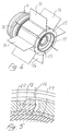
- FIG. 2 shows in greater detail how the rear portion 4 is designed.
- This portion accordingly comprises an inner cavity 8, in which a base-bleed charge 9 is arranged.
- a base-bleed charge 9 is arranged.
- an initiator 10 for the base-bleed charge and a support dome 12 arranged around the outlet 11 thereof.
- Each of the fins 3 is attached to a rotatable spindle 13 aligned essentially in the longitudinal direction of the shell.
- Each such spindle has a bearing point 14 and, respectively, 15 at each end.
- the active areas of the fins which consist of plane plates as in Figs 2-6 in the folded-out position, have been given the general designation 16.
- the active areas 16 of the fins which can be seen more clearly in Fig. 3 , are on the one hand folded down a quarter of a turn around their respective spindles 13 towards the rear body 4 of the shell so that, in the region of their respective spindles 13, they extend essentially tangentially along the rear body 4, and on the other hand curved in at their respective free outer end along this body and moreover covered by a protective cover 17 which is removed as soon as the shell has left the mouth of the barrel.
- the spindles 13 of the fins are, somewhere along their length, in this case at one of their ends, designed with toothed arcs or toothed segments 18 which in turn are all in engagement with an externally toothed control ring 19 characteristic of the invention, which, in a groove 20 adapted thereto inside the rear body 4 close to its outer wall, runs concentrically around the central outlet 21 of the rear body 4 for the base-bleed charge.
- the fins will therefore be covered by the cover 17 which, by interaction between powder gases penetrating into the cover and the vacuum directly outside the mouth of the barrel, is pulled off, whereupon fin fold-out begins immediately.
- the spindles 13 of all the fins 16 via the toothed arcs 18 and then in turn by the externally toothed control ring or synchronizing means, are interconnected to form a continuous system, all the fins will be folded out at the same speed.
Landscapes
- Physics & Mathematics (AREA)
- Fluid Mechanics (AREA)
- Engineering & Computer Science (AREA)
- General Engineering & Computer Science (AREA)
- Toys (AREA)
- Magnetic Bearings And Hydrostatic Bearings (AREA)
- Prostheses (AREA)
- Radar Systems Or Details Thereof (AREA)
- Powder Metallurgy (AREA)
Claims (8)
- Verfahren zur Verwendung beim Abfeuern einer Artilleriegranate (1), die einen hinteren Körper (4) aufweist, der mit einem Gleitführungsband und komplett eingefalteten Leitflächen (3, 16) versehen ist, wobei die Granate (1), so bald wie möglich außerhalb der Mündung des Rohres der Feuerwaffe, durch Ausfalten der Leitflächen (3, 16) in eine Leitflächen-stabilisierte Artilleriegranate umgewandelt wird, wobei jegliche Form von nicht gleichförmiger Leitflächenausfaltung dadurch vermieden wird, dass alle Leitflächen (3, 16), durch daran angepasste Mittel (18, 19, 20), miteinander verbunden sind, um ein System zu bilden, das allen Leitflächen (3, 16) dasselbe Bewegungsmuster und dieselbe Ausfaltungsgeschwindigkeit in jeder Phase des Ausfaltens der Leitflächen (3, 16) verleiht, und dass die Leitflächen (3, 16) durch eine Abdeckung (17) abgedeckt sind, wobei die Abdeckung (17) durch Wechselwirkung zwischen Pulvergasen, welche in die Abdeckung (17) eindringen, und Vakuum direkt außerhalb der Mündung des Rohres abgezogen wird, woraufhin das Ausfalten der Leitflächen (3, 16) unmittelbar beginnt.
- Verfahren gemäß Anspruch 1, dadurch gekennzeichnet, dass das System (18, 19, 20), das die verschiedenen Ausfaltleitflächen verbindet und gleichzeitig steuert, es jeder Leitfläche erlaubt, sich um ihre eigene Drehachse (13) zu bewegen, die im Wesentlichen in der Längsachse der Granate (1) angeordnet ist, von einer ersten, eingefalteten Position, in der ihr aktiver Bereich in dem Bereich der Drehachse (13) im Wesentlichen tangential zu dem hinteren Körper (4) liegt, zu einer zweiten, ausgefalteten Position, in der derselbe aktive Bereich im Wesentlichen radial bezogen auf den hinteren Körper (4) orientiert ist, wobei die Flächen (16) aufgrund der Tatsache, dass alle Flächen (3, 16) durch das Bewegungsübertragungsmittel (18, 19, 20) zum Bilden eines kontinuierlichen Systems verbunden sind, das Ausfalten voneinander entsprechend der Windlast, die auf den aktiven Bereich jeder Fläche einwirkt, fördert oder bremst.
- Verfahren gemäß Anspruch 1 oder 2, dadurch gekennzeichnet, dass das System, das die Wechselwirkung des gleichzeitigen Ausfaltens der verschiedenen Flächen steuert, auf der Verwendung eines gezahnten Rings (19), der die Flächenachsen (13) verbindet, und einer entsprechenden Zahnung (18) jeder Flächenachse basiert.
- Artilleriegranate (1) mit einem Gleitführungsband, die zum Abfeuern aus einem gezogenen Rohr vorgesehen und mit Stabilisierungsflächen (3, 16) versehen ist, die gemäß dem Verfahren gemäß einem der Ansprüche 1 bis 3 nach dem Abfeuern ausgefaltet werden können und die es in ein Geschoss verwandeln, das auf seiner nachfolgenden Flugbahn durch Leitflächen stabilisiert ist, wobei die verschiedenen Leitflächen (3, 16) durch ein Bewegungsübertragungsmittel (18, 19, 20) verbunden sind, das ihre Ausfaltbewegungen zwangsläufig synchronisiert und diese gleichmäßig macht, und wobei die Leitflächen mit einer Abdeckung (17) abgedeckt sind, die, durch Wechselwirkung zwischen Pulvergasen, die in die Abdeckung (17) eintreten, und das Vakuum direkt außerhalb der Mündung des Rohres, abgezogen wird, woraufhin das Ausfalten der Leitflächen unmittelbar beginnt.
- Artilleriegranate (1) gemäß Anspruch 4, dadurch gekennzeichnet, dass alle Flächen (3, 16) ihre eigenen aktiven Bereiche aufweisen und jede Leitfläche (3, 16), die drehbar um eine zugehörige Achse (13) angebracht und im Wesentlichen in der Längsrichtung der Granate (1) und um die Granate (1) herum so angeordnet ist, dass der aktive Bereich von einer ersten, eingefalteten Position, in der der aktive Bereich im Wesentlichen tangential zu dem hinteren Körper (4) der Granate liegt und das freie äußere Ende der Leitflächen (3, 16) in Richtung des hinteren Körpers (4) der Granate gekrümmt sein kann, zu einer zweiten, ausgefalteten Position rotieren kann, in der der aktive Bereich sich im Wesentlichen radial heraus von der Oberfläche des hinteren Körpers (4) der Granate erstreckt, wobei das Bewegungsübertragungsmittel (18, 19, 20), welches das Ausfalten der Fläche steuert, aus mindestens einem Steuerring (19) besteht, der drehbar um die Achse der Granate (1) angeordnet und mit den Achsen (13) aller Leitflächen verbunden ist und deren Bewegung steuert.
- Artilleriegranate (1) gemäß Anspruch 5, dadurch gekennzeichnet, dass der Steuerring (19) eine äußere Zahnung aufweist, während die Achse jeder Fläche (3, 16), an ihrem Verbindungsort mit dem Steuerring (19), eine entsprechende Zahnung (18) in Eingriff mit dem Zahn des Steuerrings (19) aufweist.
- Artilleriegranate (1) gemäß Anspruch 5, dadurch gekennzeichnet, dass der Steuerring (19) eine äußere Rändelung oder eine andere reibungserhöhende Oberflächenbehandlung aufweist, während die Drehachse (13) jeder Fläche (3, 16) eine entsprechende reibungserhöhende Oberflächenbehandlung aufweist, wo die Achsen (13) den Steuerring (19) berühren.
- Artilleriegranate (1) gemäß einem der Ansprüche 4 bis 7, dadurch gekennzeichnet, dass das Bewegungsübertragungsmittel (18, 19, 20), welches das Ausfalten der Flächen (3, 16) steuert, um die Ausstoßöffnung (11) für eine Base-Bleed-Einheit (9) herum angeordnet ist, die in demselben Teil der Granate (1) wie die Flächen (3, 16) angeordnet ist, die wiederum konzentrisch außerhalb der Base-Bleed-Einheit angeordnet sind.
Applications Claiming Priority (3)
| Application Number | Priority Date | Filing Date | Title |
|---|---|---|---|
| SE0100956 | 2001-03-20 | ||
| SE0100956A SE521445C2 (sv) | 2001-03-20 | 2001-03-20 | Sätt att synkronisera fenutfällningen vid en fenstabiliserad artillerigranat samt en i enlighet därmed utformad artillerigranat |
| PCT/SE2002/000550 WO2002079716A1 (en) | 2001-03-20 | 2002-03-20 | Method of synchronizing fin fold-out on a fin-stabilized artillery shell, and an artillery shell designed in accordance therewith |
Publications (2)
| Publication Number | Publication Date |
|---|---|
| EP1370824A1 EP1370824A1 (de) | 2003-12-17 |
| EP1370824B1 true EP1370824B1 (de) | 2017-05-03 |
Family
ID=20283429
Family Applications (1)
| Application Number | Title | Priority Date | Filing Date |
|---|---|---|---|
| EP02713330.5A Expired - Lifetime EP1370824B1 (de) | 2001-03-20 | 2002-03-20 | Verfahren zur synchronisierung des ausklappens der flossen an einem flossenstabilisierten artilleriegeschoss und ein demgemäss konzipiertes artilleriegeschoss |
Country Status (8)
| Country | Link |
|---|---|
| US (2) | US7104497B2 (de) |
| EP (1) | EP1370824B1 (de) |
| CA (1) | CA2441277C (de) |
| IL (3) | IL157972A0 (de) |
| NO (1) | NO327496B1 (de) |
| SE (1) | SE521445C2 (de) |
| WO (1) | WO2002079716A1 (de) |
| ZA (1) | ZA200306817B (de) |
Families Citing this family (23)
| Publication number | Priority date | Publication date | Assignee | Title |
|---|---|---|---|---|
| WO2006088687A1 (en) * | 2005-02-07 | 2006-08-24 | Bae Systems Information And Electronic Systems Integration Inc. | Optically guided munition |
| US7526988B2 (en) * | 2006-05-11 | 2009-05-05 | The Boeing Company | Electromagnetic railgun projectile |
| US7851734B1 (en) | 2007-08-21 | 2010-12-14 | Lockheed Martin Corporation | Acceleration activated fin release mechanism |
| IL190022A (en) * | 2008-03-09 | 2014-01-30 | Israel Aerospace Ind Ltd | A device and method for controlling vehicles and vehicles controlled by them |
| IL207800B (en) * | 2010-08-25 | 2018-12-31 | Bae Systems Rokar Int Ltd | Control apparatus for guiding a cannon shell in flight and method of using same |
| US8584610B1 (en) | 2013-03-07 | 2013-11-19 | Corning Townsend | Spring loaded geared flap rudder |
| RU2535789C1 (ru) * | 2013-08-02 | 2014-12-20 | Открытое акционерное общество "Долгопрудненское научно-производственное предприятие" | Складной аэродинамический руль |
| WO2015179101A2 (en) * | 2014-04-30 | 2015-11-26 | Bae Systems Land & Armaments L.P. | Gun launched munition with strakes |
| US9702673B1 (en) * | 2014-09-24 | 2017-07-11 | The United States Of America As Represented By The Secretary Of The Army | Projectile tail boom with self-locking fin |
| CN104833276B (zh) * | 2015-05-18 | 2016-09-14 | 中国船舶重工集团公司第七○二研究所 | 栅格翼同步展开机构 |
| CN105129082B (zh) * | 2015-09-01 | 2018-07-27 | 湖南云顶智能科技有限公司 | 用于无人机的螺旋桨收折装置 |
| US10184762B2 (en) * | 2015-12-01 | 2019-01-22 | Raytheon Company | Base drag reduction fairing using shape memory materials |
| FR3054030B1 (fr) * | 2016-07-18 | 2018-08-24 | Nexter Munitions | Projectile comprenant un dispositif de deploiement d'une voilure ou ailette |
| US11555679B1 (en) | 2017-07-07 | 2023-01-17 | Northrop Grumman Systems Corporation | Active spin control |
| US12031802B2 (en) | 2017-07-26 | 2024-07-09 | Northrop Grumman Systems Corporation | Despun wing control system for guided projectile maneuvers |
| US11578956B1 (en) | 2017-11-01 | 2023-02-14 | Northrop Grumman Systems Corporation | Detecting body spin on a projectile |
| SE541598C2 (sv) | 2017-11-10 | 2019-11-12 | Bae Systems Bofors Ab | Akterparti för en fenstabiliserad projektil |
| FR3089620B1 (fr) * | 2018-12-11 | 2022-04-01 | Nexter Munitions | Projectile a plans de voilure deployables |
| DE102018133113A1 (de) * | 2018-12-20 | 2020-06-25 | Rheinmetall Air Defence Ag | Lenkflugkörper mit mehreren mittels einer Antriebsanordnung drehbaren Flügeln mit mindestens einem Aktuator und mindestens einem Planetengetriebe |
| RU2704381C1 (ru) * | 2019-02-12 | 2019-10-28 | Акционерное общество "Военно-промышленная корпорация "Научно-производственное объединение машиностроения" | Способ аэродинамического управления летательным аппаратом |
| US11573069B1 (en) | 2020-07-02 | 2023-02-07 | Northrop Grumman Systems Corporation | Axial flux machine for use with projectiles |
| US12313389B1 (en) | 2022-03-11 | 2025-05-27 | Northrop Grumman Systems Corporation | Tunable safe and arming devices and methods of manufacture |
| CN116642382B (zh) * | 2023-04-25 | 2025-12-12 | 北京空间机电研究所 | 一种顺序解锁同步启动的模块化作动装置 |
Family Cites Families (46)
| Publication number | Priority date | Publication date | Assignee | Title |
|---|---|---|---|---|
| US2928346A (en) * | 1951-09-06 | 1960-03-15 | David D Grimes | Arming mechanism |
| NL186136B (nl) | 1953-04-23 | Kendall & Co | Niet-geweven textielmateriaal, dat geschikt is voor gebruik als een medisch verband. | |
| US2822995A (en) * | 1954-01-27 | 1958-02-11 | Bowen Max | Adjustable wing aircraft |
| US3260205A (en) * | 1964-09-28 | 1966-07-12 | Aerojet General Co | Fin actuated spin vane control device and method |
| US3415520A (en) * | 1966-09-26 | 1968-12-10 | Navy Usa | Maneuvering tow target |
| US3498178A (en) * | 1968-02-23 | 1970-03-03 | Emerson Electric Co | Cylindrical ammunition magazine for storing and discharging linked ammunition |
| DE1728305A1 (de) | 1968-09-25 | 1972-04-20 | Feistel Pyrotech Fab | Geschossleitwerk |
| SE339646B (de) | 1970-01-08 | 1971-10-11 | Bofors Ab | |
| FR2356118A1 (fr) | 1976-06-25 | 1978-01-20 | Europ Propulsion | Empennage pour projectile |
| US4272040A (en) * | 1978-07-14 | 1981-06-09 | General Dynamics, Pomona Division | Aerodynamic control mechanism for thrust vector control |
| US4296895A (en) | 1979-01-15 | 1981-10-27 | General Dynamics Corporation | Fin erection mechanism |
| SE432670B (sv) * | 1979-09-27 | 1984-04-09 | Kurt Andersson | Sett att stabilisera en artilleriprojektil och i slutfasen korrigera dess bana och artilleriprojektil for genomforande av settet |
| US4323208A (en) * | 1980-02-01 | 1982-04-06 | British Aerospace | Folding fins |
| SE433261B (sv) * | 1980-03-31 | 1984-05-14 | Andersson Kurt Goeran | En inledningsvis rotationsstabiliserad ballistisk artilleriprojektil forsedd med utfellbara fenor |
| US4683830A (en) * | 1981-05-29 | 1987-08-04 | Hydroconic Limited | Ship's steering systems |
| US4554989A (en) * | 1983-01-20 | 1985-11-26 | Peter Gruich | Multimotor modular electric drive powertrain system for turbine powered vehicles |
| IT8320887U1 (it) | 1983-02-22 | 1984-08-22 | Simmel Spa | Freno aerodinamico per corpi rotanti, in particolare proiettili |
| US4575025A (en) * | 1984-04-25 | 1986-03-11 | Sadvary John W | Fin deployment mechanism for missiles |
| US4624424A (en) * | 1984-11-07 | 1986-11-25 | The Boeing Company | On-board flight control drag actuator system |
| US4699333A (en) * | 1984-11-07 | 1987-10-13 | The Boeing Company | On-board flight control panel system |
| US4690350A (en) * | 1985-12-19 | 1987-09-01 | Raytheon Company | Despinning mechanism |
| FR2634548B1 (de) * | 1988-07-22 | 1993-09-03 | Thomson Brandt Armements | |
| FR2657703B1 (fr) * | 1990-01-26 | 1992-04-10 | Thomson Brandt Armements | Dispositif pour la commande d'attitude en roulis d'un projectile stabilise par empennage. |
| FR2659433B1 (fr) * | 1990-03-09 | 1992-05-15 | Thomson Brandt Armements | Perfectionnements a des empennages a ailettes deployables. |
| US5505408A (en) * | 1993-10-19 | 1996-04-09 | Versatron Corporation | Differential yoke-aerofin thrust vector control system |
| US5829715A (en) * | 1996-04-19 | 1998-11-03 | Lockheed Martin Vought Systems Corp. | Multi-axis unfolding mechanism with rate controlled synchronized movement |
| US5662290A (en) * | 1996-07-15 | 1997-09-02 | Versatron Corporation | Mechanism for thrust vector control using multiple nozzles |
| DE19635847C2 (de) * | 1996-09-04 | 1998-07-16 | Daimler Benz Aerospace Ag | Lenkflugkörper mit Staustrahlantrieb |
| DE19640540C1 (de) * | 1996-10-01 | 1998-04-02 | Daimler Benz Aerospace Ag | Ruderstellsystem für einen Lenkflugkörper |
| SE508858C2 (sv) | 1997-03-25 | 1998-11-09 | Bofors Ab | Fenstabiliserad granat |
| US5950963A (en) * | 1997-10-09 | 1999-09-14 | Versatron Corporation | Fin lock mechanism |
| US6247666B1 (en) * | 1998-07-06 | 2001-06-19 | Lockheed Martin Corporation | Method and apparatus for non-propulsive fin control in an air or sea vehicle using planar actuation |
| SE518665C2 (sv) * | 2000-03-21 | 2002-11-05 | Bofors Weapon Sys Ab | Fenstabiliserad artillerigranat |
| DE10015514B4 (de) * | 2000-03-30 | 2007-10-04 | Rheinmetall Waffe Munition Gmbh | Flügelstabilisiertes Geschoß |
| US6360987B1 (en) * | 2000-05-23 | 2002-03-26 | Bae Systems Integrated Defense Solutions | Methods and apparatus for swash plate guidance and control |
| SE518657C2 (sv) * | 2000-07-03 | 2002-11-05 | Bofors Defence Ab | Fenstabiliserad styrbar projektil |
| SE519757C2 (sv) * | 2000-08-15 | 2003-04-08 | Bofors Defence Ab | Styrbar artilleriprojektil med extremt lång skottvidd |
| US7086337B2 (en) * | 2000-09-28 | 2006-08-08 | Klein John M | Non-lethal projectile ammunition |
| US6474594B1 (en) * | 2001-05-11 | 2002-11-05 | Raytheon Company | Output shaft assembly for a missile control actuation unit |
| TW583264B (en) * | 2001-09-26 | 2004-04-11 | Nanya Plastics Corp | Improved copolyester with improved extrusion processing and color for extrusion blow molding |
| US6571715B1 (en) * | 2002-03-11 | 2003-06-03 | Raytheon Company | Boot mechanism for complex projectile base survival |
| US6761331B2 (en) * | 2002-03-19 | 2004-07-13 | Raytheon Company | Missile having deployment mechanism for stowable fins |
| US6637699B2 (en) * | 2002-03-25 | 2003-10-28 | Lockheed Martin Corporation | Method and apparatus for controlling a trajectory of a projectile |
| ES2238107B1 (es) * | 2002-06-13 | 2006-11-01 | Iñigo Echenique Gordillo | Sistema de estabilizadores integrados para buques. |
| US6869043B1 (en) * | 2003-03-24 | 2005-03-22 | At&T Corp. | Deployable flare with simplified design |
| US6921052B2 (en) * | 2003-11-28 | 2005-07-26 | The United States Of America As Represented By The Secretary Of The Army | Dragless flight control system for flying objects |
-
2001
- 2001-03-20 SE SE0100956A patent/SE521445C2/sv not_active IP Right Cessation
-
2002
- 2002-03-20 WO PCT/SE2002/000550 patent/WO2002079716A1/en not_active Ceased
- 2002-03-20 IL IL15797202A patent/IL157972A0/xx unknown
- 2002-03-20 EP EP02713330.5A patent/EP1370824B1/de not_active Expired - Lifetime
- 2002-03-20 CA CA002441277A patent/CA2441277C/en not_active Expired - Lifetime
- 2002-03-20 US US10/471,458 patent/US7104497B2/en not_active Expired - Lifetime
-
2003
- 2003-09-01 ZA ZA200306817A patent/ZA200306817B/en unknown
- 2003-09-17 IL IL157972A patent/IL157972A/en unknown
- 2003-09-19 NO NO20034174A patent/NO327496B1/no not_active IP Right Cessation
-
2006
- 2006-09-11 US US11/530,520 patent/US7487934B2/en not_active Expired - Lifetime
-
2007
- 2007-02-01 IL IL181105A patent/IL181105A/en unknown
Also Published As
| Publication number | Publication date |
|---|---|
| US20070114323A1 (en) | 2007-05-24 |
| IL181105A (en) | 2009-07-20 |
| IL157972A0 (en) | 2004-03-28 |
| NO327496B1 (no) | 2009-07-20 |
| WO2002079716A1 (en) | 2002-10-10 |
| ZA200306817B (en) | 2004-09-01 |
| IL181105A0 (en) | 2007-07-04 |
| EP1370824A1 (de) | 2003-12-17 |
| US7487934B2 (en) | 2009-02-10 |
| IL157972A (en) | 2009-07-20 |
| US20050229806A1 (en) | 2005-10-20 |
| SE521445C2 (sv) | 2003-11-04 |
| CA2441277A1 (en) | 2002-10-10 |
| NO20034174L (no) | 2003-11-10 |
| CA2441277C (en) | 2009-06-09 |
| SE0100956D0 (sv) | 2001-03-20 |
| US7104497B2 (en) | 2006-09-12 |
| SE0100956L (sv) | 2002-09-21 |
| NO20034174D0 (no) | 2003-09-19 |
Similar Documents
| Publication | Publication Date | Title |
|---|---|---|
| EP1370824B1 (de) | Verfahren zur synchronisierung des ausklappens der flossen an einem flossenstabilisierten artilleriegeschoss und ein demgemäss konzipiertes artilleriegeschoss | |
| US10788297B2 (en) | Artillery projectile with a piloted phase | |
| EP1297292B1 (de) | Verfahren und vorrichtung für artilleriegeschosse | |
| EP1297293B1 (de) | Flügelstabilisiertes geschoss | |
| EP0970346A1 (de) | Verfahren und vorrichtung für ein flügelstabilisiertes geschoss, das eine bodensogreduzierung hat | |
| US6336609B1 (en) | Method and device for a fin-stabilized base-bleed shell | |
| RU2032139C1 (ru) | Управляемый снаряд с поворотной боевой частью (варианты) | |
| EP1185836B1 (de) | Verriegelungs- und verschiebevorrichtung in einer rakete | |
| EP0038310B1 (de) | Ballistisches Geschoss mit ausspreizbarem Flossenleitwerk | |
| AU771164B2 (en) | Device for exerting drag | |
| US5679919A (en) | Method and apparatus for imparting to an airborne warhead a desired pattern of movement | |
| RU2165584C1 (ru) | Реактивный снаряд |
Legal Events
| Date | Code | Title | Description |
|---|---|---|---|
| PUAI | Public reference made under article 153(3) epc to a published international application that has entered the european phase |
Free format text: ORIGINAL CODE: 0009012 |
|
| 17P | Request for examination filed |
Effective date: 20031008 |
|
| AK | Designated contracting states |
Kind code of ref document: A1 Designated state(s): AT BE CH CY DE DK ES FI FR GB GR IE IT LI LU MC NL PT SE TR |
|
| AX | Request for extension of the european patent |
Extension state: AL LT LV MK RO SI |
|
| 17Q | First examination report despatched |
Effective date: 20100308 |
|
| RAP1 | Party data changed (applicant data changed or rights of an application transferred) |
Owner name: BAE SYSTEMS BOFORS AB |
|
| GRAP | Despatch of communication of intention to grant a patent |
Free format text: ORIGINAL CODE: EPIDOSNIGR1 |
|
| INTG | Intention to grant announced |
Effective date: 20160916 |
|
| GRAS | Grant fee paid |
Free format text: ORIGINAL CODE: EPIDOSNIGR3 |
|
| GRAA | (expected) grant |
Free format text: ORIGINAL CODE: 0009210 |
|
| AK | Designated contracting states |
Kind code of ref document: B1 Designated state(s): DE ES FR GB IT SE |
|
| REG | Reference to a national code |
Ref country code: GB Ref legal event code: FG4D |
|
| REG | Reference to a national code |
Ref country code: DE Ref legal event code: R096 Ref document number: 60248853 Country of ref document: DE |
|
| PG25 | Lapsed in a contracting state [announced via postgrant information from national office to epo] |
Ref country code: ES Free format text: LAPSE BECAUSE OF FAILURE TO SUBMIT A TRANSLATION OF THE DESCRIPTION OR TO PAY THE FEE WITHIN THE PRESCRIBED TIME-LIMIT Effective date: 20170503 |
|
| PG25 | Lapsed in a contracting state [announced via postgrant information from national office to epo] |
Ref country code: SE Free format text: LAPSE BECAUSE OF FAILURE TO SUBMIT A TRANSLATION OF THE DESCRIPTION OR TO PAY THE FEE WITHIN THE PRESCRIBED TIME-LIMIT Effective date: 20170503 |
|
| REG | Reference to a national code |
Ref country code: DE Ref legal event code: R097 Ref document number: 60248853 Country of ref document: DE |
|
| PLBE | No opposition filed within time limit |
Free format text: ORIGINAL CODE: 0009261 |
|
| STAA | Information on the status of an ep patent application or granted ep patent |
Free format text: STATUS: NO OPPOSITION FILED WITHIN TIME LIMIT |
|
| REG | Reference to a national code |
Ref country code: FR Ref legal event code: PLFP Year of fee payment: 17 |
|
| 26N | No opposition filed |
Effective date: 20180206 |
|
| PGFP | Annual fee paid to national office [announced via postgrant information from national office to epo] |
Ref country code: IT Payment date: 20200323 Year of fee payment: 19 Ref country code: GB Payment date: 20200327 Year of fee payment: 19 Ref country code: DE Payment date: 20200327 Year of fee payment: 19 |
|
| PGFP | Annual fee paid to national office [announced via postgrant information from national office to epo] |
Ref country code: FR Payment date: 20210325 Year of fee payment: 20 |
|
| REG | Reference to a national code |
Ref country code: DE Ref legal event code: R119 Ref document number: 60248853 Country of ref document: DE |
|
| GBPC | Gb: european patent ceased through non-payment of renewal fee |
Effective date: 20210320 |
|
| PG25 | Lapsed in a contracting state [announced via postgrant information from national office to epo] |
Ref country code: GB Free format text: LAPSE BECAUSE OF NON-PAYMENT OF DUE FEES Effective date: 20210320 Ref country code: DE Free format text: LAPSE BECAUSE OF NON-PAYMENT OF DUE FEES Effective date: 20211001 |
|
| PG25 | Lapsed in a contracting state [announced via postgrant information from national office to epo] |
Ref country code: IT Free format text: LAPSE BECAUSE OF NON-PAYMENT OF DUE FEES Effective date: 20210320 |