EP1370837B1 - Dosiervorrichtung für schüttgüter - Google Patents
Dosiervorrichtung für schüttgüter Download PDFInfo
- Publication number
- EP1370837B1 EP1370837B1 EP02726185A EP02726185A EP1370837B1 EP 1370837 B1 EP1370837 B1 EP 1370837B1 EP 02726185 A EP02726185 A EP 02726185A EP 02726185 A EP02726185 A EP 02726185A EP 1370837 B1 EP1370837 B1 EP 1370837B1
- Authority
- EP
- European Patent Office
- Prior art keywords
- dosing device
- crank
- trough
- dosing
- drive motor
- Prior art date
- Legal status (The legal status is an assumption and is not a legal conclusion. Google has not performed a legal analysis and makes no representation as to the accuracy of the status listed.)
- Expired - Lifetime
Links
Images





Classifications
-
- B—PERFORMING OPERATIONS; TRANSPORTING
- B65—CONVEYING; PACKING; STORING; HANDLING THIN OR FILAMENTARY MATERIAL
- B65G—TRANSPORT OR STORAGE DEVICES, e.g. CONVEYORS FOR LOADING OR TIPPING, SHOP CONVEYOR SYSTEMS OR PNEUMATIC TUBE CONVEYORS
- B65G65/00—Loading or unloading
- B65G65/30—Methods or devices for filling or emptying bunkers, hoppers, tanks, or like containers, of interest apart from their use in particular chemical or physical processes or their application in particular machines, e.g. not covered by a single other subclass
- B65G65/34—Emptying devices
- B65G65/40—Devices for emptying otherwise than from the top
- B65G65/46—Devices for emptying otherwise than from the top using screw conveyors
-
- B—PERFORMING OPERATIONS; TRANSPORTING
- B65—CONVEYING; PACKING; STORING; HANDLING THIN OR FILAMENTARY MATERIAL
- B65D—CONTAINERS FOR STORAGE OR TRANSPORT OF ARTICLES OR MATERIALS, e.g. BAGS, BARRELS, BOTTLES, BOXES, CANS, CARTONS, CRATES, DRUMS, JARS, TANKS, HOPPERS, FORWARDING CONTAINERS; ACCESSORIES, CLOSURES, OR FITTINGS THEREFOR; PACKAGING ELEMENTS; PACKAGES
- B65D88/00—Large containers
- B65D88/26—Hoppers, i.e. containers having funnel-shaped discharge sections
- B65D88/32—Hoppers, i.e. containers having funnel-shaped discharge sections in multiple arrangement
-
- B—PERFORMING OPERATIONS; TRANSPORTING
- B65—CONVEYING; PACKING; STORING; HANDLING THIN OR FILAMENTARY MATERIAL
- B65D—CONTAINERS FOR STORAGE OR TRANSPORT OF ARTICLES OR MATERIALS, e.g. BAGS, BARRELS, BOTTLES, BOXES, CANS, CARTONS, CRATES, DRUMS, JARS, TANKS, HOPPERS, FORWARDING CONTAINERS; ACCESSORIES, CLOSURES, OR FITTINGS THEREFOR; PACKAGING ELEMENTS; PACKAGES
- B65D88/00—Large containers
- B65D88/54—Large containers characterised by means facilitating filling or emptying
- B65D88/64—Large containers characterised by means facilitating filling or emptying preventing bridge formation
- B65D88/66—Large containers characterised by means facilitating filling or emptying preventing bridge formation using vibrating or knocking devices
-
- B—PERFORMING OPERATIONS; TRANSPORTING
- B65—CONVEYING; PACKING; STORING; HANDLING THIN OR FILAMENTARY MATERIAL
- B65G—TRANSPORT OR STORAGE DEVICES, e.g. CONVEYORS FOR LOADING OR TIPPING, SHOP CONVEYOR SYSTEMS OR PNEUMATIC TUBE CONVEYORS
- B65G33/00—Screw or rotary spiral conveyors
- B65G33/08—Screw or rotary spiral conveyors for fluent solid materials
-
- G—PHYSICS
- G01—MEASURING; TESTING
- G01G—WEIGHING
- G01G13/00—Weighing apparatus with automatic feed or discharge for weighing-out batches of material
- G01G13/02—Means for automatically loading weigh pans or other receptacles, e.g. disposable containers, under control of the weighing mechanism
- G01G13/022—Material feeding devices
- G01G13/026—Material feeding devices by mechanical conveying means, e.g. belt or vibratory conveyor
Definitions
- the present invention relates to a metering device for bulk goods, comprising a holding frame in which a Trough with a dosing screw is arranged, also one Drive motor and at least a first vibrating paddle, the trough being at least two opposite one another Has side walls, at least one of these side walls is flexible and the vibrating paddle on this flexible Sidewall is arranged.
- the metering device is preferably designed as follows:
- the entire trough is made of a flexible material and can be hung in the holding frame.
- the drive motor is arranged in the rear area of the holding frame.
- the vibrating paddles are attached to the side of the one Trough arranged in the holding frame.
- Dosing devices of this type are known and are found in various industrial uses, for example in chemical, pharmaceutical, food technology Companies, etc.
- the bulk material e.g. Powder, granules, Pellets, flakes, chips, flakes, fibers and the like to keep flowable and a baking on the Preventing trough walls are at least on the side walls of the square trough facilities in the top view for periodically arching predetermined wall areas provided inside by an activation of the bulk material the natural flow behavior of the bulk material support to compacting, bridging as well as to prevent caking.
- the invention is therefore based on the object dosing device mentioned another significant Improve the mass flow with a particular effective prevention of vaulting in the trough reach, already formed bulk bridges be broken quickly and effectively. Even extremely poorly flowable and strong for caking as well Bulk materials that tend to stick to the walls of the trough can be dosed easily.
- This task is performed with the dosing device mentioned at the beginning solved according to the invention in that the upper edges the side walls mentioned are not parallel to each other are aligned and that the top chewing of the non-parallel side walls towards each other in the direction of the outlet of the dosing screw to run.
- This type of trough results in the direction from the front at the screw outlet different angles of inclination to the rear Side walls with the non-parallel top edges.
- this trough geometry can be a bulk material bridge or do not form a vault at all or only unstably.
- a possibly with poorly flowing bulk goods nevertheless formed bulk material bridge is caused by the movement the paddle acting on the flexible side walls destabilized and destroyed more effectively and quickly because the side walls that support the bulk bridge form, unlike troughs with a rectangular geometry (see also FIGS. 8 and 10) not parallel to one another run.
- the top edges of the non-parallel Sidewalls towards the outlet of the Dosing screw to run on each other. Because that flexible, periodically arching sidewalls due to their inclination, the bulk material Throw it to the wide end of the trough at the back Bulk material targeted to that part of the floor area of the Troges at which the snail gear fills.
- the bulk goods are discharged at the narrow end of the Trough on which the outlet is arranged.
- the trough has a top view from above Trapezoidal shape, with the dosing screw essentially. at right angles to the parallel sides of the trapezoid is arranged. Doing so under a trapeze is more common Wise a flat square with two parallel ones, but not understood equally long pages.
- each of the above mentioned opposite side walls at least one Vibrating paddle is arranged and both side walls are flexible are.
- the bulk material is thus from both sides of the Dosing device moved mechanically.
- the drive motor between an operating position coupled with the dosing screw and a decoupled decommissioning position is that the vibrating paddle or paddles with a Vibration shaft can be driven via a vibration drive or are that means, especially gear means, for a Vibratory drive connection between the drive motor of the Dosing screw and the vibrating shaft of the vibrating paddle or the vibrating paddle are provided.
- the vibratory drive preferably essentially drives one arranged parallel to a side wall of the trough Vibrating shaft with the vibrating paddle.
- the Dosing screw drive motor complete assembly pivoted so that the dosing screw with storage to the rear, i.e. against the conveying direction, can be pulled out.
- gear means assigned to the pivotable drive motor are and include connecting means which the Drive connection from the gear means to the oscillating shaft of the paddle even when swiveling the drive motor in the decommissioning position without dismantling any Parts maintained, as with an exemplary embodiment is explained in more detail.
- the gear means can also the holding frame according to another embodiment be assigned and for example when pivoting the drive motor in its operating position, similar like the dosing screw, can be coupled with it, or but with a gear element in the drive train of the dosing screw are constantly in drive connection, as on the basis another embodiment is shown.
- crank mechanism that has a crank rod with connected to a crank arm arranged on the oscillating shaft is.
- crank mechanisms are structurally very simple components and find in the implementation of rotary movements multiple use in vibratory movements.
- the eccentricity of the drive motor side and / or the pivot point on the oscillating shaft is variable.
- the amplitude of the swinging motion the larger the paddle, the greater the eccentricity of the respective articulation point.
- crank mechanism on the drive motor side is a rotary drive Crank disc with one or more eccentric articulation points arranged to the axis of rotation of the crank disk for the crank rod.
- crank disk is an output gear one is driven by the drive motor gear train.
- Gear wheels allow different in a simple way Under or translation ratios between the rotational frequency of the drive motor of the dosing screw and the frequency of the paddle.
- crank pulley is a toothed belt pulley, which has a toothed belt with one on the output shaft the drive motor arranged as a toothed belt pulley trained drive gear is drive-connected.
- Such toothed belt gears have the advantage that they are largely maintenance-free and run very quietly.
- the drive side crank mechanism is on a drive motor supporting the pivot axis pivotally mounted on the support bracket and that the crank rod with the oscillating shaft side Crank arm is connected via a hinge joint, the Hinge axis at a given swing position of the crank arm with the pivot axis of the carrier at least almost aligned.
- the hinge allows at the predetermined swing position of the crank arm Pivoting movement of the crank rod around the hinge axis, if the carrier is arranged around the one aligned with the hinge axis Swivel axis is pivoted.
- crank rod with the hinge joint with another connecting swivel joint one to the hinge axis and to the longitudinal axis of the crank rod joint axis connected at right angles.
- Dosing devices of the type mentioned have in general paddles arranged on both sides of the trough; in such a case the invention further provides that at least one more paddle on the first paddle facing away from a trough in the holding frame is arranged and that an oscillating shaft further Paddle with the oscillation wave of the first paddle over a gear mechanism is coupled.
- This gear mechanism preferably comprises each a crank arm arranged on each oscillating shaft, the are connected to each other via a crank rod.
- the means for a vibratory drive connection between the drive motor and the Vibration shaft are designed as a gear mechanism, which arranged one on each vibration shaft Crank arm includes, and that the crank arms via a crank rod are interconnected.
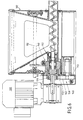
- the dosing device shown in Figures 1 to 5 comprises an approximately housing-like holding frame 2, in the upper opening a trough 4 can be hung in such a way that the upper peripheral edges 6 of the trough 4 the upper Grip over circumferential edges 8 of the housing-like holding frame 2.
- the housing-like holding frame 2 has a rear wall 10 and a front wall 12 that is vertical and parallel to each other stand, as well as two side walls 14, 16, which are also vertically, but converging in the direction of arrow 18 run so that the holding frame 2 in a plan view is trapezoidal with a central plane of symmetry 19.
- Such a shape is preferably chosen if several dosing devices in a circle around a central one Delivery point should be arranged around.
- the trough 4 is approximately wedge-shaped. He has one Rear wall 20 and a front wall 22, each different Have inclination angles to the vertical, as well two side walls 24 (see also Figures 4 and 5), the illustrated embodiment to a vertical Longitudinal median plane of the trough 4, that with the plane of symmetry 19 of the support frame 2 coincides, arranged symmetrically are and converge down so that they are a Form floor channel 26.
- the side walls 24 also run in line with the trapezoidal shape of the support frame from the rear wall 20 converging towards the front wall 22.
- a metering screw 28 arranged by a in rear area of the support frame 2 arranged Drive motor 30 via a coupling with the dosing screw 28 Drive shaft 32 can be driven, and the bulk material located in trough 4 via an outlet connection 34 transported to the outside.
- the outlet connection 34 in one front bearing approach 36 of the trough 4 added; a rear Bearing approach 38 of the trough 4 serves to accommodate the front section of a bearing and clutch assembly 40 with a connecting shaft 42 and its storage.
- the connecting shaft 42 provides a drive connection between the drive shaft 32 of the drive motor 30 and the dosing screw 28, as can be seen in FIGS to 3 results easily.
- the drive motor 30 is fastened to a carrier 44, which on the rear wall 10 of the support frame 2 by means of a hinge 46 about a vertical hinge axis 78 from the operating position shown in Figure 2 in the pivoted out of operation position shown in Figure 3 can be.
- the trough 4 from the holding frame 2 can be removed, the carrier 44 with the drive motor 30 arranged thereon in the in FIG shown inoperative position are pivoted, the drive shaft 32 being uncoupled from the connecting shaft , whereupon the bearing and clutch assembly 40 together with the dosing screw 28 coupled with it can be pulled out to the rear; furthermore the attached to the front wall 12 by means of a flange 35 Outlet port 34 are loosened and pulled off to the front. So that the trough 4 is released and can move upwards the support frame 2 are lifted out. Insertion a trough 4 in the holding frame 2 is carried out analogously in vice versa.
- the trough 4 consists of a soft plastic material, preferably made of a PU material so that its walls easily deformable, i.e. can be arched inwards. How the figures show, are in the holding frame 2 laterally next to the trough 4 so-called vibrating paddles 48, 50 are provided, each on assigned vibration waves 52 or 54 are arranged.
- the paddles 48, 50 perform torsional vibratory movements from the side walls 24 hit the trough 4 and the bulk material in the trough loosen.
- the oscillating shafts 52, 54 are each assigned, not specified bearings on the rear wall 10 and the front wall 12 of the support frame 2 attached.
- the vibration wave 52 is behind the rear wall 10 of the holding device 2 extended outside; at the extension 52 'is a crank arm 56 arranged over which a torsional swing movement in the oscillating shaft 52 can be initiated.
- the vibration drive of the vibration shaft 52 is special Gear means from the drive motor 30 of the metering screw 28 derived.
- These gear means include one with the Drive motor 30 drive-connected crank mechanism 58, which is connected to crank arm 56 via a crank rod 60 is.
- the crank mechanism 58 is essentially from a rotationally driven crank disk 62 with an eccentric to its pivot axis 64 arranged pivot point 66 for the crank rod 60.
- the crank disc 62 is over a crank disk shaft 68 is mounted on the carrier 44, on the also the drive motor 30 is attached.
- the crank disc 62 forms an output gear one of the drive motor driven gear train; on the drive shaft 32 of the Drive motor 30, a drive gear 70 is keyed.
- the drive gear 70 and the crank disk 62 are each designed as toothed belt pulleys, the are connected via a toothed belt 72.
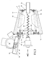
- crank mechanism 58 firmly arranged on the carrier 44 and is when pivoting the drive motor 30 in its inoperative position with panned. So that the drive connection from the crank mechanism 58 to the crank arm 56 of the Vibration shaft 52 also obtained with this pivoting movement can remain, the crank rod 60 with the crank arm 56th connected via a hinge joint 74, the hinge axis 76 at a predetermined, shown in Figure 4 Swinging position of the crank arm 56 at least approximately aligned with the pivot axis 78 of the carrier 44.
- the crank rod 60 is connected to the hinge axis 76 rotatable part of the hinge joint 74 via another Connecting swivel joint 80 connected to the crank movement the crank rod 60 due to the rotation of the crank disk 62 enables.
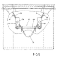
- This gear mechanism 82 includes a crank arm 84 arranged on the oscillating shaft 52, a crank arm 86 and arranged on the oscillating shaft 54 a crank rod 88 connecting the crank arms 84, 86.
- the drive gear 70 and / or the crank disc 62 are exchanged in such a way that they differ Gear ratios between the rotational frequency the drive shaft 32 and thus the metering screw 28 on the one hand and the oscillation frequency of the oscillation waves 52, 54 on the other hand. It has been shown that at poorly flowing bulk goods a ratio of 1: 1 is advantageous; with very good flowing bulk goods the speed of the dosing screw three times as high as that Vibration frequency of the paddles. With a default setting, at which the rotational frequency of the dosing screw twice the vibration frequency of the paddle, a wide range of many bulk goods is optimally covered.
- FIG. 6 shows a metering device in one of FIG. 1 corresponding view.
- the dosing device of FIG. 6 differs from the metering device of FIG. 1 only in the arrangement and design of the crank mechanism, so it’s enough to describe only this one.
- the Crank mechanism 158 in turn includes a toothed belt pulley trained crank disc 162 and also a Drive gear wheel designed as a toothed belt pulley 170.
- the Crank disk 162 on a lower portion of the rear wall 110 of the support frame 102 stored.
- the drive gear wheel 170 is formed by a coupling sleeve 190, the Is part of the bearing and clutch assembly 140 and is rotatably connected to the connecting shaft 142.
- the Crank disk 162 and the drive gear 170 are again connected to one another by means of a toothed belt 172. Since the crank mechanism 158 with the support frame 102 connected, it remains when the Drive motor 130 in its inoperative position on his Place. Therefore, a hinge joint can be used accordingly the hinge joint 74 is eliminated, so that the crank arm 160 only via a connecting swivel joint 80 corresponding connection swivel joint with the not shown Crank arm of the oscillating shaft 152 is connected.
- FIGS of the trough The advantages of the trapezoidal shape are shown in FIGS of the trough.
- the working area of the dosing screw 28 is in Figures 9 and 10 with the reference numeral Designated 206. Due to the trapezoidal design of the trough 4 ( Figures 7 and 9) result in the direction different from the front at the screw outlet to the rear Angle of inclination of the side walls 14, 16, how special is apparent from Figure 9. Through this trough geometry a possibly formed with poorly flowing powder Product bridge 204 by the movement of the paddles 48, 50 destroyed more effectively because the trough walls 14, 16, form the supports for the product bridge 204, other than for troughs with rectangular geometry ( Figures 8 and 10) not parallel to each other.
Landscapes
- Engineering & Computer Science (AREA)
- Mechanical Engineering (AREA)
- Physics & Mathematics (AREA)
- General Physics & Mathematics (AREA)
- Basic Packing Technique (AREA)
- Filling Or Emptying Of Bunkers, Hoppers, And Tanks (AREA)
- Weight Measurement For Supplying Or Discharging Of Specified Amounts Of Material (AREA)
- Feeding Of Articles To Conveyors (AREA)
- Catching Or Destruction (AREA)
- Auxiliary Methods And Devices For Loading And Unloading (AREA)
Description
- Figur 1
- schematisch eine Dosiervorrichtung in einer Seitenansicht;
- Figur 2
- eine Dosiervorrichtung (gezeichnet ohne den Trog 4) gemäß der Figur 1 in einer Draufsicht, wobei der Antriebsmotor eine Betriebsstellung einnimmt;
- Figur 3
- in einer verkleinerten Darstellung eine Draufsicht (gezeichnet ohne den Trog 4) etwa gemäß der Figur 2, wobei der Antriebsmotor in eine Außerbetriebsstellung verschwenkt ist;
- Figur 4
- schematisch Einzelheiten der Getriebemittel für den Schwingantrieb der Paddel in einer Ansicht zur Rückwand des Haltegestells hin;
- Figur 5
- Einzelheiten des Schwingantriebes für ein zweites Paddel in einer Ansicht entgegen der Richtung des Pfeiles 18 in Figur 2;
- Figur 6
- in einer Seitenansicht etwa entsprechend der Figur 1 eine andere Ausgestaltung der Dosiervorrichtung;
- Figur 7
- eine Draufsicht auf einen erfindungsgemäßen trapezförmigen Trog;
- Figur 8
- eine Draufsicht auf einen rechteckigen Trog nach dem Stand der Technik;
- Figur 9
- eine Ansicht entsprechend dem Pfeil 200 in Figur 7 in das Innere des Troges;
- Figur 10
- eine Ansicht in Richtung des Pfeils 202 in Figur 8, ebenfalls in das Innere des Troges.
- 2
- Haltegestell
- 4
- Trog
- 6
- obere Umfangsränder von 4
- 8
- obere Umfangsränder von 2
- 10
- Rückwand
- 12
- Vorderwand
- 14, 14'
- Seitenwand
- 16, 16'
- Seitenwand
- 18
- Pfeil
- 19
- Symmetrieebene
- 20
- Rückwand
- 22
- Vorderwand
- 24
- Seitenwand
- 26
- Bodenrinne
- 28
- Dosierschnecke
- 30
- Antriebsmotor
- 32
- Antriebswelle
- 34
- Auslassstutzen
- 35
- Flansch
- 36
- Lageransatz
- 38
- Lageransatz
- 40
- Lagerungs- und Kupplungsanordnung
- 42
- Verbindungswelle
- 44
- Träger
- 46
- Scharnier
- 48
- erstes Rüttel-Paddel
- 50
- Rüttel-Paddel
- 52
- Schwingwelle
- 54
- Schwingwelle
- 56
- Kurbelarm
- 58
- Kurbelmechanismus
- 60
- Kurbelstange
- 62
- Kurbelscheibe
- 64
- Drehachse
- 66
- Anlenkpunkt
- 68
- Kurbelscheibenwelle
- 70
- Antriebsgetrieberad
- 72
- Zahnriemen
- 74
- Scharniergelenk
- 76
- Scharnierachse
- 78
- Schwenkachse
- 80
- Verbindungsschwenkgelenk
- 82
- Getriebemechanismus
- 84
- Kurbelarm
- 86
- Kurbelarm
- 88
- Kurbelstange
- 102
- Haltegestell
- 110
- Rückwand
- 130
- Antriebsmotor
- 140
- Lagerungs- und Kupplungsanordnung
- 142
- Verbindungswelle
- 152
- Schwingwelle
- 158
- Kurbelmechanismus
- 160
- Kurbelstange
- 162
- Kurbelscheibe
- 170
- Antriebsgetrieberad
- 172
- Zahnriemen
- 190
- Kupplungsbuchse
- 200
- Pfeil
- 202
- Pfeil
- 204
- Produktbrücke
- 206
- Arbeitsraum der Dosierschnecke
Claims (17)
- Dosiervorrichtung für Schüttgüter, umfassend ein Haltegestell (2), in dem ein Trog (4) mit einer Dosierschnecke (28) angeordnet ist, ferner einen Antriebsmotor (30) und wenigstens ein erstes Rüttel-Paddel (48), wobei der Trog (4) mindestens zwei sich gegenüber liegende Seitenwände (14, 16) aufweist, mindestens eine dieser Seitenwände (14) flexibel ist und das Rüttel-Paddel (48) an dieser flexiblen Seitenwand (14) angeordnet ist,
dadurch gekennzeichnet, dass die Oberkanten der genannten Seitenwände (14, 16) nichtparallel zueinander ausgerichtet sind und
dass die Oberkanten der nichtparallelen Seitenwände (14, 16) in Richtung des Auslasses der Dosierschnecke (28) aufeinander zu laufen. - Dosiervorrichtung nach Anspruch 1,
dadurch gekennzeichnet, dass die Seitenwände (14, 16) des Troges (4) mit den nichtparallelen Oberkanten zum Bodenbereich hin keilförmig aufeinander zu laufen und dass die Dosierschnecke (28) in diesem Bodenbereich des Troges (4) angeordnet ist. - Dosiervorrichtung nach einem der vorherigen Ansprüche,
dadurch gekennzeichnet, dass der Trog (4) in der Draufsicht von oben eine Trapezform aufweist, wobei die Dosierschnecke (28) im wesentlichen im rechten Winkel zu den parallelen Seiten des Trapezes angeordnet ist. - Dosiervorrichtung nach einem der vorherigen Ansprüche,
dadurch gekennzeichnet, dass an jeder der genannten sich gegenüber liegenden Seitenwände (14, 16) jeweils mindestens ein Rüttel-Paddel (48, 50) angeordnet ist und beide Seitenwände (14, 16) flexibel sind. - Dosiervorrichtung nach einem der vorherigen Ansprüche,
dadurch gekennzeichnet, dass der Winkel, den die nichtparallelen Oberkanten einschließen, einen ganzzahligen Bruchteil des Vollkreises bildet und insbesondere 60 Grad beträgt. - Dosiervorrichtung nach einem der vorherigen Ansprüche,
dadurch gekennzeichnet, dass eine Anordnung von mehreren gleichen Dosiervorrichtungen vorgesehen ist, die im geschlossenen oder offenen Kreis um eine zentrale Abgabestelle herum angeordnet sind. - Dosiervorrichtung nach einem der vorherigen Ansprüche,
dadurch gekennzeichnet, dass der Antriebsmotor (30) zwischen einer mit der Dosierschnecke (28) gekuppelten Betriebsstellung und
einer entkuppelten Außerbetriebsstellung verschwenkbar ist, dass das bzw. die Rüttel-Paddel (48, 50) mit einer Schwingwelle (57) über einen Schwingantrieb antreibbar ist bzw. sind, dass Mittel für eine Schwingantriebsverbindung zwischen dem Antriebsmotor (30) der Dosierschnecke (28) und der Schwingwelle (52) des Rüttel-Paddels (48) bzw. der Rüttel-Paddel (48, 50) vorgesehen sind. - Dosiervorrichtung nach dem vorherigen Anspruch,
dadurch gekennzeichnet, dass die Mittel einen mit dem Antriebsmotor (30) antriebsverbundenen Kurbelmechanismus (58) umfassen, der über eine Kurbelstange (60) mit einem an der Schwingwelle (52) angeordneten Kurbelarm (56) verbunden ist. - Dosiervorrichtung nach dem vorherigen Anspruch,
dadurch gekennzeichnet, dass die Exzentrizität des antriebsmotorseitigen und/oder des schwingwellenseitigen Anlenkpunktes (66; 88, 90, 92) der Kurbelstange (60) variabel ist. - Dosiervorrichtung nach Anspruch 8 oder 9,
dadurch gekennzeichnet, dass der antriebsmotorseitige Kurbelmechanismus (58) eine drehangetriebene Kurbelscheibe (62) mit einem oder mehreren exzentrisch zur Drehachse (64) der Kurbelscheibe (62) angeordneten Anlenkpunkten (66; 88, 90, 92) für die Kurbelstange (60) umfasst. - Dosiervorrichtung nach dem vorherigen Anspruch,
dadurch gekennzeichnet, dass die Kurbelscheibe (62) ein Abtriebs-Getrieberad eines vom Antriebsmotor (30) angetriebenen Rädergetriebes ist. - Dosiervorrichtung nach dem vorherigen Anspruch,
dadurch gekennzeichnet, dass das Abtriebs-Getrieberad (Kurbelscheibe 62) und/oder ein damit zusammenwirkendes Antriebs-Getrieberad (70) des Rädergetriebes zum Zwecke einer Änderung der Übersetzung austauschbar sind. - Dosiervorrichtung nach Anspruch 11 oder 12,
dadurch gekennzeichnet, dass die Kurbelscheibe (62) eine Zahnriemenscheibe ist, die über einen Zahnriemen (72) mit einem auf der Ausgangswelle (32) des Antriebsmotors (30) angeordneten, als Zahnriemenscheibe ausgebildeten Antriebs-Getrieberad (70) antriebsverbunden ist. - Dosiervorrichtung nach einem der Ansprüche 8 bis 13,
dadurch gekennzeichnet, dass der antriebsseitige Kurbelmechanismus (58) an einem den Antriebsmotor (30) tragenden, um die Schwenkachse (78) schwenkbar am Haltegestell (2) gelagerten Träger (44) angeordnet ist, und dass die Kurbelstange (60) mit dem schwingwellenseitigen Kurbelarm (56) über ein Scharniergelenk (74) verbunden ist, dessen Scharnierachse (76) bei einer vorgegebenen Schwingstellung des Kurbelarms (56) mit der Schwenkachse (78) des Trägers (44) wenigstens annähernd fluchtet. - Dosiervorrichtung nach dem vorherigen Anspruch,
dadurch gekennzeichnet, dass die Kurbelstange (60) mit dem Scharniergelenk (74) über ein weiteres Verbindungsschwenkgelenk (80) mit einer zur Scharnierachse (76) und zur Längsachse der Kurbelstange (60) rechtwinklig stehenden Gelenkachse verbunden ist. - Dosiervorrichtung nach einem der vorherigen Ansprüche,
dadurch gekennzeichnet, dass wenigstens ein weiteres Paddel (50) auf der dem ersten Paddel (48) abgewandten Seite eines Troges (4) im Haltegestell (2) angeordnet ist, und dass eine Schwingwelle (54) des weiteren Paddels (50) mit der Schwingwelle (52) des ersten Paddels (48) über einen Getriebemechanismus (82) gekoppelt ist. - Dosiervorrichtung nach einem der Ansprüche 7 bis 15,
dadurch gekennzeichnet, dass die Mittel für eine Schwingantriebsverbindung zwischen dem Antriebsmotor (30) und der Schwingwelle (52) als Getriebemechanismus (82) ausgebildet sind, welcher jeweils einen auf jeder Schwingwelle (52, 54) angeordneten Kurbelarm (84, 86) umfasst, und dass die Kurbelarme (84, 86) über eine Kurbelstange (88) miteinander verbunden sind.
Applications Claiming Priority (3)
| Application Number | Priority Date | Filing Date | Title |
|---|---|---|---|
| DE10113462 | 2001-03-19 | ||
| DE10113462A DE10113462A1 (de) | 2001-03-19 | 2001-03-19 | Dosiervorrichtung für Schüttgüter |
| PCT/EP2002/003014 WO2002075260A1 (de) | 2001-03-19 | 2002-03-19 | Dosiervorrichtung für schüttgüter |
Publications (2)
| Publication Number | Publication Date |
|---|---|
| EP1370837A1 EP1370837A1 (de) | 2003-12-17 |
| EP1370837B1 true EP1370837B1 (de) | 2004-10-06 |
Family
ID=7678200
Family Applications (1)
| Application Number | Title | Priority Date | Filing Date |
|---|---|---|---|
| EP02726185A Expired - Lifetime EP1370837B1 (de) | 2001-03-19 | 2002-03-19 | Dosiervorrichtung für schüttgüter |
Country Status (6)
| Country | Link |
|---|---|
| US (1) | US6889874B2 (de) |
| EP (1) | EP1370837B1 (de) |
| CN (1) | CN1239891C (de) |
| AT (1) | ATE278936T1 (de) |
| DE (2) | DE10113462A1 (de) |
| WO (1) | WO2002075260A1 (de) |
Families Citing this family (31)
| Publication number | Priority date | Publication date | Assignee | Title |
|---|---|---|---|---|
| DE10333481B4 (de) * | 2003-07-22 | 2006-03-23 | Brabender Technologie Kg | Dosiervorrichtung für Schüttgüter und ihre Verwendung |
| US20050184103A1 (en) * | 2003-12-19 | 2005-08-25 | Giuseppe Palma | Loss-in-weight feeder for powders and dry goods |
| US7270526B2 (en) * | 2005-05-09 | 2007-09-18 | Jeong-Seon Park | Main mouth of brick molding machine |
| US8016166B2 (en) | 2005-08-31 | 2011-09-13 | The Coca-Cola Company | Coffee and tea dosing system |
| US7798376B2 (en) * | 2005-08-31 | 2010-09-21 | The Coca-Cola Company | Coffee and tea dosing system |
| US10082412B2 (en) | 2005-08-31 | 2018-09-25 | The Coca-Cola Company | Coffee dosing system |
| US20080237914A1 (en) * | 2005-12-13 | 2008-10-02 | Arnold Lustiger | Methods for making fiber reinforced polypropylene composites using pre-cut fiber |
| US20070290008A1 (en) * | 2006-06-15 | 2007-12-20 | Schenck Accurate, Inc. | Apparatus for conveying material in a dispensing system |
| US20080135129A1 (en) * | 2006-12-12 | 2008-06-12 | Rhee Kyu R | Apparatus and method for handling particulate material |
| US20080179342A1 (en) * | 2006-12-22 | 2008-07-31 | Max Lynn Woods | Fibrous material handling and feeding system |
| WO2009018343A1 (en) * | 2007-07-31 | 2009-02-05 | Tecnetics Industries, Inc. | Feeder |
| DE102009019144B4 (de) * | 2009-04-29 | 2011-02-17 | Leistritz Aktiengesellschaft | Zuführvorrichtung für insbesondere pulverige Stoffe zu einer diese verarbeitenden Einrichtung |
| EP2351490B1 (de) * | 2010-01-27 | 2018-10-17 | Kraft Foods R & D, Inc. | Vorrichtung und Verfahren zur durchgehenden Zufuhr von Schokoladenzutaten und System und Verfahren zur Herstellung von Schokoladenmasse |
| US8397948B2 (en) | 2010-07-28 | 2013-03-19 | Brookstone Purchasing, Inc. | Dispensing device for edible goods and/or novelties |
| US20140021224A1 (en) * | 2010-11-18 | 2014-01-23 | Cavadistrib. Inc. | Dosing apparatus |
| US8740018B2 (en) * | 2010-12-09 | 2014-06-03 | Hui-Pin Chang | Feeder with variable rhomboidal wall |
| JP5554727B2 (ja) * | 2010-12-14 | 2014-07-23 | 株式会社イシダ | 物品移送装置 |
| NL2008214C2 (en) * | 2012-02-01 | 2013-08-06 | Ihc Holland Ie Bv | Loading space and method of loading such a loading space with slurry. |
| CN103264905B (zh) * | 2013-05-22 | 2015-08-19 | 上海宝锋工程技术有限公司 | 剧毒粉末运输和投料设备与方法 |
| DE202015103285U1 (de) | 2015-06-23 | 2016-09-26 | Dr. Herfeld Gmbh & Co. Kg | Mischcontainer sowie Entleerstation für einen solchen Mischcontainer |
| KR101914291B1 (ko) * | 2016-06-17 | 2018-11-01 | 윈비즈 주식회사 | 휴대용 분사장치 |
| CN106472334B (zh) * | 2016-10-14 | 2017-09-26 | 宁波设会物联网科技有限公司 | 一种自动喂料器的控制方法 |
| CN106614047B (zh) * | 2016-10-14 | 2017-10-24 | 宁波设会物联网科技有限公司 | 一种料盆式自动喂料器 |
| CN106472339B (zh) * | 2016-10-14 | 2017-11-07 | 宁波设会物联网科技有限公司 | 一种自动喂料器的去结拱振动装置 |
| US11801993B1 (en) * | 2018-05-11 | 2023-10-31 | Abc Polymer Industries, Llc | Bulk material dispensing system |
| US11167942B2 (en) * | 2019-05-28 | 2021-11-09 | Purdue Research Foundation | Systems, devices, and methods for promoting bulk powder flow |
| CN110104264A (zh) * | 2019-06-12 | 2019-08-09 | 嘉兴莫因工业设备有限公司 | 一种螺丝自动包装用直振模组供料机构系统 |
| DE102019134920B4 (de) * | 2019-12-18 | 2021-07-29 | VFill GmbH | Aktivierungsmittel für Dosiervorrichtung |
| RU2765233C1 (ru) * | 2021-03-05 | 2022-01-26 | Акционерное общество "Научно-исследовательский институт полимерных материалов" | Весовой дозатор жидкости |
| US11879762B2 (en) * | 2021-04-01 | 2024-01-23 | JP Joseph LLC | Portable grout device |
| WO2023234918A1 (en) * | 2022-05-31 | 2023-12-07 | Picnic Works, Inc. | Apparatus and method for food preparation |
Family Cites Families (14)
| Publication number | Priority date | Publication date | Assignee | Title |
|---|---|---|---|---|
| DE1082188B (de) * | 1956-06-06 | 1960-05-19 | Schenck Gmbh Carl | Bunker fuer schwer fliessendes Schuettgut |
| DE1972484U (de) * | 1967-03-10 | 1967-11-09 | Fomko Frankfurter Ofen Und Mas | Mehlsilo. |
| DE2130593A1 (de) | 1970-07-08 | 1972-01-20 | Cottbus Textilkombinat | Verfahren zur Herstellung von textilen Flaechengebilden aus vernetzten und thermisch bestaendigen Polyaethylenfasern,vorzugsweise Polyaethylenspaltfasern |
| DE2130596A1 (de) * | 1971-06-21 | 1973-01-11 | Liftag Hub | Silo- bzw. bunkerzelle zur aufnahme von schuettgut |
| US5054658A (en) * | 1989-10-19 | 1991-10-08 | Aronie Alan B | Mortar dispenser |
| GB8924564D0 (en) * | 1989-11-01 | 1989-12-20 | Hq Engineers Ltd | Material feeding apparatus |
| US5215228A (en) * | 1991-04-05 | 1993-06-01 | Hyer Industries, Inc. | Volumetric dry material feeder |
| US5160016A (en) * | 1992-01-16 | 1992-11-03 | Accurate, Inc. | Feed hopper agitator |
| US5381967A (en) * | 1993-08-11 | 1995-01-17 | Vki Technologies Corporation | Hopper which is vibrated so as to dispense product |
| NL1000272C2 (nl) * | 1995-05-02 | 1996-11-05 | Bernardus Gerardus Joha Elshof | Doseerinrichting, en een silo en een doseereenheid daarvoor. |
| DE29510792U1 (de) * | 1995-07-04 | 1996-01-11 | SECUDOS G. + K. Fuchs GmbH, 51674 Wiehl | Beidseitiger Bewegungsmechanismus für flexible Austragsbehälter eines Schüttgut-Dosierers für Kleinmengen |
| US6182869B1 (en) * | 1998-05-29 | 2001-02-06 | Christian W. Birky | Particle flow enhancer for bulk bin auger systems |
| US6062720A (en) * | 1998-06-12 | 2000-05-16 | Andantex S.P.A. | Screw feeder dosage unit provided with stirring device |
| US6382470B1 (en) * | 2000-03-30 | 2002-05-07 | Nestec S.A. | Apparatus for delivering powder in a food dispenser system |
-
2001
- 2001-03-19 DE DE10113462A patent/DE10113462A1/de not_active Ceased
-
2002
- 2002-03-19 WO PCT/EP2002/003014 patent/WO2002075260A1/de not_active Ceased
- 2002-03-19 US US10/470,179 patent/US6889874B2/en not_active Expired - Lifetime
- 2002-03-19 CN CNB028067800A patent/CN1239891C/zh not_active Expired - Lifetime
- 2002-03-19 DE DE50201225T patent/DE50201225D1/de not_active Expired - Lifetime
- 2002-03-19 EP EP02726185A patent/EP1370837B1/de not_active Expired - Lifetime
- 2002-03-19 AT AT02726185T patent/ATE278936T1/de not_active IP Right Cessation
Also Published As
| Publication number | Publication date |
|---|---|
| CN1239891C (zh) | 2006-02-01 |
| WO2002075260A1 (de) | 2002-09-26 |
| EP1370837A1 (de) | 2003-12-17 |
| US20040050873A1 (en) | 2004-03-18 |
| US6889874B2 (en) | 2005-05-10 |
| CN1498339A (zh) | 2004-05-19 |
| DE50201225D1 (de) | 2004-11-11 |
| DE10113462A1 (de) | 2002-10-02 |
| ATE278936T1 (de) | 2004-10-15 |
Similar Documents
| Publication | Publication Date | Title |
|---|---|---|
| EP1370837A1 (de) | Dosiervorrichtung für schüttgüter | |
| EP1121193B1 (de) | Zwangsmischer, insbesondere als betonmischer | |
| DE2348366C3 (de) | Vorrichtung zum Abziehen eines Schuttgutes, wie Späne o.dgl. vom Boden eines Silos | |
| DE69213494T2 (de) | Kombinierter Heubehandler und Futtermischer | |
| DE2651268C2 (de) | Verfahrbare Maschine zum Abbauen und Konditionieren von in hohen Futtermittelstöcken gelagerten Futtermittel | |
| DE2706699C2 (de) | ||
| DE2709309B2 (de) | Vorrichtung zum Austragen von fließfähigem Gut | |
| EP0318723A2 (de) | Vorrichtung zum Aufnehmen, Transportieren, Zerkleinern und Ausbringen von Futtermittelblöcken | |
| DE3326247C2 (de) | Vorrichtung zum kontinuierlichen Mischen eines Schüttgutes | |
| EP3691777A1 (de) | Vorrichtung zum behandeln eines produktes | |
| DE2407657B2 (de) | Vorrichtung zum kontinuierlichen mischen eines baustoffs mit wasser | |
| DE3840826C2 (de) | ||
| DE4431038C1 (de) | Verfahrbare Misch- und Verteilvorrichtung für Viehfutter | |
| DE102008061339A1 (de) | Dosiervorrichtung für Schüttgüter mit unterschiedlicher Fließfähigkeit | |
| EP0374418A1 (de) | Vorrichtung zur Herstellung gebrauchsfertiger Mischungen aus Schüttgut, wie z.B. Zement und Sand | |
| WO2000002799A1 (de) | Vorrichtung zum erreichen eines kontinuierlichen materialflusses bei schüttgütern | |
| DE4132039C2 (de) | Silo für schnitzel-oder faserförmiges Gut | |
| DE2701799A1 (de) | Kegeliger mischer mit unterhalb des behaelterbodens liegender mischschneckenunterstuetzung | |
| DE19814011A1 (de) | Vorrichtung zum Verteilen von Futtermitteln oder dergleichen zur Fütterung von Vieh | |
| DE2902853C2 (de) | Rotationszellendosierer und -Verschluß | |
| DE2734921C3 (de) | Silo für nicht rieselfähiges Gut | |
| DE1407698A1 (de) | Streugeraet fuer koerniges oder pulverfoermiges Gut,z.B. Kunstduenger | |
| DE3920061A1 (de) | Vorrichtung zum streuen von koernigem gut, insbesondere duenger | |
| AT380453B (de) | Vorrichtung fuer kreisrunde silos zum verteilen und gegebenenfalls entnehmen der silage | |
| AT509092A1 (de) | Vorrichtung zur ausgabe sperriger schüttgüter aus einem silo |
Legal Events
| Date | Code | Title | Description |
|---|---|---|---|
| PUAI | Public reference made under article 153(3) epc to a published international application that has entered the european phase |
Free format text: ORIGINAL CODE: 0009012 |
|
| 17P | Request for examination filed |
Effective date: 20030816 |
|
| AK | Designated contracting states |
Kind code of ref document: A1 Designated state(s): AT BE CH CY DE DK ES FI FR GB GR IE IT LI LU MC NL PT SE TR |
|
| AX | Request for extension of the european patent |
Extension state: AL LT LV MK RO SI |
|
| GRAP | Despatch of communication of intention to grant a patent |
Free format text: ORIGINAL CODE: EPIDOSNIGR1 |
|
| GRAS | Grant fee paid |
Free format text: ORIGINAL CODE: EPIDOSNIGR3 |
|
| GRAA | (expected) grant |
Free format text: ORIGINAL CODE: 0009210 |
|
| AK | Designated contracting states |
Kind code of ref document: B1 Designated state(s): AT BE CH CY DE DK ES FI FR GB GR IE IT LI LU MC NL PT SE TR |
|
| PG25 | Lapsed in a contracting state [announced via postgrant information from national office to epo] |
Ref country code: TR Free format text: LAPSE BECAUSE OF FAILURE TO SUBMIT A TRANSLATION OF THE DESCRIPTION OR TO PAY THE FEE WITHIN THE PRESCRIBED TIME-LIMIT Effective date: 20041006 Ref country code: IE Free format text: LAPSE BECAUSE OF FAILURE TO SUBMIT A TRANSLATION OF THE DESCRIPTION OR TO PAY THE FEE WITHIN THE PRESCRIBED TIME-LIMIT Effective date: 20041006 Ref country code: FI Free format text: LAPSE BECAUSE OF FAILURE TO SUBMIT A TRANSLATION OF THE DESCRIPTION OR TO PAY THE FEE WITHIN THE PRESCRIBED TIME-LIMIT Effective date: 20041006 Ref country code: NL Free format text: LAPSE BECAUSE OF FAILURE TO SUBMIT A TRANSLATION OF THE DESCRIPTION OR TO PAY THE FEE WITHIN THE PRESCRIBED TIME-LIMIT Effective date: 20041006 |
|
| REG | Reference to a national code |
Ref country code: GB Ref legal event code: FG4D Free format text: NOT ENGLISH |
|
| REG | Reference to a national code |
Ref country code: CH Ref legal event code: EP |
|
| REG | Reference to a national code |
Ref country code: IE Ref legal event code: FG4D Free format text: GERMAN |
|
| REF | Corresponds to: |
Ref document number: 50201225 Country of ref document: DE Date of ref document: 20041111 Kind code of ref document: P |
|
| PG25 | Lapsed in a contracting state [announced via postgrant information from national office to epo] |
Ref country code: GR Free format text: LAPSE BECAUSE OF FAILURE TO SUBMIT A TRANSLATION OF THE DESCRIPTION OR TO PAY THE FEE WITHIN THE PRESCRIBED TIME-LIMIT Effective date: 20050106 Ref country code: SE Free format text: LAPSE BECAUSE OF FAILURE TO SUBMIT A TRANSLATION OF THE DESCRIPTION OR TO PAY THE FEE WITHIN THE PRESCRIBED TIME-LIMIT Effective date: 20050106 Ref country code: DK Free format text: LAPSE BECAUSE OF FAILURE TO SUBMIT A TRANSLATION OF THE DESCRIPTION OR TO PAY THE FEE WITHIN THE PRESCRIBED TIME-LIMIT Effective date: 20050106 |
|
| PG25 | Lapsed in a contracting state [announced via postgrant information from national office to epo] |
Ref country code: ES Free format text: LAPSE BECAUSE OF FAILURE TO SUBMIT A TRANSLATION OF THE DESCRIPTION OR TO PAY THE FEE WITHIN THE PRESCRIBED TIME-LIMIT Effective date: 20050117 |
|
| GBT | Gb: translation of ep patent filed (gb section 77(6)(a)/1977) |
Effective date: 20050127 |
|
| PG25 | Lapsed in a contracting state [announced via postgrant information from national office to epo] |
Ref country code: AT Free format text: LAPSE BECAUSE OF NON-PAYMENT OF DUE FEES Effective date: 20050319 Ref country code: CY Free format text: LAPSE BECAUSE OF FAILURE TO SUBMIT A TRANSLATION OF THE DESCRIPTION OR TO PAY THE FEE WITHIN THE PRESCRIBED TIME-LIMIT Effective date: 20050319 Ref country code: LU Free format text: LAPSE BECAUSE OF NON-PAYMENT OF DUE FEES Effective date: 20050319 |
|
| LTIE | Lt: invalidation of european patent or patent extension |
Effective date: 20041006 |
|
| PG25 | Lapsed in a contracting state [announced via postgrant information from national office to epo] |
Ref country code: BE Free format text: LAPSE BECAUSE OF NON-PAYMENT OF DUE FEES Effective date: 20050331 Ref country code: MC Free format text: LAPSE BECAUSE OF NON-PAYMENT OF DUE FEES Effective date: 20050331 |
|
| NLV1 | Nl: lapsed or annulled due to failure to fulfill the requirements of art. 29p and 29m of the patents act | ||
| REG | Reference to a national code |
Ref country code: IE Ref legal event code: FD4D |
|
| ET | Fr: translation filed | ||
| PLBE | No opposition filed within time limit |
Free format text: ORIGINAL CODE: 0009261 |
|
| STAA | Information on the status of an ep patent application or granted ep patent |
Free format text: STATUS: NO OPPOSITION FILED WITHIN TIME LIMIT |
|
| 26N | No opposition filed |
Effective date: 20050707 |
|
| BERE | Be: lapsed |
Owner name: BRABENDER TECHNOLOGIE K.G. Effective date: 20050331 |
|
| PG25 | Lapsed in a contracting state [announced via postgrant information from national office to epo] |
Ref country code: LI Free format text: LAPSE BECAUSE OF NON-PAYMENT OF DUE FEES Effective date: 20060331 Ref country code: CH Free format text: LAPSE BECAUSE OF NON-PAYMENT OF DUE FEES Effective date: 20060331 |
|
| REG | Reference to a national code |
Ref country code: CH Ref legal event code: PL |
|
| BERE | Be: lapsed |
Owner name: *BRABENDER TECHNOLOGIE K.G. Effective date: 20050331 |
|
| PG25 | Lapsed in a contracting state [announced via postgrant information from national office to epo] |
Ref country code: PT Free format text: LAPSE BECAUSE OF NON-PAYMENT OF DUE FEES Effective date: 20050306 |
|
| REG | Reference to a national code |
Ref country code: DE Ref legal event code: R082 Ref document number: 50201225 Country of ref document: DE Representative=s name: NORBERT SCHOENEN, DE |
|
| REG | Reference to a national code |
Ref country code: DE Ref legal event code: R082 Ref document number: 50201225 Country of ref document: DE Representative=s name: NORBERT SCHOENEN, DE |
|
| REG | Reference to a national code |
Ref country code: FR Ref legal event code: CD Owner name: BRABENDER TECHNOLOGIE GMBH & CO. KG Effective date: 20120830 Ref country code: FR Ref legal event code: CJ Effective date: 20120830 |
|
| REG | Reference to a national code |
Ref country code: DE Ref legal event code: R081 Ref document number: 50201225 Country of ref document: DE Owner name: BRABENDER TECHNOLOGIE GMBH & CO. KG, DE Free format text: FORMER OWNER: BRABENDER TECHNOLOGIE KG, 47055 DUISBURG, DE Effective date: 20120925 Ref country code: DE Ref legal event code: R082 Ref document number: 50201225 Country of ref document: DE Representative=s name: NORBERT SCHOENEN, DE Effective date: 20120925 Ref country code: DE Ref legal event code: R082 Ref document number: 50201225 Country of ref document: DE Representative=s name: NORBERT SCHOENEN, DE Effective date: 20120831 Ref country code: DE Ref legal event code: R082 Ref document number: 50201225 Country of ref document: DE Representative=s name: SCHOENEN, NORBERT, DIPL.-PHYS. DR.RER.NAT., DE Effective date: 20120925 Ref country code: DE Ref legal event code: R082 Ref document number: 50201225 Country of ref document: DE Representative=s name: SCHOENEN, NORBERT, DIPL.-PHYS. DR.RER.NAT., DE Effective date: 20120831 |
|
| REG | Reference to a national code |
Ref country code: FR Ref legal event code: PLFP Year of fee payment: 15 |
|
| REG | Reference to a national code |
Ref country code: FR Ref legal event code: PLFP Year of fee payment: 16 |
|
| PGFP | Annual fee paid to national office [announced via postgrant information from national office to epo] |
Ref country code: FR Payment date: 20170327 Year of fee payment: 16 |
|
| PGFP | Annual fee paid to national office [announced via postgrant information from national office to epo] |
Ref country code: GB Payment date: 20170223 Year of fee payment: 16 |
|
| GBPC | Gb: european patent ceased through non-payment of renewal fee |
Effective date: 20180319 |
|
| PG25 | Lapsed in a contracting state [announced via postgrant information from national office to epo] |
Ref country code: GB Free format text: LAPSE BECAUSE OF NON-PAYMENT OF DUE FEES Effective date: 20180319 |
|
| PG25 | Lapsed in a contracting state [announced via postgrant information from national office to epo] |
Ref country code: FR Free format text: LAPSE BECAUSE OF NON-PAYMENT OF DUE FEES Effective date: 20180331 |
|
| PGFP | Annual fee paid to national office [announced via postgrant information from national office to epo] |
Ref country code: IT Payment date: 20210325 Year of fee payment: 20 |
|
| PGFP | Annual fee paid to national office [announced via postgrant information from national office to epo] |
Ref country code: DE Payment date: 20210220 Year of fee payment: 20 |
|
| REG | Reference to a national code |
Ref country code: DE Ref legal event code: R071 Ref document number: 50201225 Country of ref document: DE |