EP1371306A2 - Teleskoporgan, zylindrischer Körper und Formkörper - Google Patents
Teleskoporgan, zylindrischer Körper und Formkörper Download PDFInfo
- Publication number
- EP1371306A2 EP1371306A2 EP03021022A EP03021022A EP1371306A2 EP 1371306 A2 EP1371306 A2 EP 1371306A2 EP 03021022 A EP03021022 A EP 03021022A EP 03021022 A EP03021022 A EP 03021022A EP 1371306 A2 EP1371306 A2 EP 1371306A2
- Authority
- EP
- European Patent Office
- Prior art keywords
- cylinder
- inner cylinder
- outer cylinder
- axial direction
- telescopic member
- Prior art date
- Legal status (The legal status is an assumption and is not a legal conclusion. Google has not performed a legal analysis and makes no representation as to the accuracy of the status listed.)
- Withdrawn
Links
- 230000033001 locomotion Effects 0.000 claims abstract description 41
- 125000006850 spacer group Chemical group 0.000 claims description 10
- 229920003002 synthetic resin Polymers 0.000 claims description 9
- 239000000057 synthetic resin Substances 0.000 claims description 9
- 238000003825 pressing Methods 0.000 description 13
- 238000000034 method Methods 0.000 description 6
- 230000001105 regulatory effect Effects 0.000 description 4
- 239000004677 Nylon Substances 0.000 description 3
- 229920001778 nylon Polymers 0.000 description 3
- 239000006185 dispersion Substances 0.000 description 2
- 239000002184 metal Substances 0.000 description 2
- 229920005989 resin Polymers 0.000 description 2
- 239000011347 resin Substances 0.000 description 2
- 238000005096 rolling process Methods 0.000 description 2
- 230000005540 biological transmission Effects 0.000 description 1
- 230000015572 biosynthetic process Effects 0.000 description 1
- 239000013013 elastic material Substances 0.000 description 1
- 230000001050 lubricating effect Effects 0.000 description 1
- 239000000463 material Substances 0.000 description 1
- 230000035515 penetration Effects 0.000 description 1
- 239000004033 plastic Substances 0.000 description 1
- 238000004904 shortening Methods 0.000 description 1
- 238000003466 welding Methods 0.000 description 1
Images





Classifications
-
- A—HUMAN NECESSITIES
- A47—FURNITURE; DOMESTIC ARTICLES OR APPLIANCES; COFFEE MILLS; SPICE MILLS; SUCTION CLEANERS IN GENERAL
- A47B—TABLES; DESKS; OFFICE FURNITURE; CABINETS; DRAWERS; GENERAL DETAILS OF FURNITURE
- A47B9/00—Tables with tops of variable height
- A47B9/14—Tables with tops of variable height with pins coacting with holes
-
- A—HUMAN NECESSITIES
- A47—FURNITURE; DOMESTIC ARTICLES OR APPLIANCES; COFFEE MILLS; SPICE MILLS; SUCTION CLEANERS IN GENERAL
- A47B—TABLES; DESKS; OFFICE FURNITURE; CABINETS; DRAWERS; GENERAL DETAILS OF FURNITURE
- A47B9/00—Tables with tops of variable height
- A47B9/20—Telescopic guides
-
- A—HUMAN NECESSITIES
- A47—FURNITURE; DOMESTIC ARTICLES OR APPLIANCES; COFFEE MILLS; SPICE MILLS; SUCTION CLEANERS IN GENERAL
- A47C—CHAIRS; SOFAS; BEDS
- A47C3/00—Chairs characterised by structural features; Chairs or stools with rotatable or vertically-adjustable seats
- A47C3/20—Chairs or stools with vertically-adjustable seats
- A47C3/34—Chairs or stools with vertically-adjustable seats with pins coacting with holes or bolt-and-nut adjustment
-
- A—HUMAN NECESSITIES
- A47—FURNITURE; DOMESTIC ARTICLES OR APPLIANCES; COFFEE MILLS; SPICE MILLS; SUCTION CLEANERS IN GENERAL
- A47C—CHAIRS; SOFAS; BEDS
- A47C3/00—Chairs characterised by structural features; Chairs or stools with rotatable or vertically-adjustable seats
- A47C3/20—Chairs or stools with vertically-adjustable seats
- A47C3/40—Telescopic guides
Definitions
- the present invention relates to a telescopic member for mainly adjusting the height of legs of a desk, a chair, a table, a bed, etc., and also relates a cylindrical body for applying a frictional force to the telescopic operation of the telescopic member and a molded body that is installed in the cylindrical body.
- FIG. 1 is a partial longitudinal cross-sectional view that shows the configuration of a conventional telescopic member.
- This telescopic member 100 has a step-wise height adjusting mechanism that has been disclosed in Japanese Patent Application Laid-Open No. 62-38967(1987), and is attached to the lower end of each leg of, for example, a table T.
- a screw portionS used for securing the leg which is mounted at each corner of the bottom surface of the table T so as to stick out downward, is threadedly engaged directly with a screw hole 21a to be secured thereto.
- the screw hole 21a is formed in the center portion of an end cap 21 welded to the upper end of its inner cylinder 2.
- This telescopic member 100 is provided with an outer cylinder 3 that is externally fitted onto the inner cylinder 2 so as to allow it to slide freely inside thereof.
- a bottom cap 31 made of synthetic resin is attached to the lower end of the outer cylinder 3 with its one portion fitted therein.
- a screw 32 is inserted through the bottom cap 31 in the center thereof from the bottom side, and threadedly engaged with a screw hole 34a formed in the base portion 34 of a pillar-shaped body 33 that is inserted into the inner cylinder 2 so that the base portion 34 is secured on the upper surface of the bottom cap 31.
- the pillar-shaped body 33 is provided with an upright portion 35 formed on the upper side of the base portion 34 so as to stick out therefrom, and a plurality of engaging portions 36 provided as holes are formed in the upright portion 35 in its longitudinal direction (in the up-and-down direction in the Figure 1) with appropriate intervals.
- a lock lever motion mechanism 22 is mounted with screws 23 to the inner circumferential surface of the inner cylinder 2 so as to oppose these engaging portions 36.
- the lock lever motion mechanism 22 is provided with a frame body 24 that has a securing surface to the inner cylinder 2 in the vicinity of the center thereof and that has a channel shape in its cross-section when viewed from above or below, and the frame body 24 is arranged with its opening side of the channel shape facing the upright portion 35.
- a lock lever 25 which engages with the engaging portions 36, is swingably supported by a horizontal shaft 26 in the front to rear direction in its center portion shown in FIG. 1.
- FIG. 1 shows a state in which a pawl portion 25a, which is a lower end of the swing lever 25, is engaged with one of the engaging portions 36. The rotation of the lock lever 25 in the clockwise direction from the engaged state as shown in FIG.
- the lock lever motion mechanism 22 is raised relative to the outer cylinder 3 together with the inner cylinder 2 so that the pawl portion 25a of the lock lever 25 is allowed to contact the upper end of the engaging portion 36 with which it is currently engaged.
- the lock lever 25 is rotated counterclockwise in FIG. 1 against the pressing force of the spring 28, with the result that the engagement with the corresponding engaging portion 36 is released.
- the engagement between the lock lever 25 and the engaging portions 36 makes it possible to adjust the length of the telescopic member 100 with intervals in which the engaging portions 36 are provided. Moreover, as the lock lever motion mechanism 22 is raised with the inner cylinder 2 beyond the engaging portion 36 at the uppermost stage, the upper end of the slider 27 is allowed to contact a control piece 37a that is formed on an appropriate position above this engaging portion 36 so as to stick out toward the lock lever motion mechanism 22.
- This arrangement allows the inner cylinder 2 to descend together with the lock lever motion mechanism 22, that is, to slide in the push-in direction.
- the lock lever motion mechanism 22, which descends together with the inner cylinder 2 has its slider 27 pushed up by a control piece 37b that is the same as the control piece 37a and that is formed in an appropriate position below the engaging portion 36 at the lowermost stage so as to stick out therefrom, through the motion opposite to that as described above; thus, the lock lever 25 is released from its engagement prevented state by the slider 27. Then, the lock lever motion mechanism 22 is again raised together with the inner cylinder 2 so that the lock lever 25 is engaged with the engaging portion 36 at the lowermost stage, and returned to the original state as shown in FIG. 1.
- FIGS. 2A, 2B, and 2C are explanatory drawings that show the movements of a friction body in the conventional telescopic member.
- a cylindrical holder 4 is attached to the upper end of the outer cylinder 3 with its inner circumferential surface contacting the outer circumferential surface of the inner cylinder 2. This holder 4 maintains the inner cylinder 2 along its inner circumferential surface in a concentric manner with respect to the outer cylinder 3, and also applies frictional resistance to the movement of the inner cylinder 2 to a certain extent.
- a braking chamber 42 which has a taper surface 41 opposing the outer circumferential surface of the inner cylinder 2, is placed along the inner circumferential surface of the holder 4, and a friction body 43 made of an 0-ring is embedded in the braking chamber 42.
- FIG. 3A is a partial longitudinal cross-sectional view when seen from the right side that shows a holding portion for holding the pillar-shaped body
- FIG. 3B is a partial cross-sectional view taken along line D-D of FIG. 3A.
- holding portions 29, which are formed by means of pressing so as to protrude inside of the inner cylinder 2 are aligned so as to face each other at the respective positions in the longitudinal direction, and the total number of four of them are placed.
- the braking chamber 42 placed along the holder 4, is formed into a reversed right triangle shape by a taper surface 41 in a cross-sectional view seen at one side; therefore, as the inner cylinder 2 is moved further in the push-in direction from the state shown in FIG. 2B, the friction body 43 is moved to a further lower position of the taper surface 41, that is, to a space in which the size of the braking chamber 42 becomes extremely smaller than the diameter of the friction body 43, as illustrated in FIG. 2C so that the deformation becomes too great to make a rolling movement, with the result that the frictional force to be applied to the inner cylinder 2 moving in the push-in direction tends to become unstable.
- the holding portions 29 are formed in the inner cylinder 2 by means of pressing, the semicircular space between the paired holding portions 29 and the inner circumferential surface of the inner cylinder 2 tends to be comparatively poor in dimensional precision, and since this results in a greater range inside this space in which the upright portion 35 is allowed to freely move, it is not possible to prevent the rotation of the upright portion 35, thereby causing noise due to a contact between the inner circumferential surface of the inner cylinder 2 and the upright portion 35.
- the present invention has been devised so as to solve the above-mentioned problems.
- An objective of the present invention is to provide a telescopic member in which: for example, a holding body mounted through the wall of the inner cylinder; and the pillar body is held by the holding body so as to freely slide in the axial direction of the outer and inner cylinders and the pillar body is held so as not to move in the direction intersecting the axial direction so that the holding body is produced as a separated member from the inner cylinder, thereby making it possible to construct the member that is replaceable with the holding portion of the conventional arrangement with higher precision; thus, it is possible to prevent the pillar body from contacting the inner circumferential surface of the inner cylinder and consequently to reduce the generation of noise.
- the telescopic member of the present invention has an arrangement, in which: an inner cylinder is inserted into an outer cylinder so as to freely slide in the axial direction; a pillar body having a plurality of engaging portions placed along the axial direction is provided on either one of the outer cylinder or inner cylinder with its longitudinal direction being coincident with the axial direction; and an stopper portion for stopping the respective engaging portions so as to hold the relative movements of the outer cylinder and inner cylinder is placed on the other cylinder, and this arrangement is characterized in that a holding body, which is mounted through the other cylinder so as to hold the pillar body in a freely slidable manner in the axial direction and which also holds the pillar body so as not to move in the direction intersecting the axial direction of the pillar body, is installed.
- the holding body is mounted through the other cylinder so as to hold the pillar body in a freely slidable manner in the axial direction and also holds the pillar body so as not to move in the direction intersecting the axial direction of the pillar body.
- the holding portion of the conventional arrangement is produced as a separated member from the inner cylinder, thereby making it possible to construct the holding body with higher precision, and it is possible to prevent the pillar body from contacting the inner circumferential surface and the upright portion of the inner cylinder and consequently to reduce the generation of noise.
- Still another telescopic member of the present invention is characterized in that the holding body is provided with a spacer portion that is installed between the outer cylinder and inner cylinder so as to maintain the distance between the outer cylinder and inner cylinder.
- the holding body is provided with the spacer portion that is placed between the outer cylinder and inner cylinder so as to maintain the distance between the outer cylinder and inner cylinder; therefore, for example, by installing a pair of holding bodies at opposing positions on the circumferences of the outer cylinder and inner cylinder, the outer cylinder and inner cylinder are maintained in a concentric manner, and the frictional force, exerted between the spacer portion and the inner circumferential surface of the outer cylinder, makes it possible to suppress abrupt relative movements of the outer cylinder and inner cylinder, in the same manner as the braking process by the braking chamber and the friction body.
- Still another telescopic member of the present invention is characterized in that the holding body is designed to be two-legged at its portion sticking inside the other cylinder so that the pillar body is held by both of the ends of the legs.
- the holding body is designed to be two-legged at its portion sticking inside the other cylinder; therefore, it is possible to efficiently suppress the rotation of the pillar body on the axis in its longitudinal direction by using a simple structure.
- Still another telescopic member of the present invention is characterized in that the holding body is made of synthetic resin.
- the holding body is made of synthetic resin; therefore, for example, by providing the holding body made of nylon resin, it is possible to provide a smooth sliding motion with the pillar body and also to apply an appropriate frictional force to the pillar body. 'Moreover, since metal is not used at the contact portion with the pillar body, the arrangement is less susceptible to noise generation.
- Still another objective of the present invention is to provide a telescopic member in which: for example, a holding member (protruding portion) for stopping the relative rotations of the outer cylinder and inner cylinder on the axis is installed so that the transmission path of a rotational moment applied to, for example, the inner cylinder is directly connected (bypassed) to the outer cylinder, or a rotary base for allowing the relative rotations between the pillar body and either the outer cylinder or inner cylinder for holding the pillar body is installed so that the rotational moment applied to, for example, the inner cylinder is not transmitted to the pillar body.
- a holding member protruding portion
- Still another telescopic member of the present invention is characterized by further having a holding member that is installed in the one of the cylinders at the opposing surface to the other cylinder along the axial direction thereof so as to support the holding body so as to freely slide in the axial direction, and also so as to hold the holding body from moving in the direction intersecting the axial direction.
- the holding member (which is different from the aforementioned holding body) is installed in the one of the cylinders at the opposing surface to the other cylinder along the axial direction thereof so that the holding member supports the holding body so as to freely slide in the axial direction and also holds the holding body from moving in the direction intersecting the axial direction; thus, the holding body secured to the other cylinder is held by the holding member from rotating on the axis, thereby making it possible to stop the relative rotations of the outer cylinder and inner cylinder and consequently to prevent twisting of the pillar body.
- another telescopic member of the present invention has an arrangement in which: an inner cylinder is inserted into an outer cylinder so as to freely slide in the axial direction; a pillar-shaped body having a plurality of engaging portions placed along the axial direction is installed in either one of the outer cylinder or inner cylinder with its longitudinal direction coincident with the axial direction; and a stopper portion for engaging the engaging portion so as to hold the relative movements between the outer cylinder and inner cylinder is installed in the other cylinder.
- This arrangement is characterized in that a protruding portion, which is installed in the opposing surface of at least either one of the outer cylinder or inner cylinder in a protruding fashion and engages the other cylinder so as to hold the other cylinder so as to freely slide in the axial direction and also so as to hold the cylinder other from moving in the direction intersecting the axial direction, is installed.
- an inner cylinder is inserted into an outer cylinder so as to freely slide in the axial direction; a pillar-shaped body having a plurality of engaging portions placed along the axial direction is installed in either one of the outer cylinder or inner cylinder with its longitudinal direction coincident with the axial direction; and a stopper portion that successively engages the engaging portion so as to hold the relative movements between the outer cylinder and inner cylinder is installed in the other cylinder.
- a protruding portion which is installed in the opposing surface of at least either one of the outer cylinder or inner cylinder in a protruding fashion, is allowed to engage the other cylinder so as to hold the other cylinder so as to freely slide in the axial direction and also so as to hold the other cylinder from moving in the direction intersecting the axial direction; therefore, the relative rotations of the outer cylinder and inner cylinder are stopped by the engagement between the protruding portion and the other cylinder, thereby making it possible to prevent twisting of the pillar-shaped body.
- Still another telescopic member of the present invention is characterized in that a cylindrical cover for internally supporting the outer cylinder is further installed.
- the cylindrical cover for internally supporting the outer cylinder is further installed; therefore, in the case when, for example, the aforementioned protruding portion is formed on the outer cylinder by means of pressing from the outer circumferential surface, the recessed portion in the outer circumferential surface formed by this process can be shielded from outside; thus, it is possible to maintain a good appearance.
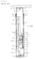
- FIG. 4 is a partial longitudinal cross-sectional view showing an embodiment of a telescopic member to which the present invention can apply.
- the telescopic member 1 of the present embodiment is attached to a table T by threadedly engaging and securing each of screw portions S formed on the corners of the table T so as to stick out downward therefrom with its screw hole 21a formed in the center of a disk-shaped end cap 21 welded to the upper end of an inner cylinder 2 having a cylindrical shape.
- the telescopic member 1 of the present invention may also be attached to a lower end portion of a leg that is preliminarily attached to the table T, without being directly attached to the table T.
- this arrangement eliminates the necessity for using a very long telescopic member 1.
- this arrangement makes it possible to apply the telescopic function to the table T at low costs.
- the telescopic member 1 is provided with an outer cylinder 3 that is externally fitted to the inner cylinder 2 so as to allow it freely slide therein.
- a bottom cap 31 made of synthetic resin, which has a short column shape, is attached to the lower end portion of the outer cylinder 3 with its half portion in the thickness direction being fitted therein. The diameter of the rest half portion is coincident with the outer diameter of the outer cylinder 3.
- a screw 32 is inserted through the center portion of bottom cap 31 from the bottom, and this is engaged with a screw hole 34a formed in a semi-circular base portion 34 of a pillar-shaped body 33 that is inserted into the inner cylinder 2 so that the base portion 34 is secured on the upper face of the bottom cap 31.
- the pillar-shaped body 33 is formed on the upper side of the base portion 34 so as to stick out therefrom, and that is allowed to freely slide in the longitudinal direction inside the inner cylinder 2 by a plurality of holding portions (not shown) sticking out from the inner circumference of the inner cylinder 2, and the upright portion 35 is provided with a plurality of engaging portions 36 in the form of holes appropriately spaced in the longitudinal direction (in the up-and-down direction in FIG. 4).
- a lock lever motion mechanism 22 Onto the inner circumference surface of the inner cylinder 2 facing these engaging portions 36 is attached a lock lever motion mechanism 22 that serves as a lock mechanism together with the engaging portions 36, with screws 23.
- the lock lever motion mechanism 22 is provided with a frame body 24 having a channel shape in its cross-section viewed from above or from below with its securing face to the inner cylinder 2 to be the center portion, and the open side of the channel shape of this frame body 24 is oriented toward the upright portion 35.
- a lock lever 25 which engages the engaging portions 36, is supported by a horizontal axis 26 in the front to rear direction in FIG. 4 so as to freely swing thereon in the center thereof.
- a pawl portion 25a that is one end on the lower side of the lock lever 25 is engaged with one of the engaging portions 36. The clockwise rotation of the lock lever 25 from the engaged state shown in FIG.
- the lock lever motion mechanism 22 is relatively raised together with the inner cylinder 2 with respect to the outer cylinder 3 so that the pawl portion 25a of the lock lever 25 is allowed to contact the upper end of the engaging portion 36 with which it currently engages.
- the lock lever 25 is allowed to rotate counterclockwise in FIG. 4 against the pressing force of the spring 28, with the result that it is released from the engagement with the engaging portion 36.
- the engagement of the lock lever 25 and the engaging portions 36 makes it possible to carry out a length adjusting operation of the telescopic member 1 based on the intervals in which the engaging portions 36 are placed.
- the lock lever motion mechanism 22 is raised beyond the uppermost engaging portion 36 together with the inner cylinder 2, the upper end portion of the slider 27 comes into contact with a control piece 37a that sticks out toward the lock lever motion mechanism 22 side at an appropriate position above the highest engaging portion 36.
- FIG. 5A which shows Embodiment 1 of the configuration of a telescopic member according to the present invention, is a partial longitudinal cross-sectional view seen from the right, which corresponds to FIG. 3A; and FIG. 5B is a partial cross-sectional view taken along line B-B of FIG. 5A.
- the telescopic member of the present embodiment has an arrangement in which the holding portions 29, installed integrally with the inner cylinder 2 of the conventional configuration, are provided as separate members from the inner cylinder 2 as holding bodies 90. Accordingly, the upright portion 35 of the pillar-shaped body 33 is modified in its lateral cross-section. Except this, the other arrangements and functions are the same as those of Figure 4 ; therefore, the same reference numerals are used and the detailed description thereof is omitted.
- each holding body 90 in its secured state, has a short pillar shape having an approximately T-letter shape when viewed from above or from below.
- a web portion of the T-letter shape forms a holding portion 91, and a flange portion forms a spacer portion 92 respectively.
- the holding portion 91 has a short square pillar shape with its protruding direction from the spacer portion 92 being coincident with its axial direction, and a slit having a predetermined length from the tip in the longitudinal direction is formed so as to be tow-legged.
- the gap between the leg portions is coincident with the thickness of the upright portion 35; thus, the upright portion 35 having an approximately W-letter shape in its lateral cross-section are supported with its both ends sandwiched by them.
- the rotation of the pillar-shaped body 33 secured by a screw 32 (see FIG. 4) on the axis in the longitudinal direction is regulated so that the pawl portion 25a and the engaging portion 36 are held in positions providing easy engagements between them.
- each holding body 90 is made of nylon resin so that no noise is generated at contact portions with the upright portion 35.
- the spacer portion 92 is curved into a concave shape toward the side bearing the holding portion 91 so that its rounded shape on the outer side is coincident with the inner circumferential surface of the outer cylinder 3 while its rounded shape on the inner side is coincident with the outer circumferential surface of the inner cylinder 2, so as to allow them to be respectively fitted thereto; thus, between the outer cylinder 3 and the inner cylinder 2 that are moved relatively, the curved surface on the outside of the spacer 92 is allowed to slide along the inner circumferential surface of the outer cylinder 3, with the result that a frictional force, exerted between these surfaces, is allowed to impart an appropriate resistant force to the relative movements, and also to maintain the inner cylinder 2 at the center position of the outer cylinder 3 in a concentric manner.
- these spacer portions 92 can replace the concentric-state maintaining function with respect to the outer cylinder 3 and the inner cylinder 2 carried out by the diameter-expanding portion located on the lower end portion of the inner cylinder 2 in the aforementioned conventional telescopic member 100, thereby making it possible to eliminate the diameter-expanding portion that tends to cause noise from its sliding along the inner circumferential surface of the outer cylinder 3.
- FIG. 6 is a perspective view that shows the essential portion of still another Embodiment (Embodiment 2) of a telescopic member according to the present invention.
- guide rails 95 serving as holding members by engaging the holding bodies 90 are attached to positions corresponding to the holding bodies 90 on the inner circumferential surface of the outer cylinder 3 of Embodiment 1.
- the other arrangements and functions are the same as those of the conventional configuration and Embodiment 1 ; therefore, he same reference numerals are used, and the detailed description thereof is omitted.
- a pair of guide rails 95 are placed on opposing positions on the inner circumferential surface of the outer cylinder 3 along the longitudinal direction.
- Each guide rail 95 is constituted by a plate-shape or rod-shape member that is elongated in the longitudinal direction, and stepped holes 95a are formed in two appropriate portions thereof so that they are secured on the inner circumferential surface of the outer cylinder 3 by screws 96 from inside through these stepped holes 95a.
- the upper and lower ends of the guide rail 95 may be welded to the inner circumferential surface of the outer cylinder 3; however, the present invention does not intend to limit the securing method of the guide rail 95, and any method may be used as long as it provides a sufficient strength that is resistant to a rotational moment that will be described later.
- FIG. 7 is a lateral cross-sectional view that shows the telescopic member of Embodiment 2 that is constituted by an outer cylinder in which a guide rail is assembled as a holding member.
- each guide rail 95 has a width smaller than the width of the holding portion 91 of the holding body 90, and is embedded along a groove formed in the outer side face of the spacer portion 92 in the longitudinal direction.
- one guide rail 95 is embedded to two holding bodies 90 aligned in the longitudinal direction so that the inner cylinder 2 is held from its rotation on the axis by the outer cylinder 3 together with the holding body 90. Therefore, for example, the rotational moment on the axis, applied to the inner cylinder 2 through the table T, is transmitted not to the pawl portion 25a of the lock lever motion mechanism 22 so as not to twist the pillar-shaped body 33 engaging this, but to guide rails 95 through the holding bodies 90 formed so as to penetrate the inner cylinder 2, and consequently to the outer cylinder 3.
- FIGS. 8A and 8B are perspective views that show the essential portion of still another Embodiment (Embodiment 3) of a telescopic member according to the present invention.
- the secured state and the shape of the guide rail 95 of Embodiment 2 to the outer cylinder 3 is modified. Except this fact, the other arrangements and functions are the same as those of the conventional configuration and Embodiment 2; therefore, the same reference numerals are used, and the detailed description thereof is omitted.
- each guide rail 95 is not secured to the inner circumferential surface of the outer cylinder 3 by the screws 96; instead of this, positioning pins 95b are respectively formed so as to stick out at the positions at which the stepped holes 95a are to be formed. Therefore, the securing process of the guide rail 95 to the inner circumferential surface of the outer cylinder 3 is made only by welding. In this case, since the tightening work for the screws 96 which is a comparatively difficult task in terms of space inside the outer cylinder 3 can be eliminated, it is possible to make the securing process easier.
- the guide rail 95 is shown as a flat-plate shape member in its entire shape in the same manner as Embodiment 2, it may be formed into an arc shape in its lateral cross-section that is aligned along the inner circumferential surface of the outer cylinder 3, for example, as illustrated in FIG. 12B; thus, various shapes may be adopted as the guide rail 95.
- FIG. 9A which shows the essential portion of still another Embodiment (Embodiment 4 of a telescopic member according to the present invention, is a partial longitudinal cross-sectional view seen from the right, which corresponds to FIG. 3A;
- FIG. 9B is a partial cross-sectional view taken along line C-C of FIG. 9A.
- a holding member which is installed as a separate member from the outer cylinder 3 like the guide rails 95 in Embodiment 3, is constituted integrally with the outer cylinder 3. Except this fact, the other arrangements and the functions are the same as those of the conventional configuration and Embodiment 3 ; therefore, the same reference numerals are used, and the detailed description thereof is omitted.
- protruding portions 97 are formed on the inner surface of the outer cylinder 3 in its length direction by means of stamping, etc. applied from the outside thereof, and by using these, the rotation of the holding bodies 90 is regulated in the same manner as the'guide rails 95 of Embodiment 3.
- the forming precision of pressing is comparatively low; therefore, in order to suppress instability in the rotational direction, it is more advantageous to provide the guide rails 95 as separate members from the outer cylinder 3, as shown in Embodiments 2 and 3.
- the outer cylinder 3 is covered with a cylindrical cover 8.
- This cover 8 is secured by a ring-shaped body, made of synthetic resin, interpolated in the gap to the outer cylinder 3 in a concentric manner with respect to the outer cylinder 3.
- the upper and lower end portions may be secured in a concentric manner with respect to the outer cylinder 3.
- Figure 10 is a partial cross-sectional view that shows still another Embodiment (Embodiment 5) of a telescopic member according to the present invention.
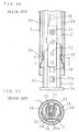
- FIG. 11 is a partial longitudinal cross-sectional view that shows a portion of a telescopic member disclosed by the present invention
- FIG. 12 is a cross-sectional side view seen from the left side.
- the base portion 34 and the upright portion. 35 of the pillar-shaped body 33 shown in Figure 4 are provided as separate parts.
- the base portion 34 is integrally provided with a stand-up portion 34b along one side face of the plate-shape upright portion 35 at the end of the securing side of the upright portion 35.
- Holes having the same diameter are respectively formed in the stand-up portion 34b and the lower end of the upright portion 35, and a rivet 38 is inserted through these holes so that the stand-up portion 34b and the upright portion 35 are connected by the rivet 38 so as to freely swing around the rivet 38.
- a washer 39 made of nylon, is attached to the rivet 38 between the stand-up portion 34b and the upright portion 35.
- the washer 39 may be formed by using another synthetic resin.
- the washer 39 may be omitted from this configuration.
- the base portion 34 is secured to a disk-shaped inner cap 81 welded to a position with a predetermined distance apart from the lower end of the outer cylinder 3, by using two screws 32.
- a male screw portion 82 is formed in the center of the inner cap 81 so as to stick out downward.
- an outer cap 83 made of metal having a diameter larger than that of the outer cylinder 3 is allowed to contact the lower end face of the outer cylinder 3 with its center portion formed into a recess portion dented upward, and a stepped hole is formed in this recess portion.
- This stepped hole is provided with a hole portion that has a large-diameter on the lower side, and a lock nut 84 is riveted into this hole portion on the larger-diameter side from below so that the male screw portion 82 of the aforementioned inner cap 81 is allowed to engage this from above.
- the telescopic member of the present disclosure has the above-mentioned arrangement; and those portions that are the same as the first Embodiment are indicated by the same reference numerals and the description thereof is omitted.
- the base portion 34 secured to the inner cap 81 and the upright portion 35 which is locked in its positional relationship with the inner circumferential surface of the inner cylinder 3 by the aforementioned holding portion (not shown) of the aforementioned Embodiment 1 are connected by the rivet 38; therefore, the dimensional dispersion in the individual members can be appropriately absorbed by the swinging movements around the rivet 38 as a rotational axis. Furthermore, since the washer'39 made of an elastic material is interpolated between the stand-up portion 34b and the upright portion 35 of the base portion 34, swinging movements in the directions orthogonal to the above-mentioned swinging directions are allowed so that the dimensional dispersion can be absorbed also in these directions.
- the arrangement of this disclosure may of course be applied to the telescopic member 1 of the aforementioned first Embodiment, as well as the telescopic member 100 of the conventional arrangement.
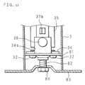
- FIG. 13 is a partial longitudinal cross-sectional view that shows an essential portion of another telescopic member disclosed by the present invention
- FIG. 14 is a cross-sectional side view seen from the left side.
- the inner cap 81 is protruded in its center portion downward by means of pressing and a female screw portion 81a is formed in the protruded portion.
- a male screw portion 831 which sticks out from the center portion of the upper face of the outer cap 83 made of synthetic resin having a disk-shape with a flat bottom, engages the female screw portion 81a from below, and the tip of the engaged male screw portion 831 is inserted through a perforation 341 formed in the corresponding position of the base portion 34.
- the outer cap 83 which has a diameter smaller than the outer diameter of the outer cylinder 3 and slightly larger than the inner diameter of the outer cylinder 3, is formed so as to have a round shape along its circumferential edge portion.
- the circumferential edge portion of the outer cap 83 has its upper half portion embedded into the inner diameter portion of the outer cylinder 3 along its entire circumference following the engagement of the male screw portion 831, so that the outer cap 83 is secured to the inner cap 81 while being closely in contact with the bottom end portion of the outer cylinder 3.
- the telescopic member of the present disclosure has the above-mentioned arrangement, and those portions that are the same as the above-mentioned disclosure are indicated by the same reference numerals and the description thereof is omitted.
- the secured state of the base portion 34 to the inner cap 81, as shown in FIG. 11 is improved. Except this fact, the other arrangements and functions are the same as those of the conventional configuration or Embodiment 12 ; therefore, the same reference numerals are used, and the detailed description is omitted.
- the base portion 34 having a semi-circular plate shape to the inner cap 81
- it is secured to the inner cap 81 by one stepped screw 86 from below the inner cap 81 at the center of the rounded shape of the base portion 34, that is, at the center axis of the outer cylinder 3.
- the stepped screw 86 which penetrates the inner cap 81 at a portion on the large-diameter side that is not threaded, also penetrates the rotary base 85 interpolated between the base portion 34 and the inner cap 81, and is threadedly engaged with the base portion 34 at the tip portion on the small-diameter side that is threaded.
- the rotary base 85 which has a disk shape with a penetration hole for the stepped screw 86 in the center, is formed from a material having an appropriate lubricating properties, such as a synthetic resin.
- the base portion 34 and the inner cap 81 are connected so as to freely rotate relatively on the axis of the outer cylinder 3.
- the pillar-shaped body 33 is allowed to release the rotational moment applied thereto through the relative rotation at this connecting portion, and free from twisting.
- the stepped screw 86 is used to connect the bottom cap 31 and the base portion 34 shown in FIG. 4, so that the rotary base 85 is placed between them; this arrangement may of course be adopted.
Landscapes
- Mutual Connection Of Rods And Tubes (AREA)
- Braking Arrangements (AREA)
- Pens And Brushes (AREA)
- Shaping By String And By Release Of Stress In Plastics And The Like (AREA)
- Materials For Medical Uses (AREA)
Applications Claiming Priority (9)
| Application Number | Priority Date | Filing Date | Title |
|---|---|---|---|
| JP36155398 | 1998-12-18 | ||
| JP36155398 | 1998-12-18 | ||
| JP468699 | 1999-01-11 | ||
| JP468699 | 1999-01-11 | ||
| JP21816299 | 1999-07-30 | ||
| JP21816299A JP3390367B2 (ja) | 1998-12-18 | 1999-07-30 | 伸縮部材 |
| JP30782899A JP3390381B2 (ja) | 1999-10-28 | 1999-10-28 | 伸縮部材及び成形体 |
| JP30782899 | 1999-10-28 | ||
| EP99403195A EP1013195B1 (de) | 1998-12-18 | 1999-12-17 | Teleskoporgan, zylindrischer Körper und Formkörper |
Related Parent Applications (1)
| Application Number | Title | Priority Date | Filing Date |
|---|---|---|---|
| EP99403195A Division EP1013195B1 (de) | 1998-12-18 | 1999-12-17 | Teleskoporgan, zylindrischer Körper und Formkörper |
Publications (2)
| Publication Number | Publication Date |
|---|---|
| EP1371306A2 true EP1371306A2 (de) | 2003-12-17 |
| EP1371306A3 EP1371306A3 (de) | 2004-04-28 |
Family
ID=27454138
Family Applications (2)
| Application Number | Title | Priority Date | Filing Date |
|---|---|---|---|
| EP99403195A Expired - Lifetime EP1013195B1 (de) | 1998-12-18 | 1999-12-17 | Teleskoporgan, zylindrischer Körper und Formkörper |
| EP03021022A Withdrawn EP1371306A3 (de) | 1998-12-18 | 1999-12-17 | Teleskoporgan, zylindrischer Körper und Formkörper |
Family Applications Before (1)
| Application Number | Title | Priority Date | Filing Date |
|---|---|---|---|
| EP99403195A Expired - Lifetime EP1013195B1 (de) | 1998-12-18 | 1999-12-17 | Teleskoporgan, zylindrischer Körper und Formkörper |
Country Status (6)
| Country | Link |
|---|---|
| US (1) | US6299113B1 (de) |
| EP (2) | EP1013195B1 (de) |
| CN (1) | CN1177557C (de) |
| AT (1) | ATE275846T1 (de) |
| DE (1) | DE69920150T2 (de) |
| ES (1) | ES2224575T3 (de) |
Cited By (1)
| Publication number | Priority date | Publication date | Assignee | Title |
|---|---|---|---|---|
| US10413077B2 (en) * | 2017-11-03 | 2019-09-17 | L&P Property Management Company | Anti-wobble adjustable bed leg assembly |
Families Citing this family (32)
| Publication number | Priority date | Publication date | Assignee | Title |
|---|---|---|---|---|
| EP1083388B1 (de) * | 1999-09-07 | 2004-02-18 | BSH Bosch und Siemens Hausgeräte GmbH | Teleskopgestänge für Haushaltsgeräte |
| SE0100423L (sv) * | 2001-02-12 | 2002-08-13 | Jaco Verken Ab | Glidlagring i teleskoprör och sätt att därmedelst undvika synliga repskador och glidmärken |
| MX2007003264A (es) | 2004-09-20 | 2007-10-11 | Joseph John Jingle | Soporte autoestable. |
| US7914238B2 (en) * | 2004-09-20 | 2011-03-29 | Anthony John Spencer Spearing | Free standing support |
| DK176598B1 (da) * | 2006-02-10 | 2008-10-20 | Jesper Oestergaard Kristensen | Teleskop löftesöjle til höjdeindstilling af eleverbare borde |
| TWI327657B (en) | 2006-03-16 | 2010-07-21 | Qisda Corp | Display panel and elevation adjusting base of the same |
| DK176810B1 (da) * | 2006-09-07 | 2009-10-12 | Falck Schmidt Defence Systems | Teleskopmast med reduceret slör |
| US20080203803A1 (en) * | 2007-02-27 | 2008-08-28 | Chi Paul Inhwan | Lumber Distraction Chair |
| KR100910946B1 (ko) * | 2007-09-17 | 2009-08-05 | 주식회사 한국가스스프링 | 실린더 안내를 위한 부싱 지지용 테이퍼 가이드를 갖는가스 실린더 |
| CN101769283B (zh) * | 2009-12-19 | 2012-08-22 | 凤城市申科实业有限公司 | 拉伸压缩、滑动定位支杆装置 |
| NL2004931C2 (nl) * | 2010-06-21 | 2011-12-22 | Resqtec Zumro B V | Veiligheidsinrichting. |
| CN102068138B (zh) * | 2010-11-19 | 2012-09-05 | 镇江浩博航空铁道设备研发有限公司 | 升降旋转结构 |
| WO2013086540A2 (en) * | 2011-12-10 | 2013-06-13 | Paper-Pak Industries | Patient transporter with expandable/deployable support structure |
| CN103362912B (zh) * | 2012-03-29 | 2016-09-07 | 海洋王(东莞)照明科技有限公司 | 伸缩结构、套筒及插接杆 |
| WO2014177229A1 (de) * | 2013-05-03 | 2014-11-06 | Kesseböhmer Produktions GmbH & Co. KG | Verriegelungsvorrichtung für teleskopierbare möbelsäule |
| EP2873344B1 (de) * | 2013-11-18 | 2017-04-19 | USM Holding AG | Möbel mit höhenverstellbarem Bein |
| CN104921502A (zh) * | 2015-06-11 | 2015-09-23 | 成都森绿家具有限公司 | 脚体螺旋式高度调节型沙发 |
| US11407557B2 (en) * | 2018-04-16 | 2022-08-09 | Charles G. Kiolbasa, Jr. | Shipping frame |
| US11407558B2 (en) * | 2018-04-16 | 2022-08-09 | Charles G. Kiolbasa, Jr. | Shipping frame and shield |
| CA3098944A1 (en) * | 2018-05-02 | 2019-11-07 | Linak A/S | Slider element for lifting columns |
| CN108412859B (zh) * | 2018-05-14 | 2023-07-28 | 苏州欧圣电气股份有限公司 | 拉杆装置及空压机 |
| NL2021684B1 (en) * | 2018-09-24 | 2020-05-07 | Koninklijke Ahrend B V | A height adjustable desk or table |
| US11584290B1 (en) * | 2018-12-04 | 2023-02-21 | Jared Smith | Dual purpose lift pedestal |
| JP7379151B2 (ja) * | 2019-04-12 | 2023-11-14 | Thk株式会社 | 多品種対応パレット装置、多品種対応パレット装置の制御システム |
| CN210330029U (zh) * | 2019-04-28 | 2020-04-17 | 革新(厦门)运动器材有限公司 | 一种折叠床支撑脚的支撑结构 |
| CN110848217A (zh) * | 2019-10-31 | 2020-02-28 | 杭州风行医疗器械有限公司 | 一种可双向卡顿的伸缩机构 |
| CN110863692B (zh) * | 2019-11-26 | 2021-05-14 | 广东美电国创科技有限公司 | 5g信号收发基站伸展运行方法 |
| USD1026633S1 (en) * | 2020-03-16 | 2024-05-14 | Dongguan Shichang Metals Factory Ltd. | Guide sleeve for height adjustable table |
| SE544482C2 (en) | 2020-12-29 | 2022-06-14 | Per Hoeglunds Innovation Ab | Adjustable telescopic leg with locking mechanism comprising a resilitently loaded fixating member |
| US11925267B2 (en) * | 2021-08-10 | 2024-03-12 | Zinus Inc. | Bed frame and support member for bed frame |
| DE102022105611A1 (de) | 2022-03-10 | 2023-09-14 | Leitz Acco Brands Gmbh & Co Kg | Höhenverstellbarer Hocker |
| CN114876979A (zh) * | 2022-03-30 | 2022-08-09 | 乐歌人体工学科技股份有限公司 | 一种升降桌用弹性伸缩配合传动杆组件 |
Citations (1)
| Publication number | Priority date | Publication date | Assignee | Title |
|---|---|---|---|---|
| JPS6238967A (ja) | 1985-08-14 | 1987-02-19 | Nec Corp | 送り仮名表記統一方式 |
Family Cites Families (19)
| Publication number | Priority date | Publication date | Assignee | Title |
|---|---|---|---|---|
| US2010306A (en) | 1933-03-02 | 1935-08-06 | Charles T Campbell | Adjustable stool and the like |
| US2710048A (en) | 1953-01-13 | 1955-06-07 | Rexford A Dawson | Furniture legs |
| DE1165350B (de) * | 1958-03-25 | 1964-03-12 | Leitz Ernst Gmbh | Geschlossene Fuehrung, insbesondere Zylinderfuehrung |
| DE1867557U (de) | 1962-12-13 | 1963-02-21 | Fritz Brucklacher | Hoehenverstellbarer saeulentisch. |
| GB1057955A (en) | 1963-11-07 | 1967-02-08 | Harry Krantz | Improved retention means for telescopic, spigot-and socket and like arrangements |
| SE378350B (de) | 1972-11-03 | 1975-09-01 | Skillingaryds Mekaniska Ab | |
| SE408287B (sv) | 1976-03-04 | 1979-06-05 | Nystrom Karl G | Anordning vid ett foretredesvis for uppberande av ett fordonssete avsett stativ |
| DE3216427A1 (de) * | 1982-05-03 | 1983-11-10 | Heinrich H. Klüssendorf GmbH & Co KG, 1000 Berlin | Einrichtung zur fuehrung zweier axial ineinander beweglicher stangen- oder/und roehrenartiger elemente |
| JPS63205300A (ja) | 1987-02-21 | 1988-08-24 | 今津 芳人 | 黄楊細工の着色方法 |
| JPH0219060A (ja) | 1988-07-07 | 1990-01-23 | Nec Corp | ファクシミリ装置 |
| US4867406A (en) | 1988-10-07 | 1989-09-19 | Eli Lengacher | Vertically adjustable chair support |
| GB2238572B (en) | 1989-11-20 | 1992-12-09 | Int Tutor Machines Limited | Locking collar |
| JPH0425003A (ja) | 1990-05-16 | 1992-01-28 | Seiko Epson Corp | 希土類、鉄系樹脂結合型磁石 |
| JPH0444117A (ja) | 1990-06-11 | 1992-02-13 | Seiko Instr Inc | 表示装置付き座標入力装置 |
| US5323695A (en) | 1991-04-17 | 1994-06-28 | Haworth, Inc. | Method of controlling height adjustable work station |
| DE29509264U1 (de) | 1994-10-24 | 1996-09-19 | MIT Moderne Industri Teknik ApS, Holbaek | Teleskopsäule |
| DK171962B1 (da) * | 1996-01-19 | 1997-09-01 | Ideassociates Ltd | Møbelben med teleskopisk forskydeligt afsnit |
| DE19745494A1 (de) | 1996-10-15 | 1998-05-20 | Harry Reinecke | Teleskopeinrichtung |
| DE29811921U1 (de) | 1998-07-04 | 1998-09-17 | Steinhilber, Helmut, Hergiswil | Teleskopischer Tischfuß |
-
1999
- 1999-12-13 US US09/459,571 patent/US6299113B1/en not_active Expired - Lifetime
- 1999-12-17 EP EP99403195A patent/EP1013195B1/de not_active Expired - Lifetime
- 1999-12-17 ES ES99403195T patent/ES2224575T3/es not_active Expired - Lifetime
- 1999-12-17 DE DE69920150T patent/DE69920150T2/de not_active Expired - Lifetime
- 1999-12-17 AT AT99403195T patent/ATE275846T1/de not_active IP Right Cessation
- 1999-12-17 EP EP03021022A patent/EP1371306A3/de not_active Withdrawn
- 1999-12-18 CN CNB991277759A patent/CN1177557C/zh not_active Expired - Fee Related
Patent Citations (1)
| Publication number | Priority date | Publication date | Assignee | Title |
|---|---|---|---|---|
| JPS6238967A (ja) | 1985-08-14 | 1987-02-19 | Nec Corp | 送り仮名表記統一方式 |
Cited By (1)
| Publication number | Priority date | Publication date | Assignee | Title |
|---|---|---|---|---|
| US10413077B2 (en) * | 2017-11-03 | 2019-09-17 | L&P Property Management Company | Anti-wobble adjustable bed leg assembly |
Also Published As
| Publication number | Publication date |
|---|---|
| CN1260153A (zh) | 2000-07-19 |
| EP1013195A3 (de) | 2001-01-03 |
| US6299113B1 (en) | 2001-10-09 |
| ATE275846T1 (de) | 2004-10-15 |
| EP1013195A2 (de) | 2000-06-28 |
| EP1371306A3 (de) | 2004-04-28 |
| CN1177557C (zh) | 2004-12-01 |
| EP1013195B1 (de) | 2004-09-15 |
| DE69920150T2 (de) | 2005-02-03 |
| DE69920150D1 (de) | 2004-10-21 |
| ES2224575T3 (es) | 2005-03-01 |
Similar Documents
| Publication | Publication Date | Title |
|---|---|---|
| EP1371306A2 (de) | Teleskoporgan, zylindrischer Körper und Formkörper | |
| US6581969B2 (en) | Buckle device | |
| BR112018009193B1 (pt) | Retentor de porta de veículo | |
| DE102009003746A1 (de) | Verbindungsvorrichtung für Fahrzeugsitze | |
| CN101104390B (zh) | 车辆用座椅 | |
| JPH01273749A (ja) | 支持高さ可変式ウエビング支持装置 | |
| DE3727784A1 (de) | Arbeitsstuhl mit verschwenkbarer sitzschale | |
| US3356327A (en) | Furniture leg | |
| JP2007118631A (ja) | アジャスタ兼キャスタ装置、キャスタ装置およびアジャスタ装置 | |
| US20010054863A1 (en) | Slide rail | |
| JPH0210747B2 (de) | ||
| JP3390381B2 (ja) | 伸縮部材及び成形体 | |
| KR20210055386A (ko) | 캐스터 | |
| US4247068A (en) | Extensible support apparatus | |
| KR200194041Y1 (ko) | 원위치 복귀형 회전의자용 지지체 | |
| JP3661560B2 (ja) | 椅子の背凭れ傾動機構におけるばねユニットの取付構造 | |
| JP7091049B2 (ja) | 肘掛け及び椅子 | |
| JP7302419B2 (ja) | ワークの位置決め機構 | |
| JP3687023B2 (ja) | 単柱テーブルにおける支柱構造 | |
| JPS6225991Y2 (de) | ||
| JP2005119389A (ja) | 車両用シートスライド装置のリテーナ構造 | |
| JPH0247873Y2 (de) | ||
| JPS6339335Y2 (de) | ||
| JP2001080378A (ja) | シフトレバーの支持装置 | |
| JPH0115820Y2 (de) |
Legal Events
| Date | Code | Title | Description |
|---|---|---|---|
| PUAI | Public reference made under article 153(3) epc to a published international application that has entered the european phase |
Free format text: ORIGINAL CODE: 0009012 |
|
| AC | Divisional application: reference to earlier application |
Ref document number: 1013195 Country of ref document: EP Kind code of ref document: P |
|
| AK | Designated contracting states |
Kind code of ref document: A2 Designated state(s): AT BE CH CY DE DK ES FI FR GB GR IE IT LI LU MC NL PT SE |
|
| RIC1 | Information provided on ipc code assigned before grant |
Ipc: 7A 47B 9/14 A Ipc: 7F 16B 7/14 B Ipc: 7A 47B 9/20 B |
|
| PUAL | Search report despatched |
Free format text: ORIGINAL CODE: 0009013 |
|
| AK | Designated contracting states |
Kind code of ref document: A3 Designated state(s): AT BE CH CY DE DK ES FI FR GB GR IE IT LI LU MC NL PT SE |
|
| 17P | Request for examination filed |
Effective date: 20041028 |
|
| AKX | Designation fees paid |
Designated state(s): DE GB IT NL |
|
| 17Q | First examination report despatched |
Effective date: 20041222 |
|
| STAA | Information on the status of an ep patent application or granted ep patent |
Free format text: STATUS: THE APPLICATION HAS BEEN WITHDRAWN |
|
| 18W | Application withdrawn |
Effective date: 20050208 |