EP1371428A2 - Antiparallelkurbelgetriebe für die Hub- und Senkbewegung der Abzugsvorrichtung an Strangpressanlagen - Google Patents
Antiparallelkurbelgetriebe für die Hub- und Senkbewegung der Abzugsvorrichtung an Strangpressanlagen Download PDFInfo
- Publication number
- EP1371428A2 EP1371428A2 EP03012995A EP03012995A EP1371428A2 EP 1371428 A2 EP1371428 A2 EP 1371428A2 EP 03012995 A EP03012995 A EP 03012995A EP 03012995 A EP03012995 A EP 03012995A EP 1371428 A2 EP1371428 A2 EP 1371428A2
- Authority
- EP
- European Patent Office
- Prior art keywords
- puller
- carriage
- main arm
- coupling
- lifting
- Prior art date
- Legal status (The legal status is an assumption and is not a legal conclusion. Google has not performed a legal analysis and makes no representation as to the accuracy of the status listed.)
- Granted
Links
Images


Classifications
-
- B—PERFORMING OPERATIONS; TRANSPORTING
- B21—MECHANICAL METAL-WORKING WITHOUT ESSENTIALLY REMOVING MATERIAL; PUNCHING METAL
- B21C—MANUFACTURE OF METAL SHEETS, WIRE, RODS, TUBES, PROFILES OR LIKE SEMI-MANUFACTURED PRODUCTS OTHERWISE THAN BY ROLLING; AUXILIARY OPERATIONS USED IN CONNECTION WITH METAL-WORKING WITHOUT ESSENTIALLY REMOVING MATERIAL
- B21C35/00—Removing work or waste from extruding presses; Drawing-off extruded work; Cleaning dies, ducts, containers, or mandrels for metal extruding
- B21C35/02—Removing or drawing-off work
Definitions
- the invention relates to an anti-parallel crank mechanism, which in a very advantageous manner Lifting and lowering movement of the trigger device (which is also referred to as a puller) Extrusion systems enabled.
- the trigger device which is also referred to as a puller
- Extrusion systems enabled.
- double pullers Application While the puller (this term is used in the following) in lowered Position has detected the press strand and moves, there is the mirror-like puller in a raised position.
- the anti-parallel crank mechanism is therefore for one puller, i.e. H. intended for a double puller.
- an extraction device on extrusion presses is known, two carriages being arranged to be movable on rails according to the prior art.
- Each carriage has grippers to grasp the workpiece ejected by the extrusion press and to move it on the runout of the extrusion system.
- the arms which represent the connection between the carriage and the grippers, each rotate about an axis.
- the arms are driven by a piston-cylinder unit.
- the grippers inevitably describe a section of a circular arc through the connection via the arms to the axis. Regardless of whether the arms are L-shaped or otherwise, the radius of the circular arc is always the distance from the center of the axis to the circular arc section on which the grippers move when lifting or lowering.
- a lifting drive is on the one hand on the carriage in the area the rail and on the other hand attached to the puller. With the help of the linear actuator, the lifting and Lowering movement of the puller realized.
- the puller is raised and lowered using the corresponding modules, the gripper, the clamping lamellae and the puller table, as well as other modules, such as a lever, which is placed in a certain position on the press strand and is used for error control.
- a lifting drive is used to raise and lower the puller.
- the puller is pivotably mounted up and down on the carriage using a main arm and a coupling, the bearings for the coupling and the main arm being arranged on the puller and on the carriage such that the coupling and the main arm are not in a parallel position to one another but are anti-parallel.
- the anti-parallelism of the position of the coupling and main arm is carried out by appropriate arrangement of the bearings such that the main arm and coupling cross in any position.
- the gripper thus describes a curve when lifting and lowering that deviates from a circular arc, which results in the advantages already mentioned for the system.
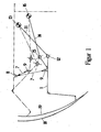
- the simplified representation shows the puller 1 using continuously drawn Lines in the lowered position, you can also say in the working position.
- Hydraulic cylinder 7 it can of course also be an equivalent assembly for lifting and lowering
- the puller 1 can be raised.
- the main arm 11 is on the one hand on a pillow block 13 and on the other hand on the puller 1 using the Bearing 12 attached.
- the coupling 14 is on the one hand on the pillow block 16 and on the other hand on Puller 1 attached using the bearing 15.
- main arm 11 and coupler 14 The antiparallel course of main arm 11 and coupler 14 is clearly shown in a raised position and shown in the lowered position.
- bearings 12 and 15 are located on puller 1
- the puller 1 has no "uniform" pivot point.
- the movement of the Pullers 1 does not form a circle around a fulcrum, but describes one of a section of a circular arc 18 deviating curve 19.
- the circular arc section 18 with the center - the pillow block 13 of the main arm 11 - shown.
- the puller 1 consists of the gripper 5, the mouth 6 of the gripper and others not shown here Assemblies such. B. the clamping slats.
- the main arm 11 for. B. consisting of square steel, using the Pillow block 13 attached to the carriage 3.
- the end of the main arm 11 facing the puller 1 is provided with a bearing holder, which serves to place the bearing 12.
- the coupling 14 consisting for example of flat steel, is antiparallel to the main arm 11, also attached to a pillow block 16 on the carriage 3.
- the other end of the coupling 14 is arranged movably on the puller 1 using the bearing 15.
- the hydraulic cylinder 7 is in another place arranged.
- the hydraulic cylinder 7 is shown purely schematically in FIG. 4, as is that Camp 9 on the puller and camp 10 on the car 3. It is a modified type the arrangement of the hydraulic cylinder 7. The movements when lifting and lowering the Pullers are the same as the one previously described.
- a puller was used in the exemplary embodiments. In practice, these are double-puller systems, with the second puller being designed in mirror image compared to the first. One puller is in the working position and the other puller is in the raised position.
Landscapes
- Engineering & Computer Science (AREA)
- Mechanical Engineering (AREA)
- Extrusion Of Metal (AREA)
- Hand Tools For Fitting Together And Separating, Or Other Hand Tools (AREA)
- Soil Working Implements (AREA)
- Pretreatment Of Seeds And Plants (AREA)
- Fertilizing (AREA)
- Harvesting Machines For Root Crops (AREA)
- Extrusion Moulding Of Plastics Or The Like (AREA)
Abstract
Description
Wie schon gesagt, dient ein Hubantrieb zum Heben und Senken des Pullers. Der Puller ist jedoch unter Verwendung eines Hauptarmes und einer Koppel auf-und abwärts schwenkbar am Wagen gelagert, wobei die Lager für die Koppel und dem Hauptarm am Puller und am Wagen derart angeordnet sind, daß die Koppel und der Hauptarm sich nicht in paralleler Stellung zueinander befinden, sondern antiparallel. Um die technische Aufgabe, wie sie vorher formuliert wurde, mit hohem Effekt zu lösen, ist die Antiparallelität der Stellung von Koppel und Hauptarm durch entsprechende Anordnung der Lager derart ausgeführt, daß sich Hauptarm und Koppel in jeder beliebigen Stellung kreuzen. Damit beschreibt der Greifer beim Heben und Senken eine Kurve, die von einem Kreisbogen abweicht, wobei sich die bereits genannten Vorteile für die Anlage ergeben.
Claims (5)
- Antiparallel-Kurbelgetriebe an Strangpressen unter Verwendung eines Hubanrtiebs (7) und eines Wagens (3), welcher an einer Schiene (2) verfahrbar angeordnet ist und mit dem Wagen (3) ein Puller (1) mit Greifer (5) verbunden ist, welcher mit Hilfe des Hubantriebs (7) eine Hub- und Senkbewegung ausführt, dadurch gekennzeichnet, daß eine mechanische Verbindung zwischen dem Wagen (3) und dem Puller (1) durch einen Hauptarm (11) und eine Koppel (14) gegeben ist, die Lagerung einerseits vom Hauptarm (11) und Koppel (14) am Wagen (3) und andererseits am Puller (1) so erfolgt, daß sich der Hauptarm (11) und die Koppel (14) in antiparalleler Stellung zueinander befinden und die Lager (12, 15) für den Hauptarm (11) und die Koppel (14) am Puller (1) so angeordnet sind, daß bei einer Hub- und Senkbewegung des Pullers (1) und damit des Greifers (5) im Bereich der Klemmlamellen dieser eine Kurve beschreibt, die von einer kreisbogenförmigen Bewegung zwischen den Positionen "angehoben" und "abgesenkt" bezogen auf die Lager (12, 13) des Hauptarms (11) und auf die Lager (15, 16) der Koppel (14) abweicht.
- Antiparallel-Kurbelgetriebe nach Anspruch 1, dadurch gekennzeichnet, daß der Hubantrieb (7) einerseits am Wagen (3) nahe der Schiene (2) gelagert ist und andererseits am Puller (1).
- Antiparallel-Kurbelgetriebe nach Anspruch 1, dadurch gekennzeichnet, daß der Hubantrieb (7) einerseits am Wagen (3) nahe dem Stehlager (16) für die Koppel (14) gelagert ist und andererseits am Puller (1).
- Antiparallel-Kurbelgetriebe nach Anspruch 1, dadurch gekennzeichnet, daß für die Verbindung vom Wagen (3) zum Puller (1) zwei Koppeln (14) verwendet werden, wobei in der Draufsicht betrachtet der Hauptarm (11) zwischen den beiden Koppeln (14) angeordnet ist.
- Antiparallel-Kurbelgetriebe nach Anspruch 1 bis 4, dadurch gekennzeichnet, daß in an sich bekannter Weise einem Puller (1) ein spiegelgleicher zweiter Puller (1) zugeordnet ist im Sinne eines Doppelpullersystems.
Applications Claiming Priority (2)
| Application Number | Priority Date | Filing Date | Title |
|---|---|---|---|
| DE10226139A DE10226139B4 (de) | 2002-06-12 | 2002-06-12 | Antiparallel-Kurbelgetriebe für Hub- und Senkbewegung der Abzugsvorrichtung an Strangpressanlagen |
| DE10226139 | 2002-06-12 |
Publications (3)
| Publication Number | Publication Date |
|---|---|
| EP1371428A2 true EP1371428A2 (de) | 2003-12-17 |
| EP1371428A3 EP1371428A3 (de) | 2004-07-28 |
| EP1371428B1 EP1371428B1 (de) | 2005-08-10 |
Family
ID=29557786
Family Applications (1)
| Application Number | Title | Priority Date | Filing Date |
|---|---|---|---|
| EP03012995A Expired - Lifetime EP1371428B1 (de) | 2002-06-12 | 2003-06-10 | Abzugsvorrichtung für Strangpressanlagen mit einem Antiparallelkurbelgetriebe für die Hub- und Senkbewegung |
Country Status (3)
| Country | Link |
|---|---|
| EP (1) | EP1371428B1 (de) |
| AT (1) | ATE301512T1 (de) |
| DE (2) | DE10226139B4 (de) |
Cited By (1)
| Publication number | Priority date | Publication date | Assignee | Title |
|---|---|---|---|---|
| CN105080994A (zh) * | 2015-07-29 | 2015-11-25 | 梁焯辉 | 一种高精度铝型材双牵引机 |
Families Citing this family (1)
| Publication number | Priority date | Publication date | Assignee | Title |
|---|---|---|---|---|
| DE102006028432B3 (de) * | 2006-06-16 | 2008-01-03 | Unterschütz Sondermaschinenbau GmbH | Abzugsvorrichtung an Strangpressanlagen mit modifizierter Hub- und Senkbewegung |
Family Cites Families (4)
| Publication number | Priority date | Publication date | Assignee | Title |
|---|---|---|---|---|
| DE2933262A1 (de) * | 1979-08-16 | 1981-02-26 | Elhaus Friedrich W | Ausziehvorrichtung fuer strangpressprofile |
| IT1214185B (it) * | 1987-05-22 | 1990-01-10 | Danieli Off Mecc | Dispositivo di traino estruso per pressa ad estrusione. |
| US5031436A (en) * | 1990-07-17 | 1991-07-16 | Granco-Clark, Inc. | Extrusion pulling with double puller lock |
| AT403258B (de) * | 1993-10-04 | 1997-12-29 | Reisch Ing Walter | Abzugsvorrichtung an strangpressen |
-
2002
- 2002-06-12 DE DE10226139A patent/DE10226139B4/de not_active Expired - Fee Related
-
2003
- 2003-06-10 EP EP03012995A patent/EP1371428B1/de not_active Expired - Lifetime
- 2003-06-10 DE DE50300936T patent/DE50300936D1/de not_active Expired - Fee Related
- 2003-06-10 AT AT03012995T patent/ATE301512T1/de not_active IP Right Cessation
Cited By (1)
| Publication number | Priority date | Publication date | Assignee | Title |
|---|---|---|---|---|
| CN105080994A (zh) * | 2015-07-29 | 2015-11-25 | 梁焯辉 | 一种高精度铝型材双牵引机 |
Also Published As
| Publication number | Publication date |
|---|---|
| EP1371428A3 (de) | 2004-07-28 |
| DE10226139B4 (de) | 2004-05-13 |
| DE10226139A1 (de) | 2004-01-08 |
| EP1371428B1 (de) | 2005-08-10 |
| ATE301512T1 (de) | 2005-08-15 |
| DE50300936D1 (de) | 2005-09-15 |
Similar Documents
| Publication | Publication Date | Title |
|---|---|---|
| DE8436125U1 (de) | Handhabungsroboter | |
| EP3186023B1 (de) | Radialpresse | |
| DE3629298A1 (de) | Rollengestell | |
| CH660093A5 (de) | Kabelkonfektionier-maschine. | |
| DE1201245B (de) | Vorrichtung zum Foerdern eines Werkstueckes | |
| EP0872293B1 (de) | Maschine zum Biegen von Rohren und Stangenmaterial | |
| EP3370890B1 (de) | Vorrichtung zum anstellen einer stauchwalze eines stauchgerüsts | |
| EP1371428B1 (de) | Abzugsvorrichtung für Strangpressanlagen mit einem Antiparallelkurbelgetriebe für die Hub- und Senkbewegung | |
| DE10047582B4 (de) | Scherenhubtisch | |
| WO2005110641A1 (de) | Vorrichtung zum schrittweisen verschieben von werkstücken | |
| DE3603650A1 (de) | Positioniervorrichtung | |
| DE3048738C2 (de) | Vorschubeinrichtung zum intermittierenden Drehen eines Kreissägeblattes | |
| EP1280622B1 (de) | Transfereinrichtung und verfahren zur steuerung einer transfereinrichtung | |
| DE102006028432B3 (de) | Abzugsvorrichtung an Strangpressanlagen mit modifizierter Hub- und Senkbewegung | |
| EP4335807A1 (de) | Aufnahmevorrichtung zur höhenvariablen aufnahme eines tragtellers | |
| DE19722879C2 (de) | Verfahren und Vorrichtung zum Kanten- oder Spießkanten von Walzprofilen, beispielsweise Knüppeln, um ihre Längsachse | |
| EP0023479A1 (de) | Vorrichtung zum Austausch von Stütz- oder Treibrollen einer Stranggiessanlage | |
| DE4210494B4 (de) | Hubeinrichtung | |
| DE4105824A1 (de) | Kettbaum-hubwagen zum wechseln von kettbaeumen mit steckachsenlagerung | |
| EP0693332B1 (de) | Presse mit Greiferschienen | |
| DE3613072C2 (de) | Greifervorrichtung zum lageweisen Erfassen und Umsetzen einer rechteckigen oder quadratischen Kastenschicht | |
| DE4237316A1 (de) | Einrichtung zum Umsetzen von Blechteilen in einer Pressenanlage | |
| DE102019122074A1 (de) | Werkstückabstützung und Verfahren zur Einrichtung und zum Betrieb einer Werkstückabstützung | |
| EP1201349B1 (de) | Vorrichtung zum Zu- und/oder Abführen von Radsätzen zu einer Radsatzpresse | |
| DE102018131932B3 (de) | Beschick - oder Entleerwagen |
Legal Events
| Date | Code | Title | Description |
|---|---|---|---|
| PUAI | Public reference made under article 153(3) epc to a published international application that has entered the european phase |
Free format text: ORIGINAL CODE: 0009012 |
|
| AK | Designated contracting states |
Kind code of ref document: A2 Designated state(s): AT BE BG CH CY CZ DE DK EE ES FI FR GB GR HU IE IT LI LU MC NL PT RO SE SI SK TR |
|
| AX | Request for extension of the european patent |
Extension state: AL LT LV MK |
|
| PUAL | Search report despatched |
Free format text: ORIGINAL CODE: 0009013 |
|
| AK | Designated contracting states |
Kind code of ref document: A3 Designated state(s): AT BE BG CH CY CZ DE DK EE ES FI FR GB GR HU IE IT LI LU MC NL PT RO SE SI SK TR |
|
| AX | Request for extension of the european patent |
Extension state: AL LT LV MK |
|
| 17P | Request for examination filed |
Effective date: 20040909 |
|
| GRAP | Despatch of communication of intention to grant a patent |
Free format text: ORIGINAL CODE: EPIDOSNIGR1 |
|
| RTI1 | Title (correction) |
Free format text: DRAWING-OFF DEVICE FOR AN EXTRUSION PRESS WITH AN ANTIPARALLEL CRANK GEARING FOR THE LIFTING AND LOWERING MOVEMENT |
|
| GRAS | Grant fee paid |
Free format text: ORIGINAL CODE: EPIDOSNIGR3 |
|
| AKX | Designation fees paid |
Designated state(s): AT BE BG CH CY CZ DE DK EE ES FI FR GB GR HU IE IT LI LU MC NL PT RO SE SI SK TR |
|
| GRAA | (expected) grant |
Free format text: ORIGINAL CODE: 0009210 |
|
| AK | Designated contracting states |
Kind code of ref document: B1 Designated state(s): AT BE BG CH CY CZ DE DK EE ES FI FR GB GR HU IE IT LI LU MC NL PT RO SE SI SK TR |
|
| PG25 | Lapsed in a contracting state [announced via postgrant information from national office to epo] |
Ref country code: EE Free format text: LAPSE BECAUSE OF FAILURE TO SUBMIT A TRANSLATION OF THE DESCRIPTION OR TO PAY THE FEE WITHIN THE PRESCRIBED TIME-LIMIT Effective date: 20050810 Ref country code: TR Free format text: LAPSE BECAUSE OF FAILURE TO SUBMIT A TRANSLATION OF THE DESCRIPTION OR TO PAY THE FEE WITHIN THE PRESCRIBED TIME-LIMIT Effective date: 20050810 Ref country code: SI Free format text: LAPSE BECAUSE OF FAILURE TO SUBMIT A TRANSLATION OF THE DESCRIPTION OR TO PAY THE FEE WITHIN THE PRESCRIBED TIME-LIMIT Effective date: 20050810 Ref country code: GB Free format text: LAPSE BECAUSE OF FAILURE TO SUBMIT A TRANSLATION OF THE DESCRIPTION OR TO PAY THE FEE WITHIN THE PRESCRIBED TIME-LIMIT Effective date: 20050810 Ref country code: NL Free format text: LAPSE BECAUSE OF FAILURE TO SUBMIT A TRANSLATION OF THE DESCRIPTION OR TO PAY THE FEE WITHIN THE PRESCRIBED TIME-LIMIT Effective date: 20050810 Ref country code: IE Free format text: LAPSE BECAUSE OF FAILURE TO SUBMIT A TRANSLATION OF THE DESCRIPTION OR TO PAY THE FEE WITHIN THE PRESCRIBED TIME-LIMIT Effective date: 20050810 Ref country code: SK Free format text: LAPSE BECAUSE OF FAILURE TO SUBMIT A TRANSLATION OF THE DESCRIPTION OR TO PAY THE FEE WITHIN THE PRESCRIBED TIME-LIMIT Effective date: 20050810 Ref country code: FI Free format text: LAPSE BECAUSE OF FAILURE TO SUBMIT A TRANSLATION OF THE DESCRIPTION OR TO PAY THE FEE WITHIN THE PRESCRIBED TIME-LIMIT Effective date: 20050810 Ref country code: RO Free format text: LAPSE BECAUSE OF FAILURE TO SUBMIT A TRANSLATION OF THE DESCRIPTION OR TO PAY THE FEE WITHIN THE PRESCRIBED TIME-LIMIT Effective date: 20050810 |
|
| REG | Reference to a national code |
Ref country code: GB Ref legal event code: FG4D Free format text: NOT ENGLISH |
|
| REG | Reference to a national code |
Ref country code: CH Ref legal event code: EP |
|
| REG | Reference to a national code |
Ref country code: IE Ref legal event code: FG4D Free format text: LANGUAGE OF EP DOCUMENT: GERMAN |
|
| REF | Corresponds to: |
Ref document number: 50300936 Country of ref document: DE Date of ref document: 20050915 Kind code of ref document: P |
|
| PG25 | Lapsed in a contracting state [announced via postgrant information from national office to epo] |
Ref country code: DK Free format text: LAPSE BECAUSE OF FAILURE TO SUBMIT A TRANSLATION OF THE DESCRIPTION OR TO PAY THE FEE WITHIN THE PRESCRIBED TIME-LIMIT Effective date: 20051110 Ref country code: SE Free format text: LAPSE BECAUSE OF FAILURE TO SUBMIT A TRANSLATION OF THE DESCRIPTION OR TO PAY THE FEE WITHIN THE PRESCRIBED TIME-LIMIT Effective date: 20051110 Ref country code: GR Free format text: LAPSE BECAUSE OF FAILURE TO SUBMIT A TRANSLATION OF THE DESCRIPTION OR TO PAY THE FEE WITHIN THE PRESCRIBED TIME-LIMIT Effective date: 20051110 Ref country code: BG Free format text: LAPSE BECAUSE OF FAILURE TO SUBMIT A TRANSLATION OF THE DESCRIPTION OR TO PAY THE FEE WITHIN THE PRESCRIBED TIME-LIMIT Effective date: 20051110 |
|
| REG | Reference to a national code |
Ref country code: CH Ref legal event code: NV Representative=s name: SCHMAUDER & PARTNER AG PATENTANWALTSBUERO |
|
| PG25 | Lapsed in a contracting state [announced via postgrant information from national office to epo] |
Ref country code: PT Free format text: LAPSE BECAUSE OF FAILURE TO SUBMIT A TRANSLATION OF THE DESCRIPTION OR TO PAY THE FEE WITHIN THE PRESCRIBED TIME-LIMIT Effective date: 20060110 |
|
| NLV1 | Nl: lapsed or annulled due to failure to fulfill the requirements of art. 29p and 29m of the patents act | ||
| PG25 | Lapsed in a contracting state [announced via postgrant information from national office to epo] |
Ref country code: HU Free format text: LAPSE BECAUSE OF FAILURE TO SUBMIT A TRANSLATION OF THE DESCRIPTION OR TO PAY THE FEE WITHIN THE PRESCRIBED TIME-LIMIT Effective date: 20060211 |
|
| GBV | Gb: ep patent (uk) treated as always having been void in accordance with gb section 77(7)/1977 [no translation filed] |
Effective date: 20050810 |
|
| REG | Reference to a national code |
Ref country code: IE Ref legal event code: FD4D |
|
| PGFP | Annual fee paid to national office [announced via postgrant information from national office to epo] |
Ref country code: AT Payment date: 20060606 Year of fee payment: 4 |
|
| PLBE | No opposition filed within time limit |
Free format text: ORIGINAL CODE: 0009261 |
|
| STAA | Information on the status of an ep patent application or granted ep patent |
Free format text: STATUS: NO OPPOSITION FILED WITHIN TIME LIMIT |
|
| PG25 | Lapsed in a contracting state [announced via postgrant information from national office to epo] |
Ref country code: MC Free format text: LAPSE BECAUSE OF NON-PAYMENT OF DUE FEES Effective date: 20060630 Ref country code: BE Free format text: LAPSE BECAUSE OF NON-PAYMENT OF DUE FEES Effective date: 20060630 |
|
| PGFP | Annual fee paid to national office [announced via postgrant information from national office to epo] |
Ref country code: IT Payment date: 20060630 Year of fee payment: 4 |
|
| 26N | No opposition filed |
Effective date: 20060511 |
|
| PG25 | Lapsed in a contracting state [announced via postgrant information from national office to epo] |
Ref country code: FR Free format text: LAPSE BECAUSE OF FAILURE TO SUBMIT A TRANSLATION OF THE DESCRIPTION OR TO PAY THE FEE WITHIN THE PRESCRIBED TIME-LIMIT Effective date: 20060811 |
|
| EN | Fr: translation not filed | ||
| PG25 | Lapsed in a contracting state [announced via postgrant information from national office to epo] |
Ref country code: DE Free format text: LAPSE BECAUSE OF NON-PAYMENT OF DUE FEES Effective date: 20070103 |
|
| PGFP | Annual fee paid to national office [announced via postgrant information from national office to epo] |
Ref country code: CZ Payment date: 20070504 Year of fee payment: 5 |
|
| PGFP | Annual fee paid to national office [announced via postgrant information from national office to epo] |
Ref country code: CH Payment date: 20070620 Year of fee payment: 5 |
|
| BERE | Be: lapsed |
Owner name: UNTERSCHUTZ SONDERMASCHINENBAU G.M.B.H. Effective date: 20060630 |
|
| PG25 | Lapsed in a contracting state [announced via postgrant information from national office to epo] |
Ref country code: AT Free format text: LAPSE BECAUSE OF NON-PAYMENT OF DUE FEES Effective date: 20070610 |
|
| PG25 | Lapsed in a contracting state [announced via postgrant information from national office to epo] |
Ref country code: LU Free format text: LAPSE BECAUSE OF NON-PAYMENT OF DUE FEES Effective date: 20060610 |
|
| PG25 | Lapsed in a contracting state [announced via postgrant information from national office to epo] |
Ref country code: CY Free format text: LAPSE BECAUSE OF FAILURE TO SUBMIT A TRANSLATION OF THE DESCRIPTION OR TO PAY THE FEE WITHIN THE PRESCRIBED TIME-LIMIT Effective date: 20050810 Ref country code: FR Free format text: LAPSE BECAUSE OF FAILURE TO SUBMIT A TRANSLATION OF THE DESCRIPTION OR TO PAY THE FEE WITHIN THE PRESCRIBED TIME-LIMIT Effective date: 20050810 |
|
| REG | Reference to a national code |
Ref country code: CH Ref legal event code: PL |
|
| PG25 | Lapsed in a contracting state [announced via postgrant information from national office to epo] |
Ref country code: CZ Free format text: LAPSE BECAUSE OF NON-PAYMENT OF DUE FEES Effective date: 20080610 |
|
| PG25 | Lapsed in a contracting state [announced via postgrant information from national office to epo] |
Ref country code: LI Free format text: LAPSE BECAUSE OF NON-PAYMENT OF DUE FEES Effective date: 20080630 Ref country code: ES Free format text: LAPSE BECAUSE OF NON-PAYMENT OF DUE FEES Effective date: 20060630 Ref country code: CH Free format text: LAPSE BECAUSE OF NON-PAYMENT OF DUE FEES Effective date: 20080630 |
|
| PG25 | Lapsed in a contracting state [announced via postgrant information from national office to epo] |
Ref country code: IT Free format text: LAPSE BECAUSE OF NON-PAYMENT OF DUE FEES Effective date: 20070610 |