EP1371469A2 - Verfahren zur Herstellung eines wärmeisolierten Leitungsrohres - Google Patents
Verfahren zur Herstellung eines wärmeisolierten Leitungsrohres Download PDFInfo
- Publication number
- EP1371469A2 EP1371469A2 EP03010530A EP03010530A EP1371469A2 EP 1371469 A2 EP1371469 A2 EP 1371469A2 EP 03010530 A EP03010530 A EP 03010530A EP 03010530 A EP03010530 A EP 03010530A EP 1371469 A2 EP1371469 A2 EP 1371469A2
- Authority
- EP
- European Patent Office
- Prior art keywords
- pentane
- inner tube
- outer tube
- annular gap
- tube
- Prior art date
- Legal status (The legal status is an assumption and is not a legal conclusion. Google has not performed a legal analysis and makes no representation as to the accuracy of the status listed.)
- Granted
Links
Images

Classifications
-
- B—PERFORMING OPERATIONS; TRANSPORTING
- B29—WORKING OF PLASTICS; WORKING OF SUBSTANCES IN A PLASTIC STATE IN GENERAL
- B29C—SHAPING OR JOINING OF PLASTICS; SHAPING OF MATERIAL IN A PLASTIC STATE, NOT OTHERWISE PROVIDED FOR; AFTER-TREATMENT OF THE SHAPED PRODUCTS, e.g. REPAIRING
- B29C44/00—Shaping by internal pressure generated in the material, e.g. swelling or foaming ; Producing porous or cellular expanded plastics articles
- B29C44/34—Auxiliary operations
- B29C44/3442—Mixing, kneading or conveying the foamable material
- B29C44/3446—Feeding the blowing agent
-
- B—PERFORMING OPERATIONS; TRANSPORTING
- B29—WORKING OF PLASTICS; WORKING OF SUBSTANCES IN A PLASTIC STATE IN GENERAL
- B29D—PRODUCING PARTICULAR ARTICLES FROM PLASTICS OR FROM SUBSTANCES IN A PLASTIC STATE
- B29D23/00—Producing tubular articles
-
- B—PERFORMING OPERATIONS; TRANSPORTING
- B29—WORKING OF PLASTICS; WORKING OF SUBSTANCES IN A PLASTIC STATE IN GENERAL
- B29C—SHAPING OR JOINING OF PLASTICS; SHAPING OF MATERIAL IN A PLASTIC STATE, NOT OTHERWISE PROVIDED FOR; AFTER-TREATMENT OF THE SHAPED PRODUCTS, e.g. REPAIRING
- B29C44/00—Shaping by internal pressure generated in the material, e.g. swelling or foaming ; Producing porous or cellular expanded plastics articles
- B29C44/20—Shaping by internal pressure generated in the material, e.g. swelling or foaming ; Producing porous or cellular expanded plastics articles for articles of indefinite length
- B29C44/32—Incorporating or moulding on preformed parts, e.g. linings, inserts or reinforcements
- B29C44/322—Incorporating or moulding on preformed parts, e.g. linings, inserts or reinforcements the preformed parts being elongated inserts, e.g. cables
-
- B—PERFORMING OPERATIONS; TRANSPORTING
- B29—WORKING OF PLASTICS; WORKING OF SUBSTANCES IN A PLASTIC STATE IN GENERAL
- B29C—SHAPING OR JOINING OF PLASTICS; SHAPING OF MATERIAL IN A PLASTIC STATE, NOT OTHERWISE PROVIDED FOR; AFTER-TREATMENT OF THE SHAPED PRODUCTS, e.g. REPAIRING
- B29C67/00—Shaping techniques not covered by groups B29C39/00 - B29C65/00, B29C70/00 or B29C73/00
- B29C67/24—Shaping techniques not covered by groups B29C39/00 - B29C65/00, B29C70/00 or B29C73/00 characterised by the choice of material
- B29C67/246—Moulding high reactive monomers or prepolymers, e.g. by reaction injection moulding [RIM], liquid injection moulding [LIM]
Definitions
- the invention relates to a method for producing a heat-insulated Conduit according to the preamble of claim 1.
- From DE 196 29 678 A1 discloses a method for producing a thermally insulated Conduit known, in which at least one inner tube from one to a Hose formed plastic film to form an annular gap-shaped cavity is enveloped and in the cavity a foamable plastic mixture on the base of polyurethane is input, which completely forms the cavity a thermally insulating foam fills.
- On the plastic film is a Outer tube made of a thermoplastic material as a mechanical protective layer extruded.
- the mixed together Components of polyurethane foam polyol and isocyanate of a spray gun fed to the intermixed components in the cavity injects.
- the components polyol and isocyanate are delivered in containers where the polyol and isocyanate are each separate from a mixing device be fed there mixed and forwarded the mixture to the spray gun becomes.
- foams which can be used as a material for thermal insulation in pipelines.
- the foam is made by reacting polyisocyanates, isocyanate-reactive compounds having a molecular weight of 500 to 8000 g / mol in the presence of blowing agents and catalysts. in which, blowing agent containing hydrocarbons having C 3 - or C 4 - rings are used which have a boiling point between 0 ° C and 75 ° C at a pressure of 1013 mbar.
- blowing agent containing hydrocarbons having C 3 - or C 4 - rings which have a boiling point between 0 ° C and 75 ° C at a pressure of 1013 mbar.
- the production of the foams is not described on a large scale in the laboratory scale.
- the present invention is based on the object mentioned above To improve the method of producing thermally insulated pipes, that carried out starting from the prior art, this cost can be and improved to a thermal barrier coating in the conduit with Thermal insulation properties leads. A narrower task is that the Propellant and air can be accurately metered in small quantities.
- FIG. 1 shows a side view of a device for producing heat-insulated Line pipe.
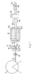
- Figure 2 shows the scheme of foam preparation.
- an inner tube 2 is continuously withdrawn.
- the Inner tube 2 is preferably a cross-linked polyethylene tube, in the wall of a Layer of polyvinyl alcohol is embedded.
- the inner tube 2 is replaced by a Caliber roller pair 3 out, whose roles are driven.
- the caliber roll pair 3 is in two mutually perpendicular directions transverse to the direction of manufacture slidably arranged.
- a film 5 is deducted from LLDPE and around the Inner tube 2 concentric with this to a slotted tube 6 with a glued or welded longitudinal seam shaped.
- a foamable plastic mixture based on polyurethane or polyethylene brought in.
- a gun 7 is used, from which the mixed with each other components are sprayed onto the film 5.
- message eaves 8 can be introduced.
- the closed tube is inserted into a mold 9, which consists of a plurality of mold halves 9a and 9b, which together form a " migratory shape" for the provided with the insulating layer and the film 5 inner tube 2.
- the film 5 facing surfaces of the mold halves 9a and 9b have a Wave profile, in which the film 5 is formed as a result of the foaming pressure.
- the emerging from the mold 9 tube 10 therefore has a corrugated Surface on.
- the tube 10 then passes through an X-ray device 11, with the help of the Tube 10 is continuously checked for an exactly central position of the inner tube 2. In case of a deviation, the pair of caliber rollers 3 is shifted accordingly.
- an outer sheath 13 made of plastic extruded, which is under the influence of a negative pressure in the corrugation of the tube 10th inserts.
- the outer shell glued because of his by the extrusion obtained high temperature with the plastic film. 5
- the finished tube 14 can then be withdrawn by means of a tape drive 15 and in a suitable device to be formed into a collar.
- the tube 14 is wound on a drum, not shown.
- the components pentane, for example cyclopentane, polyol and air are metered entered into a static mixer.
- the pentane is from a reservoir 16 via a three-piston diaphragm pump 1 7 the static mixer 18 fed.
- the Three-piston diaphragm pump 17 ensures a discharge line of 0.003 g / sec. to 4.4 g / sec. with an accuracy of 0.5%.
- a Mass flow meter 19 used.
- the polyol is removed from a storage tank 20 promoted by a gear pump 21, wherein the amount of polyol match Mass flow meter 22 is controlled.
- the air becomes a thermal mass controller 23 via a pressure intensifier promoted, which doses the air in an amount of 0.5 to 20 nl / h.
- the components premixed in the static mixer 18 become instantaneous behind the static mixer 18 arranged dynamic mixer 24 supplied. Due to the immediate vicinity of static mixer 18 and dynamic Mixer 24 will deposit the components d. H. a demixing of Components avoided.
- the isocyanate component is removed from a reservoir 25 by means of a pump 26 and a mass flow controller 27 introduced into the dynamic mixer 24 and there with the premixed components polyol, pentane and air to one high quality and very homogeneous foam processed continuously by means of Spray gun 7 in the annular gap between the inner tube 2 and the film 5 and the Outer tube 13 is introduced.
Landscapes
- Engineering & Computer Science (AREA)
- Mechanical Engineering (AREA)
- Casting Or Compression Moulding Of Plastics Or The Like (AREA)
- Thermal Insulation (AREA)
- Polyurethanes Or Polyureas (AREA)
- Extrusion Moulding Of Plastics Or The Like (AREA)
- Lining Or Joining Of Plastics Or The Like (AREA)
- Molding Of Porous Articles (AREA)
Abstract
Description
Claims (7)
- Verfahren zur Herstellung eines wärmeisolierten Leitungsrohres bestehend aus einem oder mehreren Innenrohren, einem im Abstand zu dem Innenrohr konzentrisch angeordneten Außenrohr und einer den Ringspalt zwischen Innenrohr und Außenrohr ausfüllenden Wärmedämmschicht auf der Basis von Polyurethan- oder Polyisocyanuratschaum, bei dem das Innenrohr in kontinuierlicher Arbeitsweise von dem Außenrohr umhüllt wird und der aufschäumbare Kunststoff in den Ringspalt eingebracht wird, dadurch gekennzeichnet, daß der Polyolkomponente kurz vor dem Zusammenmischen mit der Isocyanatkomponente ein flüssiges Treibmittel mittels einer Pumpe beigemischt wird.
- Verfahren nach Anspruch 1, dadurch gekennzeichnet, daß das Treibmittel Pentan ist.
- Verfahren nach Anspruch 1 oder 2, dadurch gekennzeichnet, daß der Polyolkomponente kurz vor dem Zusammenmischen mit der Isocyanatkomponente Luft zudosiert wird.
- Verfahren nach einem der Ansprüche 1 bis 3, dadurch gekennzeichnet, daß der Polyolkomponente, das Pentan und ggfs. die Luft in einem Statischmischer vermischt werden und dieses Gemisch mit der lsocyanatkomponente in einem dynamischen Mischer vermischt und das so hergestellte aufschäumbare Gemisch in den Ringspalt eingeführt wird.
- Verfahren nach einem der Ansprüche 1 bis 4, dadurch gekennzeichnet, daß das flüssige Pentan mittels einer pneumatischen Pumpe über eine Sicherheitsleitung von einem Vorratstank zu einer Dreikolbenmembranpumpe gefördert wird.
- Verfahren nach Anspruch 5, dadurch gekennzeichnet, daß das Pentan mittels der Dreikolbenmembranpumpe über einen hochflexiblen Schlauch in den Statischmischer gefördert wird.
- Verfahren nach einem der Ansprüche 1 bis 6, dadurch gekennzeichnet, daß das aus der Polyolkomponente und dem Pentan sowie ggfs. der Luft bestehende Gemisch sowie die lsocyanatkomponente mittels Zahnradpumpen dem dynamischen Mischer zugeführt werden.
Applications Claiming Priority (2)
| Application Number | Priority Date | Filing Date | Title |
|---|---|---|---|
| DE10226041A DE10226041A1 (de) | 2002-06-12 | 2002-06-12 | Verfahren zur Herstellung eines wärmeisolierten Leitungsrohres |
| DE10226041 | 2002-06-12 |
Publications (3)
| Publication Number | Publication Date |
|---|---|
| EP1371469A2 true EP1371469A2 (de) | 2003-12-17 |
| EP1371469A3 EP1371469A3 (de) | 2004-06-16 |
| EP1371469B1 EP1371469B1 (de) | 2006-03-22 |
Family
ID=29557775
Family Applications (1)
| Application Number | Title | Priority Date | Filing Date |
|---|---|---|---|
| EP03010530A Expired - Lifetime EP1371469B1 (de) | 2002-06-12 | 2003-05-10 | Verfahren zur Herstellung eines wärmeisolierten Leitungsrohres |
Country Status (9)
| Country | Link |
|---|---|
| EP (1) | EP1371469B1 (de) |
| JP (1) | JP2004017657A (de) |
| KR (1) | KR100967600B1 (de) |
| CN (1) | CN1319719C (de) |
| AT (1) | ATE320900T1 (de) |
| DE (2) | DE10226041A1 (de) |
| DK (1) | DK1371469T3 (de) |
| PL (1) | PL205745B1 (de) |
| RU (1) | RU2320484C2 (de) |
Cited By (3)
| Publication number | Priority date | Publication date | Assignee | Title |
|---|---|---|---|---|
| EP1719600A2 (de) | 2005-05-04 | 2006-11-08 | Coperion Werner & Pfleiderer GmbH & Co. KG | Anlage zur Erzeugung einer Schaumkunststoff-Folie |
| EP2305443A1 (de) | 2009-10-05 | 2011-04-06 | Afros S.P.A. | Verfahren und Vorrichtung zur Wärmeisolierung von Leitungen |
| EP4610037A1 (de) | 2024-03-01 | 2025-09-03 | Georg Fischer Rohrleitungssysteme AG | Rohrproduktion vorisolierter rohrstangen |
Families Citing this family (10)
| Publication number | Priority date | Publication date | Assignee | Title |
|---|---|---|---|---|
| DE102007015660A1 (de) * | 2007-03-31 | 2008-10-02 | Brugg Rohr Ag, Holding | Flexibles wärmeisoliertes Leitungsrohr |
| RU2366856C1 (ru) * | 2007-12-20 | 2009-09-10 | Евгений Владимирович Основин | Способ изготовления и монтажа составной теплоизоляционной оболочки трубопровода и трубопровод с составной теплоизоляционной оболочкой |
| EP2138751B1 (de) | 2008-06-28 | 2013-02-20 | Brugg Rohr AG, Holding | Verfahren zur Herstellung eines flexiblen wärmeisolierten Leitungsrohrs |
| LT2586602T (lt) | 2010-06-28 | 2018-12-27 | Obschestvo S Ogranichennoy Otvetstvennostiyu "Smit-Yartsevo" | Termoizoliacinio lankstaus vamzdžio gamybos būdas |
| LT2620268T (lt) | 2010-09-20 | 2017-01-25 | Obschestvo S Ogranichennoy Otvetstvennostiyu "Smit-Yartsevo" | Lankstaus vamzdžio su termine izoliacija gamybos linija |
| AU2013292168A1 (en) * | 2012-07-17 | 2015-02-05 | Basf Se | Method for continuous production of foams in tubes |
| CN105058680B (zh) * | 2015-08-25 | 2017-06-16 | 青岛科技大学 | 一种可升降式管路保护层同步定型装置 |
| CN105034238A (zh) * | 2015-08-25 | 2015-11-11 | 青岛科技大学 | 一种高效紧凑的管路保护层连续定型装置 |
| CN106493902A (zh) * | 2016-12-23 | 2017-03-15 | 湖南精正设备制造有限公司 | 一种压缩空气辅助的聚氨酯发泡装置 |
| CN114347523B (zh) * | 2021-12-22 | 2024-07-02 | 荥阳市坛山热力保温管道有限公司 | 一种保温管生产线 |
Family Cites Families (13)
| Publication number | Priority date | Publication date | Assignee | Title |
|---|---|---|---|---|
| US4211523A (en) * | 1978-11-29 | 1980-07-08 | Hoover Universal, Inc. | Gas-flow control apparatus for equipment for producing foamed plastic |
| DE3930824A1 (de) * | 1989-06-28 | 1991-02-28 | Bosch Siemens Hausgeraete | Hartschaumstoff sowie verfahren zur herstellung desselben |
| US5387618A (en) * | 1993-12-27 | 1995-02-07 | The Dow Chemical Company | Process for preparing a polyurethane foam in the presence of a hydrocarbon blowing agent |
| DE4418506A1 (de) * | 1994-05-27 | 1995-11-30 | Bayer Ag | Verfahren zur Herstellung von Formkörpern aus Zweikomponenten-Reaktivsystemen mit hohem Füllstoffgehalt |
| DE4422568C1 (de) * | 1994-06-28 | 1996-02-15 | Bayer Ag | Verfahren und Vorrichtung zur Schaumherstellung mittels unter Druck gelöstem Kohlendioxid |
| DE19524434A1 (de) * | 1995-07-05 | 1997-01-09 | Hennecke Gmbh Maschf | Verfahren und Vorrichtung zur Schaumherstellung mittels unter Druck gelöstem Kohlendioxid |
| DE4445140A1 (de) * | 1994-12-17 | 1996-06-20 | Basf Ag | Mit Kohlendioxid getriebener Schaum aus Styrolpolymeren |
| DE4446876A1 (de) * | 1994-12-27 | 1996-07-04 | Bayer Ag | Verfahren und Vorrichtung zur Schaumherstellung mittels unter Druck gelöstem Kohlendioxid |
| DE19622742C1 (de) * | 1996-06-07 | 1998-03-12 | Hennecke Gmbh | Verfahren zur Schaumherstellung mittels unter Druck gelöstem Kohlendioxid |
| KR100484042B1 (ko) * | 1996-07-23 | 2005-07-18 | 브루그 로드 아게, 홀딩 | 단열도관의제조방법 |
| DE19629678A1 (de) * | 1996-07-23 | 1998-01-29 | Brugg Rohrsysteme Gmbh | Verfahren zur Herstellung eines wärmeisolierten Leitungsrohres |
| DE19708570A1 (de) * | 1997-03-03 | 1998-09-10 | Basf Ag | Verfahren zur Herstellung von Schaumstoffen enthaltend Polyisocyanat-Polyadditionsprodukte |
| JP2000128951A (ja) * | 1998-10-26 | 2000-05-09 | Sumitomo Bayer Urethane Kk | 硬質ポリウレタンフォームの製造方法 |
-
2002
- 2002-06-12 DE DE10226041A patent/DE10226041A1/de not_active Withdrawn
-
2003
- 2003-05-10 DE DE50302703T patent/DE50302703D1/de not_active Expired - Lifetime
- 2003-05-10 EP EP03010530A patent/EP1371469B1/de not_active Expired - Lifetime
- 2003-05-10 DK DK03010530T patent/DK1371469T3/da active
- 2003-05-10 AT AT03010530T patent/ATE320900T1/de active
- 2003-06-09 JP JP2003163182A patent/JP2004017657A/ja active Pending
- 2003-06-10 KR KR1020030036998A patent/KR100967600B1/ko not_active Expired - Fee Related
- 2003-06-11 PL PL360635A patent/PL205745B1/pl unknown
- 2003-06-11 CN CNB031386849A patent/CN1319719C/zh not_active Expired - Fee Related
- 2003-06-11 RU RU2003117471/12A patent/RU2320484C2/ru not_active IP Right Cessation
Cited By (4)
| Publication number | Priority date | Publication date | Assignee | Title |
|---|---|---|---|---|
| EP1719600A2 (de) | 2005-05-04 | 2006-11-08 | Coperion Werner & Pfleiderer GmbH & Co. KG | Anlage zur Erzeugung einer Schaumkunststoff-Folie |
| EP1719600A3 (de) * | 2005-05-04 | 2007-12-26 | Coperion Werner & Pfleiderer GmbH & Co. KG | Anlage zur Erzeugung einer Schaumkunststoff-Folie |
| EP2305443A1 (de) | 2009-10-05 | 2011-04-06 | Afros S.P.A. | Verfahren und Vorrichtung zur Wärmeisolierung von Leitungen |
| EP4610037A1 (de) | 2024-03-01 | 2025-09-03 | Georg Fischer Rohrleitungssysteme AG | Rohrproduktion vorisolierter rohrstangen |
Also Published As
| Publication number | Publication date |
|---|---|
| DE50302703D1 (de) | 2006-05-11 |
| DE10226041A1 (de) | 2003-12-24 |
| DK1371469T3 (da) | 2006-06-06 |
| PL205745B1 (pl) | 2010-05-31 |
| PL360635A1 (en) | 2003-12-15 |
| KR20030096002A (ko) | 2003-12-24 |
| ATE320900T1 (de) | 2006-04-15 |
| EP1371469A3 (de) | 2004-06-16 |
| EP1371469B1 (de) | 2006-03-22 |
| KR100967600B1 (ko) | 2010-07-05 |
| CN1495005A (zh) | 2004-05-12 |
| CN1319719C (zh) | 2007-06-06 |
| RU2320484C2 (ru) | 2008-03-27 |
| JP2004017657A (ja) | 2004-01-22 |
Similar Documents
| Publication | Publication Date | Title |
|---|---|---|
| EP1371469B1 (de) | Verfahren zur Herstellung eines wärmeisolierten Leitungsrohres | |
| DE69831870T2 (de) | Koaxialkabel und sein herstellungsverfahren | |
| EP1840444B1 (de) | Verfahren zur Herstellung eines Mantels für ein wärmeisoliertes Leitungsrohr | |
| DE19629678A1 (de) | Verfahren zur Herstellung eines wärmeisolierten Leitungsrohres | |
| EP3433093B1 (de) | Thermisch gedämmte mediumrohre mit hfo-haltigem zellgas | |
| DE69902693T2 (de) | Vorisolierte rohre und verfahren zu ihrer herstellung | |
| EP2786059B1 (de) | Verfahren zur herstellung von gedämmten mantelrohren im kontinuierlichen herstellungsprozess | |
| DE102015110401B4 (de) | Verfahren und Vorrichtung zur Beschichtung einer Rohrleitung | |
| EP3256770B1 (de) | Leitungsrohr mit thermischer dämmung | |
| DE3637459A1 (de) | Verfahren und vorrichtung zur herstellung von kunststoffprofilen mit einer fluorierten schicht | |
| EP2964996B1 (de) | Wärmegedämmtes gewelltes leitungsrohr | |
| DE3216463A1 (de) | Verfahren zum herstellen eines flexiblen fernwaermeleitungsrohres | |
| DE2700478C2 (de) | Verfahren zur Herstellung eines wärme- und schallisolierten Leitungsrohres | |
| DE4019202A1 (de) | Verfahren zum herstellen eines schaumstoffes aus thermoplastischem kunststoff | |
| DE3921523C1 (de) | ||
| DE19934693C2 (de) | Verfahren und Vorrichtung zur Herstellung von Polymerschäumen | |
| EP3630481B1 (de) | Verfahrung zur herstellung von gedämmten rohren | |
| DE29521767U1 (de) | Wärmegedämmtes Kunststoffrohr und Vorrichtung zu seiner Herstellung | |
| AT375296B (de) | Verfahren und vorrichtung zur herstellung von rohrfoermigen isolationsverkleidungen aus expandiertem kunststoff | |
| DE1924199A1 (de) | Verfahren und Geraet zur Rohrbeschichtung | |
| DD214570A1 (de) | Verfahren und vorrichtung zur kontinuierlichen herstellung aussenbeschichteter schlaeuche, insbesondere gewebeschlaeuche | |
| JPS6246333B2 (de) | ||
| DE1504422A1 (de) | Verfahren und Vorrichtung zur Herstellung von aus einem Schaumstoffkern mit einer Ummantelung aus Kunststoff bestehenden endlosen Profilen | |
| DE3306591A1 (de) | Verfahren zur herstellung einer rohrfoermigen isolierung |
Legal Events
| Date | Code | Title | Description |
|---|---|---|---|
| PUAI | Public reference made under article 153(3) epc to a published international application that has entered the european phase |
Free format text: ORIGINAL CODE: 0009012 |
|
| AK | Designated contracting states |
Kind code of ref document: A2 Designated state(s): AT BE BG CH CY CZ DE DK EE ES FI FR GB GR HU IE IT LI LU MC NL PT RO SE SI SK TR |
|
| AX | Request for extension of the european patent |
Extension state: AL LT LV MK |
|
| RAP1 | Party data changed (applicant data changed or rights of an application transferred) |
Owner name: BRUGG ROHR AG, HOLDING |
|
| PUAL | Search report despatched |
Free format text: ORIGINAL CODE: 0009013 |
|
| AK | Designated contracting states |
Kind code of ref document: A3 Designated state(s): AT BE BG CH CY CZ DE DK EE ES FI FR GB GR HU IE IT LI LU MC NL PT RO SE SI SK TR |
|
| AX | Request for extension of the european patent |
Extension state: AL LT LV MK |
|
| 17P | Request for examination filed |
Effective date: 20040525 |
|
| 17Q | First examination report despatched |
Effective date: 20040907 |
|
| AKX | Designation fees paid |
Designated state(s): AT BE BG CH CY CZ DE DK EE ES FI FR GB GR HU IE IT LI LU MC NL PT RO SE SI SK TR |
|
| GRAP | Despatch of communication of intention to grant a patent |
Free format text: ORIGINAL CODE: EPIDOSNIGR1 |
|
| GRAS | Grant fee paid |
Free format text: ORIGINAL CODE: EPIDOSNIGR3 |
|
| GRAA | (expected) grant |
Free format text: ORIGINAL CODE: 0009210 |
|
| AK | Designated contracting states |
Kind code of ref document: B1 Designated state(s): AT BE BG CH CY CZ DE DK EE ES FI FR GB GR HU IE IT LI LU MC NL PT RO SE SI SK TR |
|
| PG25 | Lapsed in a contracting state [announced via postgrant information from national office to epo] |
Ref country code: SI Free format text: LAPSE BECAUSE OF FAILURE TO SUBMIT A TRANSLATION OF THE DESCRIPTION OR TO PAY THE FEE WITHIN THE PRESCRIBED TIME-LIMIT Effective date: 20060322 Ref country code: RO Free format text: LAPSE BECAUSE OF FAILURE TO SUBMIT A TRANSLATION OF THE DESCRIPTION OR TO PAY THE FEE WITHIN THE PRESCRIBED TIME-LIMIT Effective date: 20060322 Ref country code: IE Free format text: LAPSE BECAUSE OF FAILURE TO SUBMIT A TRANSLATION OF THE DESCRIPTION OR TO PAY THE FEE WITHIN THE PRESCRIBED TIME-LIMIT Effective date: 20060322 Ref country code: SK Free format text: LAPSE BECAUSE OF FAILURE TO SUBMIT A TRANSLATION OF THE DESCRIPTION OR TO PAY THE FEE WITHIN THE PRESCRIBED TIME-LIMIT Effective date: 20060322 |
|
| REG | Reference to a national code |
Ref country code: GB Ref legal event code: FG4D Free format text: NOT ENGLISH |
|
| REG | Reference to a national code |
Ref country code: CH Ref legal event code: EP |
|
| REG | Reference to a national code |
Ref country code: CH Ref legal event code: NV Representative=s name: PA ALDO ROEMPLER |
|
| REG | Reference to a national code |
Ref country code: IE Ref legal event code: FG4D Free format text: LANGUAGE OF EP DOCUMENT: GERMAN |
|
| REF | Corresponds to: |
Ref document number: 50302703 Country of ref document: DE Date of ref document: 20060511 Kind code of ref document: P |
|
| PG25 | Lapsed in a contracting state [announced via postgrant information from national office to epo] |
Ref country code: MC Free format text: LAPSE BECAUSE OF NON-PAYMENT OF DUE FEES Effective date: 20060531 |
|
| REG | Reference to a national code |
Ref country code: DK Ref legal event code: T3 |
|
| GBT | Gb: translation of ep patent filed (gb section 77(6)(a)/1977) |
Effective date: 20060522 |
|
| PG25 | Lapsed in a contracting state [announced via postgrant information from national office to epo] |
Ref country code: BG Free format text: LAPSE BECAUSE OF FAILURE TO SUBMIT A TRANSLATION OF THE DESCRIPTION OR TO PAY THE FEE WITHIN THE PRESCRIBED TIME-LIMIT Effective date: 20060622 |
|
| PG25 | Lapsed in a contracting state [announced via postgrant information from national office to epo] |
Ref country code: ES Free format text: LAPSE BECAUSE OF FAILURE TO SUBMIT A TRANSLATION OF THE DESCRIPTION OR TO PAY THE FEE WITHIN THE PRESCRIBED TIME-LIMIT Effective date: 20060703 |
|
| REG | Reference to a national code |
Ref country code: SE Ref legal event code: TRGR |
|
| PG25 | Lapsed in a contracting state [announced via postgrant information from national office to epo] |
Ref country code: PT Free format text: LAPSE BECAUSE OF FAILURE TO SUBMIT A TRANSLATION OF THE DESCRIPTION OR TO PAY THE FEE WITHIN THE PRESCRIBED TIME-LIMIT Effective date: 20060822 |
|
| ET | Fr: translation filed | ||
| REG | Reference to a national code |
Ref country code: IE Ref legal event code: FD4D |
|
| PLBE | No opposition filed within time limit |
Free format text: ORIGINAL CODE: 0009261 |
|
| STAA | Information on the status of an ep patent application or granted ep patent |
Free format text: STATUS: NO OPPOSITION FILED WITHIN TIME LIMIT |
|
| 26N | No opposition filed |
Effective date: 20061227 |
|
| PG25 | Lapsed in a contracting state [announced via postgrant information from national office to epo] |
Ref country code: GR Free format text: LAPSE BECAUSE OF FAILURE TO SUBMIT A TRANSLATION OF THE DESCRIPTION OR TO PAY THE FEE WITHIN THE PRESCRIBED TIME-LIMIT Effective date: 20060623 |
|
| PG25 | Lapsed in a contracting state [announced via postgrant information from national office to epo] |
Ref country code: EE Free format text: LAPSE BECAUSE OF FAILURE TO SUBMIT A TRANSLATION OF THE DESCRIPTION OR TO PAY THE FEE WITHIN THE PRESCRIBED TIME-LIMIT Effective date: 20060322 |
|
| PG25 | Lapsed in a contracting state [announced via postgrant information from national office to epo] |
Ref country code: LU Free format text: LAPSE BECAUSE OF NON-PAYMENT OF DUE FEES Effective date: 20060510 Ref country code: HU Free format text: LAPSE BECAUSE OF FAILURE TO SUBMIT A TRANSLATION OF THE DESCRIPTION OR TO PAY THE FEE WITHIN THE PRESCRIBED TIME-LIMIT Effective date: 20060923 |
|
| REG | Reference to a national code |
Ref country code: CH Ref legal event code: PCAR Free format text: ALDO ROEMPLER PATENTANWALT;BRENDENWEG 11 POSTFACH 154;9424 RHEINECK (CH) |
|
| PG25 | Lapsed in a contracting state [announced via postgrant information from national office to epo] |
Ref country code: CY Free format text: LAPSE BECAUSE OF FAILURE TO SUBMIT A TRANSLATION OF THE DESCRIPTION OR TO PAY THE FEE WITHIN THE PRESCRIBED TIME-LIMIT Effective date: 20060322 |
|
| REG | Reference to a national code |
Ref country code: FR Ref legal event code: PLFP Year of fee payment: 14 |
|
| REG | Reference to a national code |
Ref country code: FR Ref legal event code: PLFP Year of fee payment: 15 |
|
| REG | Reference to a national code |
Ref country code: FR Ref legal event code: PLFP Year of fee payment: 16 |
|
| PGFP | Annual fee paid to national office [announced via postgrant information from national office to epo] |
Ref country code: NL Payment date: 20190524 Year of fee payment: 17 |
|
| PGFP | Annual fee paid to national office [announced via postgrant information from national office to epo] |
Ref country code: IT Payment date: 20190620 Year of fee payment: 10 Ref country code: FI Payment date: 20190527 Year of fee payment: 17 Ref country code: CZ Payment date: 20190502 Year of fee payment: 17 |
|
| PGFP | Annual fee paid to national office [announced via postgrant information from national office to epo] |
Ref country code: TR Payment date: 20190509 Year of fee payment: 17 Ref country code: FR Payment date: 20190524 Year of fee payment: 17 |
|
| PGFP | Annual fee paid to national office [announced via postgrant information from national office to epo] |
Ref country code: CH Payment date: 20190524 Year of fee payment: 17 |
|
| PGFP | Annual fee paid to national office [announced via postgrant information from national office to epo] |
Ref country code: GB Payment date: 20190524 Year of fee payment: 17 |
|
| PGFP | Annual fee paid to national office [announced via postgrant information from national office to epo] |
Ref country code: DK Payment date: 20200526 Year of fee payment: 18 Ref country code: DE Payment date: 20200526 Year of fee payment: 18 |
|
| PGFP | Annual fee paid to national office [announced via postgrant information from national office to epo] |
Ref country code: SE Payment date: 20200526 Year of fee payment: 18 |
|
| PGFP | Annual fee paid to national office [announced via postgrant information from national office to epo] |
Ref country code: AT Payment date: 20200522 Year of fee payment: 18 |
|
| REG | Reference to a national code |
Ref country code: FI Ref legal event code: MAE |
|
| REG | Reference to a national code |
Ref country code: NL Ref legal event code: MM Effective date: 20200601 |
|
| PG25 | Lapsed in a contracting state [announced via postgrant information from national office to epo] |
Ref country code: CZ Free format text: LAPSE BECAUSE OF NON-PAYMENT OF DUE FEES Effective date: 20200510 Ref country code: CH Free format text: LAPSE BECAUSE OF NON-PAYMENT OF DUE FEES Effective date: 20200531 Ref country code: FI Free format text: LAPSE BECAUSE OF NON-PAYMENT OF DUE FEES Effective date: 20200510 Ref country code: LI Free format text: LAPSE BECAUSE OF NON-PAYMENT OF DUE FEES Effective date: 20200531 |
|
| PG25 | Lapsed in a contracting state [announced via postgrant information from national office to epo] |
Ref country code: NL Free format text: LAPSE BECAUSE OF NON-PAYMENT OF DUE FEES Effective date: 20200601 |
|
| REG | Reference to a national code |
Ref country code: BE Ref legal event code: MM Effective date: 20200531 |
|
| GBPC | Gb: european patent ceased through non-payment of renewal fee |
Effective date: 20200510 |
|
| PG25 | Lapsed in a contracting state [announced via postgrant information from national office to epo] |
Ref country code: FR Free format text: LAPSE BECAUSE OF NON-PAYMENT OF DUE FEES Effective date: 20200531 Ref country code: GB Free format text: LAPSE BECAUSE OF NON-PAYMENT OF DUE FEES Effective date: 20200510 |
|
| PG25 | Lapsed in a contracting state [announced via postgrant information from national office to epo] |
Ref country code: BE Free format text: LAPSE BECAUSE OF NON-PAYMENT OF DUE FEES Effective date: 20200531 |
|
| PG25 | Lapsed in a contracting state [announced via postgrant information from national office to epo] |
Ref country code: IT Free format text: LAPSE BECAUSE OF NON-PAYMENT OF DUE FEES Effective date: 20200510 |
|
| REG | Reference to a national code |
Ref country code: DE Ref legal event code: R119 Ref document number: 50302703 Country of ref document: DE |
|
| REG | Reference to a national code |
Ref country code: DK Ref legal event code: EBP Effective date: 20210531 |
|
| REG | Reference to a national code |
Ref country code: SE Ref legal event code: EUG |
|
| REG | Reference to a national code |
Ref country code: AT Ref legal event code: MM01 Ref document number: 320900 Country of ref document: AT Kind code of ref document: T Effective date: 20210510 |
|
| PG25 | Lapsed in a contracting state [announced via postgrant information from national office to epo] |
Ref country code: AT Free format text: LAPSE BECAUSE OF NON-PAYMENT OF DUE FEES Effective date: 20210510 Ref country code: SE Free format text: LAPSE BECAUSE OF NON-PAYMENT OF DUE FEES Effective date: 20210511 |
|
| PG25 | Lapsed in a contracting state [announced via postgrant information from national office to epo] |
Ref country code: DK Free format text: LAPSE BECAUSE OF NON-PAYMENT OF DUE FEES Effective date: 20210531 Ref country code: DE Free format text: LAPSE BECAUSE OF NON-PAYMENT OF DUE FEES Effective date: 20211201 |
|
| PG25 | Lapsed in a contracting state [announced via postgrant information from national office to epo] |
Ref country code: TR Free format text: LAPSE BECAUSE OF NON-PAYMENT OF DUE FEES Effective date: 20200510 |