EP1371478A2 - Steifer Kern in zwei Teilen, zur Herstellung von Luftreifen - Google Patents
Steifer Kern in zwei Teilen, zur Herstellung von Luftreifen Download PDFInfo
- Publication number
- EP1371478A2 EP1371478A2 EP03016411A EP03016411A EP1371478A2 EP 1371478 A2 EP1371478 A2 EP 1371478A2 EP 03016411 A EP03016411 A EP 03016411A EP 03016411 A EP03016411 A EP 03016411A EP 1371478 A2 EP1371478 A2 EP 1371478A2
- Authority
- EP
- European Patent Office
- Prior art keywords
- core
- attachment
- fractions
- fraction
- main part
- Prior art date
- Legal status (The legal status is an assumption and is not a legal conclusion. Google has not performed a legal analysis and makes no representation as to the accuracy of the status listed.)
- Granted
Links
Images


Classifications
-
- B—PERFORMING OPERATIONS; TRANSPORTING
- B29—WORKING OF PLASTICS; WORKING OF SUBSTANCES IN A PLASTIC STATE IN GENERAL
- B29D—PRODUCING PARTICULAR ARTICLES FROM PLASTICS OR FROM SUBSTANCES IN A PLASTIC STATE
- B29D30/00—Producing pneumatic or solid tyres or parts thereof
- B29D30/06—Pneumatic tyres or parts thereof (e.g. produced by casting, moulding, compression moulding, injection moulding, centrifugal casting)
- B29D30/08—Building tyres
- B29D30/10—Building tyres on round cores, i.e. the shape of the core is approximately identical with the shape of the completed tyre
- B29D30/12—Cores
-
- B—PERFORMING OPERATIONS; TRANSPORTING
- B29—WORKING OF PLASTICS; WORKING OF SUBSTANCES IN A PLASTIC STATE IN GENERAL
- B29C—SHAPING OR JOINING OF PLASTICS; SHAPING OF MATERIAL IN A PLASTIC STATE, NOT OTHERWISE PROVIDED FOR; AFTER-TREATMENT OF THE SHAPED PRODUCTS, e.g. REPAIRING
- B29C35/00—Heating, cooling or curing, e.g. crosslinking or vulcanising; Apparatus therefor
- B29C35/02—Heating or curing, e.g. crosslinking or vulcanizing during moulding, e.g. in a mould
- B29C2035/0211—Heating or curing, e.g. crosslinking or vulcanizing during moulding, e.g. in a mould resistance heating
-
- B—PERFORMING OPERATIONS; TRANSPORTING
- B29—WORKING OF PLASTICS; WORKING OF SUBSTANCES IN A PLASTIC STATE IN GENERAL
- B29C—SHAPING OR JOINING OF PLASTICS; SHAPING OF MATERIAL IN A PLASTIC STATE, NOT OTHERWISE PROVIDED FOR; AFTER-TREATMENT OF THE SHAPED PRODUCTS, e.g. REPAIRING
- B29C33/00—Moulds or cores; Details thereof or accessories therefor
- B29C33/02—Moulds or cores; Details thereof or accessories therefor with incorporated heating or cooling means
Definitions
- the present invention relates to the manufacture of tires. More particularly, the present invention relates to a substantially rigid core used as a support for manufacturing a tire and as a means of molding the surface of the interior cavity of a tire.
- Patent application EP 0 666 165 describes a manufacturing machine which uses such a core as a support for manufacturing a tire. Such a core is dismantled at the end of each manufacture of a tire, then is reconstituted to serve as a support for the manufacture another tire. Such a core must withstand many assembly cycles and disassembly. The core must be very robust in order to guarantee a high level of geometric quality, as well as great durability over time of the geometric qualities despite the many manipulations of which it is the object. Furthermore, in the patent application EP 0 666 165, it is proposed to use a rim as a member for joining the various fractions of which such a nucleus necessarily consists.
- Such a rigid core is to define at least partially a manufacturing form for the inner surface of a tire.
- a nucleus consists of several fractions in order to be able to be extracted from inside a tire by the volume available inside the beads. It has a plurality of circumferentially adjacent fractions, arranged side by side side in contact against each other by their transverse faces.
- faces transverse ”the faces which go from one side to the other of the nucleus. In the example described, it is flat faces, which are parallel to the axis of the core, these characteristics not being limiting.
- Said transverse faces of at least a fraction converge radially outside the core.
- the invention proposes to produce each of these fractions in two distinct parts which meet each with their own requirements: a hooking part and a main part, integral with the hanging part.
- the main function of the main part is the molding of the surface interior of the tire.
- the main part therefore serves as a manufacturing form and molds the inner surface of a tire.
- the essential function of the hooking part is the joining of the different fractions to a member for joining said different fractions of which such a nucleus is made.
- Each of said fractions comprises a part for hooking to a member for securing said different fractions, said attachment portion being arranged at the radially inner end of each of the fractions.
- Said attachment part is carried out essentially in a first material chosen for its ability to withstand a large number of assembly and disassembly.
- the attachment part is designed to optimize the grip of each of the fractions by the rim and by the various other handling devices which may be provided on the grippers or on each of the core use stations.
- Each of said fractions also comprises a main part integral with said part attachment, made essentially of a second material different from the first material and chosen for its ability to be molded and its good thermal conductivity.
- the main part is made integral with said attachment portion, that is to say not functionally removable.
- the main part is made so as to optimize the molding and vulcanization of the tire and also in order to be as economical as possible to make because it is a room specific to each dimension of the tire, while the attachment part can be carried out following identical plans and design for several different tires.
- the raw tire blank can only be produced with great difficulty. exact form that vulcanization and molding will give it.
- the lower part of the bead may have a section which only approaches the final section.
- the part radially the lowest of the bead may, in the raw state, be located at a lower radial level than what we will get after molding.
- the extensions of the shells can scrape some the radially internal part of the beads of the tire.
- the extensions of the shells scrape off the still raw bead they take away a small part of rubber which will be removed from the tire blank. This little rubber part is pushed back inside the mold and is lost.
- this problem is solved by reserving for the part main the entire molding function, no surface of the hooking part having in this variant embodiment of the molding function.
- an intermediate face is arranged in direct extension, and radially towards the smallest radii, i.e. towards the inside of the core molding surface.
- This intermediate face is either arranged in a plane perpendicular to the axis of rotation, or forms a very large truncated cone, according to the shape and orientation of the molding part.
- the junction line between the hooking part and the main part is housed in this intermediate surface, which also prevents the appearance of any burr on the inner surface of the tire bead, due to rubber creep between hanging part and main part.
- Another advantage of this provision is that the part attachment, or more precisely all of the attachment parts of all the fractions, do not necessarily have to form a continuous surface since these attachment parts are not not tight.
- the invention provides a rigid core at least partially defining a manufacturing form for the inner surface of a tire, the core comprising a plurality of fractions circumferentially adjacent, arranged side by side in contact with each other by their transverse faces, said transverse faces of at least a fraction being convergent radially outside the core, each of said fractions comprising a hooking part with a unit for securing the various fractions, said attachment part being arranged at the radially inner end of each of the fractions, said attachment part being produced essentially made of a first material, said core comprising a main part integral with said attachment part, made essentially of a second material different from the first material, made integral with said attachment portion, and in which, considering the assembly fractions, sizing and configuration of the main part, the part of attachment, and of the connection of the main part to the attachment part are such that
- the invention proposes a rigid core at least partially defining a manufacturing form for the interior surface of a tire, the core comprising a plurality of circumferentially adjacent fractions, arranged side by side in contact with each other by their transverse faces, said transverse faces of at least one fraction being convergent radially outside the core, each of said fractions comprising a hooking part with a member for securing different fractions, said attachment portion being arranged at the radially inner end of each of the fractions, said core comprising a main part integral with said part attachment, made essentially of a flowable and good thermally conductive material, molded with at least one electrical resistance per fraction, fixed to promote conduction thermal.
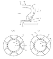
- a rigid core 1 according to the first embodiment.
- a plurality of fractions 10d, 10i circumferentially adjacent, arranged side by side in contact with each other by their transverse faces 10d1 and 10i1.
- the faces transverse 10il of at least a fraction 10i are convergent outside the core, in order to allow the disassembly of said core by removing this fraction radially from the inside.
- the kernel has two models of fractions: divergent fractions 10d, whose 10dl transverse faces are divergent outside the nucleus, and so-called “inverted” fractions 10i, the transverse faces 10il of which converge outside the core.
- the fractions will be designated by omitting the suffix i or d, for example "fraction 10", when their divergent or inverted character is of no importance for the technical aspect treated.
- Each of said fractions 10 comprises an attachment portion 12 to a rim 14, said portion attachment 12 being arranged at the radially inner end of each of the fractions.
- the rim 14 is circumferentially continuous.
- the parties attachment 12 since they are part of fractions 10, each develop only on one portion of a circle.
- Said attachment portion 12 is made essentially of a first material chosen for its ability to withstand a large number of assembly and disassembly cycles.
- Each of said fractions 10 comprises a main part 13 integral with said part attachment 12, the essential function of which is to define a manufacturing surface for the pneumatic.
- This main part 13 is made essentially of a second different material of the first material chosen for its ability to be molded, its good thermal conductivity and its lightness, made integral with said attachment portion 12, that is to say not removable functionally.
- a shell 15 which cooperates with the core 1 to define a cavity molding.
- the shell 15 ensuring the molding of the surface outer side of a tire side, in its radially inner part, a extension 140 which slides under the radially internal surface of the core. This allows to isolate and completely close the molding space before each shell has reached its position of closing. It is the most compact embodiment of the present invention.
- the attachment parts 12 have a contribution to the molding of the tire, since the line L1 separating the hooking part 12 from the main part 13 is in the molding cavity tire.
- FIG 3 we see a core 2 according to the second embodiment of the invention.
- a fraction 20 having a hooking part 22 and a main part 13, the part attachment 22 being mounted on a rim 24.
- the core 2 cooperates with a shell 25 (a shell for each side) to define a mold cavity.
- a shell 25 a shell for each side
- an intermediate face 21 arranged in direct extension of the molding surface on fraction 20, and radially towards the inside. This intermediate face 21 is located radially under the molding part of the fraction 20, and either is placed in a plane perpendicular to the axis of rotation (as illustrated), either forms a very large, very open angle cone.
- junction line L2 between the hooking part 22 and the main part 23 is housed in this intermediate surface 21, which also prevents the appearance of any burrs on the inner surface of the tire bead, due to rubber creep between hanging part and main part.
- such a core which contains parts with different coefficients of thermal expansion (steel for the part attachment and aluminum for the main part), accommodates thermal cycles caused by the manufacture of a tire.
- Such a core will be used at temperatures of around 150 ° C at least during vulcanization while during the production of the raw blank tire, it is used at temperatures below 100 ° C.
- a fraction 10, 20 always comprises a part attachment 12, 22 arranged radially to the inner part thereof. It has a part main 13, 23 made of molded light alloy.
- a main part 33 fixed to a hooking part 32 by means of screws 36 arranged laterally on either side of fraction 30, and circumferentially substantially in the middle part of the fraction.
- attachment spans are highly stressed at each assembly and at each disassembly of the core. This part is very resistant due to the choice of a suitable material.
- FIG. 6a it can be seen that zone 425 of the part attachment 42 extends radially opposite the bead B, so that the junction line L4 separating attachment part 42 and main part 43 appears on the interior surface of the tire bead B.
- the hooking parts form at least in the part molding the tire a continuous surface (see Figure 6b). This is not necessarily the case when the molding surface is entirely located on the main parts 53 (see FIG. 6d).
- a metal such as steel is typically used to make the attachment part.
- the steel is machined so as to obtain all the spans and shapes desired for this part hooking according to the hooking and handling purposes of the core.
- an electrical resistance 74 we see in Figure 7 an electrical resistance 74, the radial section revealing twelve sections of this resistance 74 which is bent so as to form back and forth of oriented sections circumferentially. So we use a flowable and good thermally conductive material, molded with at least one electrical resistance per fraction, embedded inside the wall forming the radially outer dome of each main part. Alternatively, one could also fix the resistors in a machined housing or fix them on the inside of said wall, in a way suitable for promoting thermal conduction.
- either a connector 75 is provided which allows, when docking with a gripper on a vulcanization station, to connect the core by another connector 76 at the vulcanization station of the machine to supply the electrical energy resistors and possibly to be able to connect measurement probes various, either inductive coupling means and / or any other means are provided for the same purpose usual coupling.
- FIGS. 5b and 7 an interesting alternative embodiment is seen comprising a rim 34 circumferentially continuous, the core comprising at least one attachment point on the side fraction, arranged on the attachment portion of each of the fractions, for example on a spout 37 arranged circumferentially.
- the core also has an attachment point on the rim side, complementary to the attachment side side, arranged on the rim and cooperating, to each fraction, with the attachment side on the fraction side to take up the efforts tending to radially separate the fractions from the rim, in cooperation with locking means not shown, for example means for axially pinching the rim 34 against the part attachment point 32.
- each attachment point on the rim side is also carried out on a spout 38 arranged circumferentially.
- said attachment side on the fraction side and attachment side on the rim are shaped so as to allow relative axial movement of the rim with respect to the assembly fractions in one direction only.
- rim spouts 38 34 we also see in this example that each attachment span is a frustoconical surface, said frustoconical surfaces being oriented axially on the same side of the core. More in particular, each frustoconical surface has a non-wedging angle.
- FIG 8 we recognize a fraction 80 having a hooking portion 82 and a main part 83.
- the core 8 cooperates with a shell 85 (a shell for each flank) to define a mold cavity.
- This variant shows a groove 840 arranged on each attachment portion 82, to cooperate with a rib 850 arranged on the shell 85, so to avoid any risk that the inverted fractions protrude in relation to the fractions divergent.
Landscapes
- Engineering & Computer Science (AREA)
- Mechanical Engineering (AREA)
- Moulds For Moulding Plastics Or The Like (AREA)
- Heating, Cooling, Or Curing Plastics Or The Like In General (AREA)
- Lining Or Joining Of Plastics Or The Like (AREA)
- Tyre Moulding (AREA)
- Tires In General (AREA)
- Materials For Medical Uses (AREA)
Applications Claiming Priority (3)
| Application Number | Priority Date | Filing Date | Title |
|---|---|---|---|
| FR9910420 | 1999-08-10 | ||
| FR9910420 | 1999-08-10 | ||
| EP00116695A EP1075929B1 (de) | 1999-08-10 | 2000-08-02 | Steifer Kern in zwei Teilen, zur Herstellung von Luftreifen |
Related Parent Applications (2)
| Application Number | Title | Priority Date | Filing Date |
|---|---|---|---|
| EP00116695.8 Division | 2000-08-02 | ||
| EP00116695A Division EP1075929B1 (de) | 1999-08-10 | 2000-08-02 | Steifer Kern in zwei Teilen, zur Herstellung von Luftreifen |
Publications (3)
| Publication Number | Publication Date |
|---|---|
| EP1371478A2 true EP1371478A2 (de) | 2003-12-17 |
| EP1371478A3 EP1371478A3 (de) | 2004-03-24 |
| EP1371478B1 EP1371478B1 (de) | 2010-04-14 |
Family
ID=9549093
Family Applications (3)
| Application Number | Title | Priority Date | Filing Date |
|---|---|---|---|
| EP03016411A Expired - Lifetime EP1371478B1 (de) | 1999-08-10 | 2000-08-02 | Steifer Kern in zwei Teilen, zur Herstellung von Luftreifen |
| EP03016412A Expired - Lifetime EP1371479B1 (de) | 1999-08-10 | 2000-08-02 | Steifer Kern in zwei Teilen, zur Herstellung von Luftreifen |
| EP00116695A Expired - Lifetime EP1075929B1 (de) | 1999-08-10 | 2000-08-02 | Steifer Kern in zwei Teilen, zur Herstellung von Luftreifen |
Family Applications After (2)
| Application Number | Title | Priority Date | Filing Date |
|---|---|---|---|
| EP03016412A Expired - Lifetime EP1371479B1 (de) | 1999-08-10 | 2000-08-02 | Steifer Kern in zwei Teilen, zur Herstellung von Luftreifen |
| EP00116695A Expired - Lifetime EP1075929B1 (de) | 1999-08-10 | 2000-08-02 | Steifer Kern in zwei Teilen, zur Herstellung von Luftreifen |
Country Status (5)
| Country | Link |
|---|---|
| US (1) | US6468062B1 (de) |
| EP (3) | EP1371478B1 (de) |
| JP (1) | JP4601784B2 (de) |
| AT (3) | ATE464174T1 (de) |
| DE (3) | DE60010989T2 (de) |
Families Citing this family (17)
| Publication number | Priority date | Publication date | Assignee | Title |
|---|---|---|---|---|
| JP4056290B2 (ja) | 2002-04-30 | 2008-03-05 | 株式会社ブリヂストン | 空気入りタイヤの製造方法および装置 |
| BR0211536B1 (pt) * | 2002-05-31 | 2011-06-28 | processo para fabricar um pneu e suporte toroidal para fabricar um pneu cru sobre o mesmo. | |
| EP1645404B1 (de) * | 2003-07-16 | 2013-08-21 | The Yokohama Rubber Co., Ltd. | Luftreifenherstellungsverfahren und reifenformtrommel |
| ATE407790T1 (de) | 2003-11-28 | 2008-09-15 | Pirelli | Verfahren zur herstellung von luftreifen und torusförmiger kern zur durchführung des verfahrens. |
| US20070125497A1 (en) * | 2005-12-02 | 2007-06-07 | Lundell Dennis A | Heated tire building core assembly and method |
| FR2921859B1 (fr) * | 2007-10-08 | 2011-05-20 | Michelin Soc Tech | Noyau rigide pour la fabrication des pneumatiques. |
| JP4297290B2 (ja) | 2007-12-21 | 2009-07-15 | 横浜ゴム株式会社 | 空気入りタイヤの製造方法 |
| US7910043B2 (en) * | 2007-12-21 | 2011-03-22 | The Goodyear Tire & Rubber Company | Tire building and cure station coupling apparatus and method |
| JP4407773B1 (ja) | 2009-05-07 | 2010-02-03 | 横浜ゴム株式会社 | 空気入りタイヤの製造方法 |
| JP4816761B2 (ja) | 2009-05-07 | 2011-11-16 | 横浜ゴム株式会社 | 空気入りタイヤの製造方法 |
| JP5261541B2 (ja) * | 2011-06-24 | 2013-08-14 | 住友ゴム工業株式会社 | 剛性中子 |
| JP5432955B2 (ja) * | 2011-06-24 | 2014-03-05 | 住友ゴム工業株式会社 | 剛性中子 |
| JP5492149B2 (ja) * | 2011-06-27 | 2014-05-14 | 住友ゴム工業株式会社 | 剛性中子、及びそれを用いたタイヤの製造方法 |
| JP5698694B2 (ja) * | 2012-03-19 | 2015-04-08 | 住友ゴム工業株式会社 | タイヤ形成用の剛性中子 |
| JP6242146B2 (ja) * | 2013-10-10 | 2017-12-06 | 住友ゴム工業株式会社 | タイヤ形成用の剛性中子、及びそれを用いたタイヤ製造方法 |
| JP5913266B2 (ja) * | 2013-11-27 | 2016-04-27 | 住友ゴム工業株式会社 | タイヤの製造方法 |
| US10441503B2 (en) | 2016-12-27 | 2019-10-15 | Richard T. FRENCH | SPA with temperature responsive pump activation and deactivation independent of heater activation |
Family Cites Families (18)
| Publication number | Priority date | Publication date | Assignee | Title |
|---|---|---|---|---|
| US1303256A (en) * | 1919-05-13 | of cleveland | ||
| US1249033A (en) * | 1914-07-03 | 1917-12-04 | Us Rubber Co | Mandrel for vulcanizing tire-shoes. |
| US1221349A (en) * | 1916-12-30 | 1917-04-03 | Robert M Merriman | Collapsible core. |
| US1389892A (en) * | 1919-03-19 | 1921-09-06 | Fisk Rubber Co | Collapsible core |
| US1810072A (en) * | 1926-10-04 | 1931-06-16 | Gen Tire & Rubber Co | Pneumatic tire and method of and apparatus for building the same |
| US1903458A (en) * | 1930-01-11 | 1933-04-11 | Frank L Johnson | Collapsible core |
| US1954764A (en) * | 1931-11-14 | 1934-04-10 | Gen Tire & Rubber Co | Tire building core |
| AT338637B (de) * | 1975-03-24 | 1977-09-12 | Polyair Maschinenbau Gmbh | Giess- oder spritzform zur herstellung von reifen |
| US4083672A (en) * | 1977-03-28 | 1978-04-11 | The Firestone Tire & Rubber Company | Automatic hub and apparatus for disassembly of the hub |
| DE2900565A1 (de) * | 1979-01-09 | 1980-07-17 | Bayer Ag | Verfahren und vorrichtung zur reifenentformung bei segmentierten kernen |
| FR2460200A1 (fr) * | 1979-06-29 | 1981-01-23 | Michelin & Cie | Procede de fabrication de pneumatiques par moulage, et pneumatiques obtenus par ce procede |
| ES2025339B3 (es) * | 1986-04-25 | 1992-03-16 | Cie Generale Des Etablissements Michelin-Michelin & Cie | Molde rigido para el moldeado y la vulcanizacion de neumaticos. |
| FR2597783B1 (fr) | 1986-04-25 | 1988-08-26 | Michelin & Cie | Moule rigide pour le moulage et la vulcanisation de pneumatiques |
| IT1189672B (it) * | 1986-05-20 | 1988-02-04 | Firestone Int Dev Spa | Metodo per la realizzazione a caldo di pneumatici |
| FR2712229A1 (fr) * | 1993-11-12 | 1995-05-19 | Sedepro | Moule pour pneumatique, et procédé de moulage du pneumatique. |
| US6113833A (en) * | 1997-07-22 | 2000-09-05 | Bridgestone Corporation | Segmented toroidal core for manufacturing pneumatic tires |
| JP3770705B2 (ja) * | 1997-07-22 | 2006-04-26 | 株式会社ブリヂストン | タイヤ製造用内型 |
| JP4191293B2 (ja) * | 1998-10-05 | 2008-12-03 | 株式会社ブリヂストン | タイヤ加硫成形金型及びタイヤ加硫成形方法 |
-
2000
- 2000-08-02 EP EP03016411A patent/EP1371478B1/de not_active Expired - Lifetime
- 2000-08-02 AT AT03016411T patent/ATE464174T1/de not_active IP Right Cessation
- 2000-08-02 DE DE60010989T patent/DE60010989T2/de not_active Expired - Lifetime
- 2000-08-02 EP EP03016412A patent/EP1371479B1/de not_active Expired - Lifetime
- 2000-08-02 AT AT03016412T patent/ATE316861T1/de not_active IP Right Cessation
- 2000-08-02 AT AT00116695T patent/ATE267691T1/de not_active IP Right Cessation
- 2000-08-02 DE DE60044212T patent/DE60044212D1/de not_active Expired - Lifetime
- 2000-08-02 EP EP00116695A patent/EP1075929B1/de not_active Expired - Lifetime
- 2000-08-02 DE DE60025855T patent/DE60025855T2/de not_active Expired - Lifetime
- 2000-08-08 JP JP2000240295A patent/JP4601784B2/ja not_active Expired - Fee Related
- 2000-08-10 US US09/636,021 patent/US6468062B1/en not_active Expired - Lifetime
Also Published As
| Publication number | Publication date |
|---|---|
| EP1371479B1 (de) | 2006-02-01 |
| US6468062B1 (en) | 2002-10-22 |
| DE60010989T2 (de) | 2005-05-19 |
| EP1075929B1 (de) | 2004-05-26 |
| DE60044212D1 (de) | 2010-05-27 |
| EP1075929A1 (de) | 2001-02-14 |
| ATE464174T1 (de) | 2010-04-15 |
| EP1371478A3 (de) | 2004-03-24 |
| JP2001088143A (ja) | 2001-04-03 |
| EP1371479A3 (de) | 2004-03-24 |
| EP1371478B1 (de) | 2010-04-14 |
| ATE316861T1 (de) | 2006-02-15 |
| DE60010989D1 (de) | 2004-07-01 |
| DE60025855T2 (de) | 2006-09-14 |
| JP4601784B2 (ja) | 2010-12-22 |
| ATE267691T1 (de) | 2004-06-15 |
| EP1371479A2 (de) | 2003-12-17 |
| DE60025855D1 (de) | 2006-04-13 |
Similar Documents
| Publication | Publication Date | Title |
|---|---|---|
| EP1075929B1 (de) | Steifer Kern in zwei Teilen, zur Herstellung von Luftreifen | |
| EP1636006B1 (de) | Formvorrichtung zur herstellung von behältern aus thermoplastischem material | |
| CA2073604C (fr) | Moule pour pneumatique et procede de moulage de pneumatique utilisant un tel moule | |
| EP0799722B1 (de) | Rad für Motorfahrzeuge und Verfahren zu dessen Herstellung | |
| WO1996033059A1 (fr) | Dispositif pour fabriquer des recipients en une matiere thermoplastique par soufflage ou etirage-soufflage | |
| WO2015019137A1 (fr) | Moule pour pneumatique comportant un insert annulaire en plusieurs parties | |
| FR2947478A1 (fr) | Moule a secteurs a recul radial | |
| FR2951401A1 (fr) | Presse de vulcanisation | |
| FR3102084A1 (fr) | Procédé de fabrication d’une pièce en matériau composite | |
| CA2872974C (fr) | Dispositif pour manipuler des grappes en cire | |
| FR2948894A1 (fr) | Procede de surmoulage, et moule pour sa mise en oeuvre | |
| FR2667120A1 (fr) | Joint de transmission articule telescopique et procedes pour realiser un element a pistes de coullissement notamment pour un tel joint. | |
| FR2873671A1 (fr) | Anneau a double articulation pour le levage de charge | |
| EP2682257A1 (de) | Herstellungsverfahren und -vorrichtung von Verbundmaterialteilen durch RTM | |
| FR2459056A1 (fr) | Poids pour halteres et outillage pour sa fabrication | |
| EP1178496B1 (de) | Schaft-Isolator-Herstellungsverfahren | |
| EP1000728B1 (de) | Herstellung eines Stützkörpers | |
| FR2735094A1 (fr) | Rotor d'helicoptere | |
| EP1075928B1 (de) | Steifer Kern zur Herstellung von Luftreifen, enthaltend eine Befestigungsfelge | |
| EP2785517B1 (de) | Selbstverriegelnde reifenform mit einem kraftbegrenzungsmittel | |
| EP2950990B1 (de) | Formwerkzeug mit zwei hälften und mindestens einem schieber | |
| FR2884239A1 (fr) | Dispositif de levage d'un moteur a combustion | |
| EP0968802A1 (de) | Formwerkzeug und formgebendes Element zum Formen eines Einschnittes in einem Gegenstand aus Gummi | |
| FR2774032A1 (fr) | Jante de roue pour cycles et analogues | |
| EP3490787B1 (de) | Vulkanisationsform für reifen und formelemente zusammensetzungsverfahren. |
Legal Events
| Date | Code | Title | Description |
|---|---|---|---|
| PUAI | Public reference made under article 153(3) epc to a published international application that has entered the european phase |
Free format text: ORIGINAL CODE: 0009012 |
|
| AC | Divisional application: reference to earlier application |
Ref document number: 1075929 Country of ref document: EP Kind code of ref document: P |
|
| AK | Designated contracting states |
Kind code of ref document: A2 Designated state(s): AT BE CH CY DE DK ES FI FR GB GR IE IT LI LU MC NL PT SE |
|
| RIN1 | Information on inventor provided before grant (corrected) |
Inventor name: SOULALIOUX, ALAIN Inventor name: LADOUCE, JEAN-PIERRE |
|
| PUAL | Search report despatched |
Free format text: ORIGINAL CODE: 0009013 |
|
| AK | Designated contracting states |
Kind code of ref document: A3 Designated state(s): AT BE CH CY DE DK ES FI FR GB GR IE IT LI LU MC NL PT SE |
|
| RIC1 | Information provided on ipc code assigned before grant |
Ipc: 7B 29C 33/06 B Ipc: 7B 29D 30/12 A |
|
| RAP1 | Party data changed (applicant data changed or rights of an application transferred) |
Owner name: SEDEPRO |
|
| 17P | Request for examination filed |
Effective date: 20040924 |
|
| AKX | Designation fees paid |
Designated state(s): AT BE CH CY DE DK ES FI FR GB GR IE IT LI LU MC NL PT SE |
|
| RAP1 | Party data changed (applicant data changed or rights of an application transferred) |
Owner name: MANUFACTURE FRANCAISE DES PNEUMATIQUES MICHELIN |
|
| 17Q | First examination report despatched |
Effective date: 20060302 |
|
| RIC1 | Information provided on ipc code assigned before grant |
Ipc: B29D 30/12 20060101AFI20090910BHEP Ipc: B29C 33/02 20060101ALI20090910BHEP |
|
| GRAP | Despatch of communication of intention to grant a patent |
Free format text: ORIGINAL CODE: EPIDOSNIGR1 |
|
| GRAS | Grant fee paid |
Free format text: ORIGINAL CODE: EPIDOSNIGR3 |
|
| GRAA | (expected) grant |
Free format text: ORIGINAL CODE: 0009210 |
|
| AC | Divisional application: reference to earlier application |
Ref document number: 1075929 Country of ref document: EP Kind code of ref document: P |
|
| AK | Designated contracting states |
Kind code of ref document: B1 Designated state(s): AT BE CH CY DE DK ES FI FR GB GR IE IT LI LU MC NL PT SE |
|
| REG | Reference to a national code |
Ref country code: GB Ref legal event code: FG4D Free format text: NOT ENGLISH |
|
| REG | Reference to a national code |
Ref country code: CH Ref legal event code: EP |
|
| REG | Reference to a national code |
Ref country code: IE Ref legal event code: FG4D Free format text: LANGUAGE OF EP DOCUMENT: FRENCH |
|
| REF | Corresponds to: |
Ref document number: 60044212 Country of ref document: DE Date of ref document: 20100527 Kind code of ref document: P |
|
| REG | Reference to a national code |
Ref country code: NL Ref legal event code: VDEP Effective date: 20100414 |
|
| PG25 | Lapsed in a contracting state [announced via postgrant information from national office to epo] |
Ref country code: ES Free format text: LAPSE BECAUSE OF FAILURE TO SUBMIT A TRANSLATION OF THE DESCRIPTION OR TO PAY THE FEE WITHIN THE PRESCRIBED TIME-LIMIT Effective date: 20100725 Ref country code: NL Free format text: LAPSE BECAUSE OF FAILURE TO SUBMIT A TRANSLATION OF THE DESCRIPTION OR TO PAY THE FEE WITHIN THE PRESCRIBED TIME-LIMIT Effective date: 20100414 Ref country code: SE Free format text: LAPSE BECAUSE OF FAILURE TO SUBMIT A TRANSLATION OF THE DESCRIPTION OR TO PAY THE FEE WITHIN THE PRESCRIBED TIME-LIMIT Effective date: 20100414 |
|
| REG | Reference to a national code |
Ref country code: IE Ref legal event code: FD4D |
|
| PG25 | Lapsed in a contracting state [announced via postgrant information from national office to epo] |
Ref country code: FI Free format text: LAPSE BECAUSE OF FAILURE TO SUBMIT A TRANSLATION OF THE DESCRIPTION OR TO PAY THE FEE WITHIN THE PRESCRIBED TIME-LIMIT Effective date: 20100414 Ref country code: AT Free format text: LAPSE BECAUSE OF FAILURE TO SUBMIT A TRANSLATION OF THE DESCRIPTION OR TO PAY THE FEE WITHIN THE PRESCRIBED TIME-LIMIT Effective date: 20100414 |
|
| PG25 | Lapsed in a contracting state [announced via postgrant information from national office to epo] |
Ref country code: GR Free format text: LAPSE BECAUSE OF FAILURE TO SUBMIT A TRANSLATION OF THE DESCRIPTION OR TO PAY THE FEE WITHIN THE PRESCRIBED TIME-LIMIT Effective date: 20100715 Ref country code: CY Free format text: LAPSE BECAUSE OF FAILURE TO SUBMIT A TRANSLATION OF THE DESCRIPTION OR TO PAY THE FEE WITHIN THE PRESCRIBED TIME-LIMIT Effective date: 20100414 |
|
| PG25 | Lapsed in a contracting state [announced via postgrant information from national office to epo] |
Ref country code: IE Free format text: LAPSE BECAUSE OF FAILURE TO SUBMIT A TRANSLATION OF THE DESCRIPTION OR TO PAY THE FEE WITHIN THE PRESCRIBED TIME-LIMIT Effective date: 20100414 Ref country code: DK Free format text: LAPSE BECAUSE OF FAILURE TO SUBMIT A TRANSLATION OF THE DESCRIPTION OR TO PAY THE FEE WITHIN THE PRESCRIBED TIME-LIMIT Effective date: 20100414 Ref country code: PT Free format text: LAPSE BECAUSE OF FAILURE TO SUBMIT A TRANSLATION OF THE DESCRIPTION OR TO PAY THE FEE WITHIN THE PRESCRIBED TIME-LIMIT Effective date: 20100816 |
|
| PLBE | No opposition filed within time limit |
Free format text: ORIGINAL CODE: 0009261 |
|
| STAA | Information on the status of an ep patent application or granted ep patent |
Free format text: STATUS: NO OPPOSITION FILED WITHIN TIME LIMIT |
|
| BERE | Be: lapsed |
Owner name: MANUFACTURE FRANCAISE DES PNEUMATIQUES MICHELIN Effective date: 20100831 |
|
| 26N | No opposition filed |
Effective date: 20110117 |
|
| PG25 | Lapsed in a contracting state [announced via postgrant information from national office to epo] |
Ref country code: IT Free format text: LAPSE BECAUSE OF FAILURE TO SUBMIT A TRANSLATION OF THE DESCRIPTION OR TO PAY THE FEE WITHIN THE PRESCRIBED TIME-LIMIT Effective date: 20100414 Ref country code: MC Free format text: LAPSE BECAUSE OF NON-PAYMENT OF DUE FEES Effective date: 20100831 |
|
| REG | Reference to a national code |
Ref country code: CH Ref legal event code: PL |
|
| GBPC | Gb: european patent ceased through non-payment of renewal fee |
Effective date: 20100802 |
|
| PG25 | Lapsed in a contracting state [announced via postgrant information from national office to epo] |
Ref country code: CH Free format text: LAPSE BECAUSE OF NON-PAYMENT OF DUE FEES Effective date: 20100831 Ref country code: LI Free format text: LAPSE BECAUSE OF NON-PAYMENT OF DUE FEES Effective date: 20100831 |
|
| PG25 | Lapsed in a contracting state [announced via postgrant information from national office to epo] |
Ref country code: BE Free format text: LAPSE BECAUSE OF NON-PAYMENT OF DUE FEES Effective date: 20100831 |
|
| PG25 | Lapsed in a contracting state [announced via postgrant information from national office to epo] |
Ref country code: GB Free format text: LAPSE BECAUSE OF NON-PAYMENT OF DUE FEES Effective date: 20100802 |
|
| PG25 | Lapsed in a contracting state [announced via postgrant information from national office to epo] |
Ref country code: LU Free format text: LAPSE BECAUSE OF NON-PAYMENT OF DUE FEES Effective date: 20100802 |
|
| REG | Reference to a national code |
Ref country code: FR Ref legal event code: PLFP Year of fee payment: 16 |
|
| PGFP | Annual fee paid to national office [announced via postgrant information from national office to epo] |
Ref country code: DE Payment date: 20150821 Year of fee payment: 16 |
|
| PGFP | Annual fee paid to national office [announced via postgrant information from national office to epo] |
Ref country code: FR Payment date: 20150820 Year of fee payment: 16 |
|
| REG | Reference to a national code |
Ref country code: DE Ref legal event code: R119 Ref document number: 60044212 Country of ref document: DE |
|
| REG | Reference to a national code |
Ref country code: FR Ref legal event code: ST Effective date: 20170428 |
|
| PG25 | Lapsed in a contracting state [announced via postgrant information from national office to epo] |
Ref country code: FR Free format text: LAPSE BECAUSE OF NON-PAYMENT OF DUE FEES Effective date: 20160831 Ref country code: DE Free format text: LAPSE BECAUSE OF NON-PAYMENT OF DUE FEES Effective date: 20170301 |