EP1371776A2 - Calandre et procédé pour le fonctionnement d' un calandre - Google Patents
Calandre et procédé pour le fonctionnement d' un calandre Download PDFInfo
- Publication number
- EP1371776A2 EP1371776A2 EP03009655A EP03009655A EP1371776A2 EP 1371776 A2 EP1371776 A2 EP 1371776A2 EP 03009655 A EP03009655 A EP 03009655A EP 03009655 A EP03009655 A EP 03009655A EP 1371776 A2 EP1371776 A2 EP 1371776A2
- Authority
- EP
- European Patent Office
- Prior art keywords
- magnetic field
- roller
- field generating
- generating device
- calender
- Prior art date
- Legal status (The legal status is an assumption and is not a legal conclusion. Google has not performed a legal analysis and makes no representation as to the accuracy of the status listed.)
- Granted
Links
Images

Classifications
-
- D—TEXTILES; PAPER
- D21—PAPER-MAKING; PRODUCTION OF CELLULOSE
- D21G—CALENDERS; ACCESSORIES FOR PAPER-MAKING MACHINES
- D21G1/00—Calenders; Smoothing apparatus
- D21G1/0073—Accessories for calenders
- D21G1/008—Vibration-preventing or -eliminating devices
-
- D—TEXTILES; PAPER
- D21—PAPER-MAKING; PRODUCTION OF CELLULOSE
- D21G—CALENDERS; ACCESSORIES FOR PAPER-MAKING MACHINES
- D21G1/00—Calenders; Smoothing apparatus
- D21G1/002—Opening or closing mechanisms; Regulating the pressure
- D21G1/004—Regulating the pressure
- D21G1/0053—Regulating the pressure using magnetic forces
Definitions
- the invention relates to a calender with several a roll stack arranged and a sensor arrangement, the one vibration of at least one roller detected.
- the invention further relates to a method to operate a calender with multiple rolls, the pressed against each other in a roll stack, whereby vibrations are determined on at least one roller.
- the invention is based on a calender explained, which is intended for treating a paper web is.
- the Paper web passed through the calender and in the nips, that are formed between adjacent calender rolls, with pressure and possibly with elevated temperature applied.
- calenders of this type act in many ways so-called “soft” rollers together with “hard” rollers. In some positions there are also two “soft” Rolling together.
- the soft rollers are included a plastic covering, which is more flexible than the surface of the hard rollers.
- the invention has for its object the barring formation to diminish.
- This task is performed on a calender of the type mentioned at the beginning Kind solved in that at least one roller has a controllable magnetic field generating device, which is a magnetic field acting on another roller depending on signals from the sensor arrangement generated.
- a magnetic field that acts on another roller creates Forces between those with the magnetic field generating device provided roller and the other roller. These forces do not have to be excessive. It So is not absolutely necessary, these forces like that to make it big, like they are used to pressurize the web of material are necessary. With the magnetically conditioned However, vibrations can be exerted by the roller is affected. This influence can fundamentally amplify the vibrations of the roller or weaken. You can therefore see it as one Measure before that the magnetic field generating device as a function of signals from the sensor arrangement a vibration in the calender is detected, is controlled.
- the application of a magnetic field to a roller is known per se from DE 195 07 828 C1.
- the magnetic field generating device but used the Forces that exert pressure on the material web are required to generate. This is the case with the present Invention as stated above is not required.
- the pressurizing forces can be generated in a conventional manner, for example through hydraulic support elements, which in one or both end rolls of the roll stack are provided are.
- the magnetic field generating device is used only to influence the vibration of the rollers to make the barring formation is reduced or even prevented.
- the magnetic field preferably acts on at least one Neighboring roller.
- the magnetic field preferably generates forces between the rollers, the resultant of which is essentially in Press direction is directed.
- the press direction is the direction in which the rollers are pressed against each other become.
- the rollers in relation to a plane in which the axes of rotation of the two End rollers are, are slightly offset. Out for this reason it is not necessary that the of Magnetic field generated forces exactly parallel to this Level. Small deviations are quite possible possible. Due to the mentioned orientation avoided the rollers from additional vibration is imprinted, which is an essential component perpendicular to the plane. This keeps the burden on the bearing arrangement in the stand of the calender small. Nevertheless, adequate vibration damping possible.
- At least two rollers each have a magnetic field generating device.
- vibrations that occur in the Calenders occur to dampen.
- the magnetic field generating devices can be controlled depending on each other are.
- the two magnetic field generating devices it is also possible to use the two magnetic field generating devices to be controlled so that the Repel magnetic fields.
- the first mode of operation to a slight increase in the compressive stress in the Nip leads between the two rollers, the latter leads Operating mode to a slight lowering the pressure in the nip. Both measures influence the treatment the material web in the nip practically not or not worth mentioning. But they are well suited to that Vibration behavior of the calender positive to influence that barring formation diminishes becomes.
- the magnetic field generating device preferably has a magnetic path that is a component has in the axial direction of the roller.
- the magnetic field can therefore close in the axial direction of the roller. This keeps magnetic losses through one larger air gap in the "return path" of the magnetic path could arise, small.
- the magnetic field generating device preferably acts to a predetermined length of the roller that is shorter than is the axial length of the roller.
- Magnetic fields in the axial direction are also sufficient are relatively short. If necessary, one can the axial length of the roller distributes several relatively provide short magnetic field generating devices that can be operated in the same or different ways. A force application or a force impact on you Area of the roller that is on a relatively short limited axial length, but still influences the vibration of the entire roller and thus one Influencing the vibration in the calender. Indeed requires a shorter magnetic field generating device even less electrical energy.
- the magnetic field generating device is preferably arranged in or on an intermediate roller.
- intermediate rolls usually have enough inside Space for accommodating the magnetic field generating device unlike finish rolls, which are due to hydraulic Support elements usually do not have enough space for a magnetic field generating device put.
- the magnetic field generating device preferably acts between roll neck. There is usually enough there Space available, so that the magnetic field generating device can be positioned without the Functionality of the rollers or the calender otherwise to hinder.
- the magnetic field generating device arranged axially within bearings in which the roller is stored.
- This training has the advantage that the magnetic field generating device caused on the rollers Forces cannot be dampened by the bearing. The forces rather act within a bounded by the camp Space directly on the rollers, so that possible Fights vibrations directly at the place where they originate can be.
- the magnetic field generating device is preferably arranged within a hollow roll shell. In order to the magnetic field generating device can be arranged there be where it works best. Magnetic losses are kept short.
- the magnetic field generating device which are usually designed as an electromagnet can be supplied easily because of a rotating union generally known for electrical supply lines is.
- the magnetic field generating device preferably has their influencing maximum at at least one position on which a natural vibration of the roller has an antinode.
- a magnetic field generating device is preferred for each antinode intended. Leave with it achieve the best damping effects.
- the task is in a method of the aforementioned Kind solved by using a magnetic field Additional forces between rollers depending generated by the determined vibrations.
- the vibrations are first determined, to which the calender is exposed. Here it is enough in in most cases, the vibrations on a single Determine roller. From these vibrations can you then derive control signals that are used for control the magnetic field generating device is used become. The magnetic field generating device generates then a magnetic field, which in turn forces the rollers exercises. These forces can now be controlled that they are the previously determined vibration in the calender counteract.
- the additional forces are preferably left on immediately the rollers work. So the additional forces are not introduced into the rollers via one or more bearings.
- rolling bearings allow vibrations to be initiated only up to a frequency of about 200 to 250 Hz. Vibrations that exceed the frequency are made by a roller bearing heavily subdued. If, on the other hand, you see the additional forces under Bypass the bearings by acting directly on the rollers leaves because the additional forces, so to speak, on the roll side Side of the bearings can then be generated one can also apply higher-frequency forces to the rollers and accordingly also higher-frequency vibrations fight.
- the additional forces between adjacent rollers can act. Between neighboring Rolling is the distance and therefore the magnetic one Air gap is the smallest, so with this approach the energy consumption is small. Can at the same time Relatively large forces can easily be generated. These forces only have to be so great that they are Counteract vibrations in the calender. The smaller the air gap to be overcome by the magnetic field, the more the mode of operation is cheaper.
- the additional forces are preferably left in a press plane Act.
- the vibrations are then mainly eliminated in the press plane. This will Position loads kept small perpendicular to the press plane.
- the additional forces are preferably left in dependence of the vibrations increasing or decreasing pressure act in a nip. So you don't need to an attraction due to the magnetic field or magnetic fields to exercise on adjacent rollers.
- the neighboring ones Rollers can also repel each other if this is for damping of the vibrations is favorable.
- the additional forces are preferably generated where an antinode of natural vibration of the roller is expected. As mentioned above, at least the position of the antinodes of the natural vibrations the roller with a relatively high reliability determine in advance. If you look at the additional forces there lets act where the vibration amplitude of the natural vibration is greater, then the dampening effect the strongest.
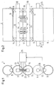
- a calender 1 shown only schematically has one Roll stack of five rolls 2-6, of which at least one roller carries an elastic cover.
- the rollers 2, 4, 6 are elastic Rolling, i.e. as rollers with an elastic coating educated. However, this is not shown in more detail.
- the two end rollers 2, 6 are as deflection adjustment rollers trained, i.e. they point out schematically shown hydrostatic or hydrodynamic support elements 7, 8 on, the facing forces produce. These forces in turn lead to pressures in the nips 9-12, through which a not shown Material web, for example a paper web, guided can be applied to there with increased pressures to become.
- the calender 1 can also be provided with heating rollers be, but are not shown in detail.
- the two upper center rolls 3, 4 are hollow rolls trained, i.e. the roller 3 has a roller shell 13, which is supported on a carrier 19 via bearings 15, 16 is.
- the roller 4 has a roller jacket 14 on which is supported on a carrier 20 via bearings 17, 18 is.
- the magnetic field generating device 21 is between the carrier 19 and the roll shell 13 .
- the magnetic field generating device 21 has a first one Electromagnet 21a and a second electromagnet 21b on the axial (based on the axial direction the roller 3) are offset from one another and opposite be excited to each other. This results in a magnetic indicated by arrows 22 Path in which a magnetic field is formed. It's closed recognize that the magnetic path 22 through the carrier 19 and the two electromagnets 21a, 21b. in the Carrier 19 and in the roll shell 13 can not in more detail measures shown can be provided to a prevent magnetic short circuit. It can e.g. around "air gap" inserts made of magnetic not act conductive material.
- roller 4 has a magnetic field generating device 23 on, the two axially to each other has offset electromagnets 23a, 23b, which also flow in opposite directions and a magnetic circuit 24 form, which closes by the carrier 20.
- vibration sensors on the lower intermediate roller 5 25 which is connected to a control device 26 are.
- the control device 26 now controls on the basis the signals of the vibration sensors 25, the magnetic field generating devices 21, 23 so that this Magnetic field generating devices 21, 23 magnetic fields and associated forces between the rollers 3, 4 generate that lead to a weakening or even to a Elimination of vibrations in the calender.
- the magnetic field generating devices 21, 23 are both operated so that the two rollers 3, 4 are tightened together. In this case the line load in the Nip 10 is increased slightly.
- the Magnetic field generating devices 21, 23 can, however also be operated so that the rollers 3, 4 repel each other. In this case, the line load in the Nip 10 slightly lowered.
- the magnetic field generating devices 21, 23 are from the control device 26 with electric currents fed. By controlling the currents you are in the Able to generate changing magnetic fields, the Magnetic fields in higher-frequency areas can swing. This "higher frequency” refers however to the operating frequency of the calender 1 or the speeds of the rollers 2-6. The frequencies of the Magnetic fields can range from 100 to 3,000 Hz are still quite manageable.
- the stationary magnetic field generating devices 21, 23 can also magnetic field generating devices provide that in not shown Rotate way together with the rollers 3, 4.
- the magnetic field generating devices in FIG Circumferential direction distributes several electromagnets, which then not only depends on the vibrations, which are determined via the vibration sensors 25, can be controlled, but also depending from their instantaneous angular position in relation to the neighboring roller. Nevertheless, these magnetic field generating devices should also then be controlled that the magnetic fields and the forces generated with them act essentially in the direction of the press, i.e. parallel to a plane that is the axis of rotation of the two End rollers 2, 6 connects together.
- the magnetic field generating devices it is also possible to use the magnetic field generating devices to be arranged outside the rollers 3, 4.
- FIGS. 3 and 4 show a further embodiment of a calender in which a magnetic field generating device between rollers 3, 4 21 is arranged.
- This Embodiment can be used both alone and in combination with the magnetic field generating device shown in FIGS. 1 and 2 be used.
- the magnetic field generating device acts 21 on roll neck 30, 31 of the intermediate rolls 3, 4, the roll journals 30, 31 mounted in bearings 34, 35 via roller bearings 32, 33 are.
- the carriers 34, 35 can be but in a known manner via lever in the chair of a calender.
- the magnetic field generating device 21 now acts axially within the roller bearings 32, 33 on the rollers 3, 4.
- the Magnetic field generating device 21 can with the carrier 34 of the upper intermediate roller 3 via a holder 36 be connected. So it remains when lowering the lower roller 4 in relative proximity to the roll neck 30 the upper roller 3 and then takes a distance to Roll neck 31 of the lower roller 4.
- the magnetic field generating device 21 is in FIG. 3 only shown schematically. Your magnetic field is 37 passed through a schematically illustrated yoke 38, that with pole shoes 39, 40 up to the immediate Extends near the pin 30, 31.
- the magnetic field generating device 21 with Power creates a magnetic field, that either attracts the roller journals 30, 31 to one another or repels each other.
- a correspondingly high Frequency of this application of force can be an additional Vibration exposure of the rollers 3, 4 realize that can be controlled so that vibrations, that are trained in the calender are fought.
- the vibration sensors required for this are 3 and 4 not shown in detail.
- each antinode or for several Antinodes of natural vibrations such Provide magnetic field generating device 21, 23 or that from the magnetic field generating means 21, 23 generated magnetic field so that the Effective maximum at the location of at least one antinode the natural vibration is present or on several antinodes.
- the antinodes of the natural vibration the corresponding roller 3, 4 can be in advance with calculate the necessary accuracy or simply estimate.
Landscapes
- Paper (AREA)
- Treatment Of Fiber Materials (AREA)
- Casting Or Compression Moulding Of Plastics Or The Like (AREA)
- Rolls And Other Rotary Bodies (AREA)
Applications Claiming Priority (2)
| Application Number | Priority Date | Filing Date | Title |
|---|---|---|---|
| DE2002121680 DE10221680C1 (de) | 2002-05-16 | 2002-05-16 | Kalander und Verfahren zum Betreiben eines Kalanders |
| DE10221680 | 2002-05-16 |
Publications (3)
| Publication Number | Publication Date |
|---|---|
| EP1371776A2 true EP1371776A2 (fr) | 2003-12-17 |
| EP1371776A3 EP1371776A3 (fr) | 2005-02-02 |
| EP1371776B1 EP1371776B1 (fr) | 2006-12-13 |
Family
ID=27816201
Family Applications (1)
| Application Number | Title | Priority Date | Filing Date |
|---|---|---|---|
| EP03009655A Expired - Lifetime EP1371776B1 (fr) | 2002-05-16 | 2003-04-30 | Calandre et procédé pour le fonctionnement d' un calandre |
Country Status (2)
| Country | Link |
|---|---|
| EP (1) | EP1371776B1 (fr) |
| DE (2) | DE10221680C1 (fr) |
Cited By (1)
| Publication number | Priority date | Publication date | Assignee | Title |
|---|---|---|---|---|
| WO2010094834A1 (fr) | 2009-02-20 | 2010-08-26 | Metso Paper, Inc. | Agencement pour amortissement de vibration dans une machine à toile fibreuse |
Families Citing this family (3)
| Publication number | Priority date | Publication date | Assignee | Title |
|---|---|---|---|---|
| FI119519B (fi) | 2007-06-27 | 2008-12-15 | Metso Paper Inc | Paperikoneen tela ja värähtelyn vaimennin |
| DE102007041725A1 (de) | 2007-09-04 | 2009-03-05 | Voith Patent Gmbh | Kalander und Kalanderzwischenwalze |
| DE102008026344A1 (de) | 2008-05-31 | 2009-12-03 | Voith Patent Gmbh | Verfahren zum Betreiben eines Kalanders und Kalander |
Family Cites Families (2)
| Publication number | Priority date | Publication date | Assignee | Title |
|---|---|---|---|---|
| DE19507828C1 (de) * | 1995-02-22 | 1996-03-28 | Rindfleisch Hans Jochen Dr Ing | Elektromagnetische Walzenanordnung zur Erzeugung eines Preßdrucks für die Behandlung von bahnförmigen Materialien |
| DE10008800B4 (de) * | 2000-02-25 | 2005-10-27 | Voith Paper Patent Gmbh | Verfahren zum Betrieb einer Kalanderwalze und Kalanderwalze |
-
2002
- 2002-05-16 DE DE2002121680 patent/DE10221680C1/de not_active Expired - Fee Related
-
2003
- 2003-04-30 EP EP03009655A patent/EP1371776B1/fr not_active Expired - Lifetime
- 2003-04-30 DE DE50305932T patent/DE50305932D1/de not_active Expired - Lifetime
Cited By (2)
| Publication number | Priority date | Publication date | Assignee | Title |
|---|---|---|---|---|
| WO2010094834A1 (fr) | 2009-02-20 | 2010-08-26 | Metso Paper, Inc. | Agencement pour amortissement de vibration dans une machine à toile fibreuse |
| EP2398961A4 (fr) * | 2009-02-20 | 2012-08-01 | Metso Paper Inc | Agencement pour amortissement de vibration dans une machine à toile fibreuse |
Also Published As
| Publication number | Publication date |
|---|---|
| EP1371776A3 (fr) | 2005-02-02 |
| EP1371776B1 (fr) | 2006-12-13 |
| DE10221680C1 (de) | 2003-10-09 |
| DE50305932D1 (de) | 2007-01-25 |
Similar Documents
| Publication | Publication Date | Title |
|---|---|---|
| DE69431492T2 (de) | Kalender zum Kalandrieren einer Papierbahn | |
| DE10008800B4 (de) | Verfahren zum Betrieb einer Kalanderwalze und Kalanderwalze | |
| DE19652769A1 (de) | Verfahren und Vorrichtung zur Dämpfung von Kontaktschwingungen | |
| DE69417197T2 (de) | Kalander | |
| DE3201635C2 (de) | Kalanderanordnung | |
| WO2022008129A1 (fr) | Système de revêtement et procédé de revêtement | |
| EP0949378A1 (fr) | Machine à rouleaux et son procédé de fonctionnement | |
| DE3119677A1 (de) | "maschinensuperkalander fuer papier oder dergleichen" | |
| EP1256731B1 (fr) | Rouleau à compensation de flèche | |
| EP1371776A2 (fr) | Calandre et procédé pour le fonctionnement d' un calandre | |
| DE3119691A1 (de) | Maschinen-superkalander fuer papier | |
| EP2737126A1 (fr) | Calandre | |
| DE10394020T5 (de) | Mehrwalzenkalander | |
| EP0928843B1 (fr) | Dispositif de pressage | |
| EP1162045A2 (fr) | Moyens de contrôle de température pour cylindres | |
| EP1333123B1 (fr) | Procédé et dispositif d'amortissement actif dans un dispositif de traitement d'une bande en mouvement continu | |
| DE60104996T3 (de) | Verfahren und vorrichtung zum kalandrieren von papier mit einer beheizten walze | |
| DE102006030684A1 (de) | Kalander | |
| DE10204770B4 (de) | Verfahren zur aktiven Dämpfung von Schwingungen in einer Vorrichtung zum Bearbeiten einer laufenden Bahn, zum Durchführen dieses Verfahrens geeignete Vorrichtung sowie zum Einsatz in dieser Vorrichtung geeignete Walze | |
| DE69311281T2 (de) | Verfahren und Vorrichtung in Beziehung zum Einlaufspalt im Formierteil einer Papiermaschine | |
| DE10239337A1 (de) | Verfahren zur Führung eines endlosen Metallriemens in einer Papier-/Kartonmaschine sowie eine das Verfahren anwendende Vorrichtung | |
| DE20103292U1 (de) | Kalander | |
| EP2577078A1 (fr) | Cylindre et procédé pour éviter qu'il ne vibre | |
| DE4202047C2 (de) | Verfahren zur Linienkraftkorrektur | |
| DE10317676B3 (de) | Verfahren zum Satinieren einer Papier- oder Kartonbahn |
Legal Events
| Date | Code | Title | Description |
|---|---|---|---|
| PUAI | Public reference made under article 153(3) epc to a published international application that has entered the european phase |
Free format text: ORIGINAL CODE: 0009012 |
|
| AK | Designated contracting states |
Kind code of ref document: A2 Designated state(s): AT BE BG CH CY CZ DE DK EE ES FI FR GB GR HU IE IT LI LU MC NL PT RO SE SI SK TR |
|
| AX | Request for extension of the european patent |
Extension state: AL LT LV MK |
|
| PUAL | Search report despatched |
Free format text: ORIGINAL CODE: 0009013 |
|
| AK | Designated contracting states |
Kind code of ref document: A3 Designated state(s): AT BE BG CH CY CZ DE DK EE ES FI FR GB GR HU IE IT LI LU MC NL PT RO SE SI SK TR |
|
| AX | Request for extension of the european patent |
Extension state: AL LT LV MK |
|
| 17P | Request for examination filed |
Effective date: 20050118 |
|
| AKX | Designation fees paid |
Designated state(s): DE FI SE |
|
| GRAP | Despatch of communication of intention to grant a patent |
Free format text: ORIGINAL CODE: EPIDOSNIGR1 |
|
| RAP1 | Party data changed (applicant data changed or rights of an application transferred) |
Owner name: VOITH PATENT GMBH |
|
| GRAS | Grant fee paid |
Free format text: ORIGINAL CODE: EPIDOSNIGR3 |
|
| GRAA | (expected) grant |
Free format text: ORIGINAL CODE: 0009210 |
|
| AK | Designated contracting states |
Kind code of ref document: B1 Designated state(s): DE FI SE |
|
| REF | Corresponds to: |
Ref document number: 50305932 Country of ref document: DE Date of ref document: 20070125 Kind code of ref document: P |
|
| REG | Reference to a national code |
Ref country code: SE Ref legal event code: TRGR |
|
| PLBE | No opposition filed within time limit |
Free format text: ORIGINAL CODE: 0009261 |
|
| STAA | Information on the status of an ep patent application or granted ep patent |
Free format text: STATUS: NO OPPOSITION FILED WITHIN TIME LIMIT |
|
| 26N | No opposition filed |
Effective date: 20070914 |
|
| PGFP | Annual fee paid to national office [announced via postgrant information from national office to epo] |
Ref country code: SE Payment date: 20100415 Year of fee payment: 8 |
|
| PGFP | Annual fee paid to national office [announced via postgrant information from national office to epo] |
Ref country code: DE Payment date: 20110421 Year of fee payment: 9 |
|
| PGFP | Annual fee paid to national office [announced via postgrant information from national office to epo] |
Ref country code: FI Payment date: 20110414 Year of fee payment: 9 |
|
| REG | Reference to a national code |
Ref country code: SE Ref legal event code: EUG |
|
| PG25 | Lapsed in a contracting state [announced via postgrant information from national office to epo] |
Ref country code: FI Free format text: LAPSE BECAUSE OF NON-PAYMENT OF DUE FEES Effective date: 20120430 |
|
| REG | Reference to a national code |
Ref country code: DE Ref legal event code: R119 Ref document number: 50305932 Country of ref document: DE Effective date: 20121101 |
|
| PG25 | Lapsed in a contracting state [announced via postgrant information from national office to epo] |
Ref country code: SE Free format text: LAPSE BECAUSE OF NON-PAYMENT OF DUE FEES Effective date: 20110501 |
|
| PG25 | Lapsed in a contracting state [announced via postgrant information from national office to epo] |
Ref country code: DE Free format text: LAPSE BECAUSE OF NON-PAYMENT OF DUE FEES Effective date: 20121101 |