EP1371925B1 - Procédé et dispositif pour le séchage de matériau humide par de l'air chaud - Google Patents
Procédé et dispositif pour le séchage de matériau humide par de l'air chaud Download PDFInfo
- Publication number
- EP1371925B1 EP1371925B1 EP03012969A EP03012969A EP1371925B1 EP 1371925 B1 EP1371925 B1 EP 1371925B1 EP 03012969 A EP03012969 A EP 03012969A EP 03012969 A EP03012969 A EP 03012969A EP 1371925 B1 EP1371925 B1 EP 1371925B1
- Authority
- EP
- European Patent Office
- Prior art keywords
- dehumidifier
- hot air
- air stream
- ventilation flap
- emergency cooling
- Prior art date
- Legal status (The legal status is an assumption and is not a legal conclusion. Google has not performed a legal analysis and makes no representation as to the accuracy of the status listed.)
- Expired - Lifetime
Links
- 239000000463 material Substances 0.000 title claims abstract description 24
- 238000001035 drying Methods 0.000 title claims description 37
- 238000000034 method Methods 0.000 title claims description 19
- 239000002826 coolant Substances 0.000 claims abstract description 15
- 238000010438 heat treatment Methods 0.000 claims abstract description 6
- 238000001816 cooling Methods 0.000 claims description 44
- 238000009423 ventilation Methods 0.000 claims description 19
- 238000007599 discharging Methods 0.000 claims description 2
- 239000003570 air Substances 0.000 claims 21
- 239000012080 ambient air Substances 0.000 claims 2
- 230000001276 controlling effect Effects 0.000 claims 2
- 230000001105 regulatory effect Effects 0.000 claims 1
- 238000004519 manufacturing process Methods 0.000 description 6
- XLYOFNOQVPJJNP-UHFFFAOYSA-N water Substances O XLYOFNOQVPJJNP-UHFFFAOYSA-N 0.000 description 5
- 239000002918 waste heat Substances 0.000 description 4
- 239000002274 desiccant Substances 0.000 description 3
- 239000007789 gas Substances 0.000 description 3
- 238000011156 evaluation Methods 0.000 description 2
- VNWKTOKETHGBQD-UHFFFAOYSA-N methane Chemical compound C VNWKTOKETHGBQD-UHFFFAOYSA-N 0.000 description 2
- 239000003921 oil Substances 0.000 description 2
- 238000010248 power generation Methods 0.000 description 2
- 238000005057 refrigeration Methods 0.000 description 2
- 230000002441 reversible effect Effects 0.000 description 2
- 239000004449 solid propellant Substances 0.000 description 2
- 230000009897 systematic effect Effects 0.000 description 2
- 241000711969 Chandipura virus Species 0.000 description 1
- 208000015951 Cytophagic histiocytic panniculitis Diseases 0.000 description 1
- 206010013786 Dry skin Diseases 0.000 description 1
- 238000010521 absorption reaction Methods 0.000 description 1
- 238000009825 accumulation Methods 0.000 description 1
- 238000002485 combustion reaction Methods 0.000 description 1
- 230000006835 compression Effects 0.000 description 1
- 238000007906 compression Methods 0.000 description 1
- 239000010779 crude oil Substances 0.000 description 1
- 238000007791 dehumidification Methods 0.000 description 1
- 238000013461 design Methods 0.000 description 1
- 239000000428 dust Substances 0.000 description 1
- 230000002349 favourable effect Effects 0.000 description 1
- 238000010304 firing Methods 0.000 description 1
- 235000013305 food Nutrition 0.000 description 1
- 235000021384 green leafy vegetables Nutrition 0.000 description 1
- 230000020169 heat generation Effects 0.000 description 1
- 239000000203 mixture Substances 0.000 description 1
- 239000003345 natural gas Substances 0.000 description 1
- 238000005457 optimization Methods 0.000 description 1
- 238000003825 pressing Methods 0.000 description 1
- 238000012545 processing Methods 0.000 description 1
- 239000002994 raw material Substances 0.000 description 1
- 239000003507 refrigerant Substances 0.000 description 1
- 230000001172 regenerating effect Effects 0.000 description 1
- -1 shavings Substances 0.000 description 1
- 239000010902 straw Substances 0.000 description 1
- 238000012546 transfer Methods 0.000 description 1
- 239000002023 wood Substances 0.000 description 1
Images
Classifications
-
- F—MECHANICAL ENGINEERING; LIGHTING; HEATING; WEAPONS; BLASTING
- F26—DRYING
- F26B—DRYING SOLID MATERIALS OR OBJECTS BY REMOVING LIQUID THEREFROM
- F26B23/00—Heating arrangements
- F26B23/001—Heating arrangements using waste heat
-
- Y—GENERAL TAGGING OF NEW TECHNOLOGICAL DEVELOPMENTS; GENERAL TAGGING OF CROSS-SECTIONAL TECHNOLOGIES SPANNING OVER SEVERAL SECTIONS OF THE IPC; TECHNICAL SUBJECTS COVERED BY FORMER USPC CROSS-REFERENCE ART COLLECTIONS [XRACs] AND DIGESTS
- Y02—TECHNOLOGIES OR APPLICATIONS FOR MITIGATION OR ADAPTATION AGAINST CLIMATE CHANGE
- Y02E—REDUCTION OF GREENHOUSE GAS [GHG] EMISSIONS, RELATED TO ENERGY GENERATION, TRANSMISSION OR DISTRIBUTION
- Y02E20/00—Combustion technologies with mitigation potential
- Y02E20/14—Combined heat and power generation [CHP]
-
- Y—GENERAL TAGGING OF NEW TECHNOLOGICAL DEVELOPMENTS; GENERAL TAGGING OF CROSS-SECTIONAL TECHNOLOGIES SPANNING OVER SEVERAL SECTIONS OF THE IPC; TECHNICAL SUBJECTS COVERED BY FORMER USPC CROSS-REFERENCE ART COLLECTIONS [XRACs] AND DIGESTS
- Y02—TECHNOLOGIES OR APPLICATIONS FOR MITIGATION OR ADAPTATION AGAINST CLIMATE CHANGE
- Y02P—CLIMATE CHANGE MITIGATION TECHNOLOGIES IN THE PRODUCTION OR PROCESSING OF GOODS
- Y02P70/00—Climate change mitigation technologies in the production process for final industrial or consumer products
- Y02P70/10—Greenhouse gas [GHG] capture, material saving, heat recovery or other energy efficient measures, e.g. motor control, characterised by manufacturing processes, e.g. for rolling metal or metal working
Definitions
- the invention relates to a method and a device for drying moist material by means of hot air in a dryer.
- the invention is preferably used to utilize the waste heat from combined heat and power plants instead of direct or indirect air heaters, which are usually operated with primary energy sources such as oil, gas and solid fuel to produce hot air for drying processes; especially for gentle low-temperature drying of feeds such as dry greens and for drying medicinal plants and foods such. Hop.
- primary energy sources such as oil, gas and solid fuel to produce hot air for drying processes; especially for gentle low-temperature drying of feeds such as dry greens and for drying medicinal plants and foods such. Hop.
- CHP combined heat and power plants
- the heat generated during the operation of combined heat and power plants (CHP) for energy production is regularly used for the production of hot water and for space heating.
- CHP combined heat and power plants
- the present in particular in the summer months April to October heat energy surplus is usually discharged through the operation of so-called Notkühlmodulen in the atmosphere, a coolant (usually water) is supplied via a flow the emergency cooling module, flows through it and thereby generated by a mostly by means of an axial fan Air stream is cooled and discharged via a return.
- To DE 196 54 093 C2 is a method for low-temperature drying of moist material with drying air in at least one drying stage, conducted as a function of the weather as drying air circulating air through the drying stage, then cooled in a cooling stage by means of a refrigerant circuit and partially dehumidified and then heated by compression heat of the refrigeration cycle and again the drying stage is supplied, or as a drying air, a mixture of outside air and circulating air of the drying stage is supplied, wherein after dehumidifying at least a portion of the drying air is discharged into the environment.
- the disadvantage of this device is the high technological complexity for the realization of the circulation circuits according to the invention and the relatively low water absorption capacity of the drying agent, which also has to be periodically regenerated.
- a device for drying green fodder, shavings, chips, for heat generation, power generation or the like is specified with efficiency optimization, which contains a combustion chamber with firing for wood dust, shavings, straw or other renewable raw materials, which flue gas-side flue gas-air heat exchanger and a Gas turbine / compressor / generator unit, which supplies the heat exchanger with air, is connected downstream.
- a method according to the preamble of claim 1 is for example from the US-B1-6,364,948 known. Besides, it is from the DE-C1-196 02 330 known to transfer excess heat of a CHP to consumers with lower temperature levels.
- the invention has for its object to provide a method and an apparatus that make it possible to realize a reliable and gentle drying of a moist material with little design effort and no or minimal need for additional energy.
- the object is achieved by a method according to claim 1.
- the temperature of the first hot air flow supplied to the dryer can be controlled by controlling an axial fan of Notkühlmoduls by the control system to a value between 30 ° C and 50 ° C and when it falls below a minimum temperature of the first hot air flow, an air heater can be switched on. From the control system signals of a pressure sensor in the circulation of the coolant can be detected and processed.
- a heater switchable by the control system is arranged on the dryer.
- a pressure sensor For detecting the pressure and thus the flow in the coolant circuit may be arranged in the flow of the coolant, a pressure sensor.
- the dryer can be designed as a set, continuous or drum dryer and contain a device for loading moisture to be dried material and a device for discharging dried dry material.
- each emergency cooling module is between 100 kW and 200 kW.
- the invention has a number of advantages.
- the excess heat emitted by emergency cooling modules of CHPs which is otherwise unused in the summer months, is put to meaningful use; This makes it possible to save on electrical energy or primary energy sources such as crude oil or natural gas.
- a Control system for the emergency cooling module manages to keep the temperature of the drying air in a favorable range for gentle drying between 30 ° C and 50 ° C.
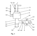
- FIG. 1 a conventional emergency cooling module 2 is shown with an axial fan 2.1, which serves for cooling of serving as a coolant 2.2 water.
- This coolant 2.2 is the emergency cooling module 2 supplied with a flow temperature of about 85 ° C to 95 ° C and cooled in Notkühlmodul 2 to a return temperature of about 75 ° C to 80 ° C.
- the intake air 1 sucked in is predominantly outside air 1.1.
- the emergency cooling module 2 leaving hot air 3 has a temperature of about 30 ° C to 50 ° C and is guided in a channel which branches into two channels; namely in a first channel for guiding a first hot air stream 3.1 and in a second channel for guiding a second hot air stream 3.2.
- the first channel for guiding the first warm air stream 3.1 contains a ventilation flap 3.3 and connects to an adapter 4 which supplies the first warm air stream 3.1 to a dryer 5.
- the second channel for guiding the second hot air stream 3.2 contains a second ventilation flap 3.4 and is led over the roof (exhaust air).
- one is Channel, which serves to supply warm and dry room air 1.2, connected to the emergency cooling module 2;
- This channel contains a third ventilation flap 1.3.
- the dryer 5 is used for low-temperature drying of wet material 5.1, with which the dryer 5 has been charged; The result is a dry material 5.2, which is taken from the dryer 5.
- the temperature range around 40 ° C allows gentle drying of the moist material (5.1).
- the illustrated system performs a bivalent function; namely the emergency cooling of combined heat and power generation and the production of hot air 3 and their use for gentle drying processes.
- the drying process according to the invention is gentle drying, in which neither exhaust emissions nor excessive drying temperatures influence the quality of the dried material 5.2.
- the CHP and the dryer 5 are locally bound to avoid high heat losses; However, the location of the heat exchanger emergency cooling drying system (WNT system) does not necessarily have to be linked to the CHP room. It is sufficient to arrange the emergency cooling module 2 in the vicinity of the dryer 5. Both the cooling process of the coolant 2.2 and the drying process of the moist material 5.1 are controlled via a control system.
- signals of a humidity sensor 5.3 are evaluated for measuring the moisture of the dryer 5 leaving exhaust air; Depending on the moisture 5.2, the evaluation is freely programmable. If the desired degree of dryness is reached, the first ventilation flap 3.3 is closed and the second ventilation flap 3.4 is opened, so that the dryer 5 is deactivated and the dry dry material 5.2 can be removed and the dryer 5 new moist 5.1 can be fed via a sensor-monitored device for feeding , The meanwhile accumulating hot air 3 is discharged as the second hot air stream 3.2 as exhaust air over the roof.
- the dryer 5 is designed as a set, continuous or drum dryer.
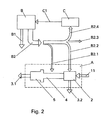
- FIG. 2 shown systematic overview shows a coupled with a combined heat and power plant B heat exchanger emergency cooling dryer system A; contains the heat exchanger emergency cooling dryer system A - as under FIG. 1 The dryer 5, the emergency cooling module 2 and the adapter 4 arranged therebetween are described.
- the heat exchanger emergency cooling dryer system A is supplied with outside air 1.1, which is heated in the emergency cooling module 2 and discharged as heat flow 3.1, 3.2.
- heat B2 In the combined heat and power plant (CHP) B, in addition to the electric current B1, heat B2 is produced, which is referred to as radiant heat B2. 1 the heat exchanger emergency cooling dryer system A and B2.2 as excess heat is supplied directly to the emergency cooling module 2, is used as useful heat B2.3 for space heating and domestic water heating and process heat B2.4 a bioenergy production C is supplied. In the bioenergy production C generated bio-primary energy C1 is the cogeneration unit (CHP) B supplied.
- CHP cogeneration unit
Landscapes
- Engineering & Computer Science (AREA)
- Life Sciences & Earth Sciences (AREA)
- Sustainable Development (AREA)
- Mechanical Engineering (AREA)
- General Engineering & Computer Science (AREA)
- Drying Of Solid Materials (AREA)
- Manufacturing And Processing Devices For Dough (AREA)
Claims (9)
- Procédé de séchage d'une matière humide (5.1) par de l'air chaud (3) dans un séchoir (5), où- de l'air d'amenée (1) traverse au moins temporairement un réchauffeur et est ainsi réchauffé,- après passage par le réchauffeur, l'air chaud (3) généré est divisé- en un premier courant d'air chaud (3.1) régulable au moyen d'un premier clapet d'aération (3.3) et en un deuxième courant d'air chaud (3.2) régulable au moyen d'un deuxième clapet d'aération (3.4),- le premier courant d'air chaud (3.1) est conduit vers le séchoir (5), traverse celui-ci et absorbe alors l'humidité de la matière humide (5.1) disposée dans le séchoir (5) ou est extrait comme air rejeté par le toit,- après passage par le séchoir (5), l'humidité du premier courant d'air chaud (3.1) est mesurée au moyen d'un capteur d'humidité (5.3), et où- les positions du premier clapet d'aération (3.3) et du deuxième clapet d'aération (3.4) sont commandées au moyen d'un système de commande en fonction de l'humidité mesurée par le capteur d'humidité (5.3),caractérisé- en ce que le réchauffeur est un module de refroidissement de secours (2) prévu pour le refroidissement d'un réfrigérant (2.2) d'une centrale de chauffage à distance,- de l'air ambiant (1.2) au moins temporairement sec et chaud de la centrale de chauffage à distance est conduit vers le module de refroidissement de secours (2) et cette amenée est toujours commandée en cours de processus de séchage au moyen d'un troisième clapet d'aération (1.3), et- en ce que le premier courant d'air chaud (3.1) est conduit vers le séchoir (5) lorsque de la chaleur excédentaire est présentée et que de la matière humide se trouve dans le séchoir (5).
- Procédé selon la revendication 1, caractérisé en ce que la température du premier courant d'air chaud (3.1) conduit vers le séchoir (5) est régulée par le système de commande, par commande d'un ventilateur axial (2.1) du module de refroidissement de secours (2), à une valeur comprise entre 30°C et 50°C, et en ce qu'un réchauffeur d'air (6) est activé si la température du premier courant d'air chaud (3.1) tombe sous une température minimale.
- Procédé selon l'une des revendications 1 ou 2, caractérisé en ce que des signaux d'un capteur de pression (2.3) sont saisis et traités par le système de commande dans le circuit du réfrigérant (2.2).
- Dispositif pour l'exécution du procédé selon l'une des revendications 1 à 3, où- un canal pour l'amenée d'air chaud (3) est disposé entre un module de refroidissement de secours (2) prévu pour le refroidissement d'un réfrigérant (2.2) d'une centrale de chauffage à distance, où s'écoule de l'air d'amenée (1), et un séchoir (5),- ledit canal est réalisé avec des branchements, un branchement pour la conduction d'un premier courant d'air chaud (3.1) contenant un premier clapet d'aération (3.3) et étant raccordé au séchoir (5), et un deuxième branchement formant un canal d'extraction d'air pour la conduction d'un deuxième courant d'air chaud (3.2) et contenant un deuxième clapet d'aération (3.4),- un capteur d'humidité (5 .3) est disposé à la sortie du premier courant d'air chaud (3.1) après le séchoir (5),- un système de commande pour la commande du premier clapet d'aération (3.3) et du deuxième clapet d'aération (3.4) en fonction de l'humidité mesurée par le capteur d'humidité (5.3) est prévu, et où- un autre canal pour l'amenée d'air ambiant sec et chaud (1.2), où est prévu un troisième clapet d'aération (1.3), est disposé entre la centrale de chauffage à distance et le module de refroidissement de secours (2).
- Dispositif selon la revendication 4, caractérisé en ce qu'un réchauffeur d'air (6) activable par le système de commande est disposé sur le séchoir (5).
- Dispositif selon la revendication 4 ou 5, caractérisé en ce qu'un capteur de pression (2.3) pour la saisie de la pression et donc de l'écoulement dans le circuit de réfrigérant est disposé dans l'amenée du réfrigérant (2.2).
- Dispositif selon les revendications 4 à 6, caractérisé en ce qu'un autre capteur d'humidité (5.4) est disposé dans le premier courant d'air chaud (3.1) conduit dans le séchoir (5).
- Dispositif selon l'une des revendications 4 à 7, caractérisé en ce que le séchoir (5) est réalisé comme séchoir discontinu, continu ou rotatif, et en ce qu'un dispositif de chargement de matière humide (5.1) à sécher et un dispositif de déchargement de matière séchée (5.2) sont prévus sur le séchoir.
- Dispositif selon l'une des revendications 4 à 8, caractérisé en ce que plusieurs modules de refroidissement de secours (2) sont montés en parallèle et en ce que de l'air chaud (3) est conduit vers le séchoir (5) depuis lesdits modules de refroidissement de secours (2), la capacité de réfrigération de chaque module de refroidissement de secours (2) étant comprise entre 100 kW et 200 kW.
Applications Claiming Priority (2)
| Application Number | Priority Date | Filing Date | Title |
|---|---|---|---|
| DE10225489 | 2002-06-10 | ||
| DE10225489A DE10225489A1 (de) | 2002-06-10 | 2002-06-10 | Verfahren und Vorrichtung zur Trocknung von Feuchtgut mittels Warmluft |
Publications (2)
| Publication Number | Publication Date |
|---|---|
| EP1371925A1 EP1371925A1 (fr) | 2003-12-17 |
| EP1371925B1 true EP1371925B1 (fr) | 2010-05-12 |
Family
ID=29557678
Family Applications (1)
| Application Number | Title | Priority Date | Filing Date |
|---|---|---|---|
| EP03012969A Expired - Lifetime EP1371925B1 (fr) | 2002-06-10 | 2003-06-07 | Procédé et dispositif pour le séchage de matériau humide par de l'air chaud |
Country Status (3)
| Country | Link |
|---|---|
| EP (1) | EP1371925B1 (fr) |
| AT (1) | ATE467805T1 (fr) |
| DE (2) | DE10225489A1 (fr) |
Families Citing this family (1)
| Publication number | Priority date | Publication date | Assignee | Title |
|---|---|---|---|---|
| DE102016109415A1 (de) | 2016-05-23 | 2017-11-23 | Trützschler GmbH + Co KG Textilmaschinenfabrik | Trocknereinrichtung und Trockner für eine textile Warenbahn mit einer verbesserten Einrichtung zur Wärmeeinbringung |
Family Cites Families (10)
| Publication number | Priority date | Publication date | Assignee | Title |
|---|---|---|---|---|
| US2122037A (en) * | 1936-07-27 | 1938-06-28 | Louisville Drying Machinery Co | Utilization of waste gases |
| DE3805690A1 (de) * | 1988-02-24 | 1989-08-31 | Wibau Maschinen Gmbh | Kraft-waerme-kopplung |
| DE4426356A1 (de) * | 1993-07-27 | 1995-02-02 | Waermetechnik Dr Pauli Gmbh | Vorrichtung zum Trocknen von Grünfutter, Spänen, Schnitzeln, zur Wärmeerzeugung, zur Stromerzeugung oder dergleichen mit Wirkungsgradoptimierung |
| DE19617218C2 (de) * | 1995-11-22 | 1997-10-23 | Eder Christian Dipl Betriebsw | Verfahren und Vorrichtung zum Verarbeiten von biologischen Reststoffen, insbesondere Klärschlamm |
| DE19602330C1 (de) * | 1996-01-24 | 1997-06-26 | Meyer Fa Rud Otto | Blockheizkraftwerk sowie Verfahren zu dessen Betrieb |
| DE19654093C2 (de) | 1996-12-23 | 2000-04-13 | Alb Klein Umwelttechnik Gmbh | Verfahren zur Niedertemperaturtrocknung von Feuchtgut und Vorrichtung zur Durchführung des Verfahrens |
| DE19958108A1 (de) | 1999-12-02 | 2001-06-07 | Hochhaus Karl Heinz | Vorrichtung zur Trocknung von Transportgütern mit Hilfe der Abwärmenutzung |
| US6364948B1 (en) * | 2000-03-21 | 2002-04-02 | Mars, Inc. | Coating and drying apparatus |
| DE10030293C2 (de) * | 2000-06-27 | 2002-08-01 | Ludger Kipp | Verfahren zur Verwertung und Entsorgung von Grünschnitt |
| DE10046389A1 (de) * | 2000-09-20 | 2002-04-04 | Farmatic Biotech Energy Ag | Vergärung von Tierkörperabfällen im Biogasfermenter |
-
2002
- 2002-06-10 DE DE10225489A patent/DE10225489A1/de not_active Withdrawn
-
2003
- 2003-06-07 AT AT03012969T patent/ATE467805T1/de active
- 2003-06-07 DE DE50312702T patent/DE50312702D1/de not_active Expired - Lifetime
- 2003-06-07 EP EP03012969A patent/EP1371925B1/fr not_active Expired - Lifetime
Also Published As
| Publication number | Publication date |
|---|---|
| DE10225489A1 (de) | 2003-12-18 |
| EP1371925A1 (fr) | 2003-12-17 |
| ATE467805T1 (de) | 2010-05-15 |
| DE50312702D1 (de) | 2010-06-24 |
Similar Documents
| Publication | Publication Date | Title |
|---|---|---|
| EP3380792B1 (fr) | Centrale d'énergie domestique et procédé pour faire fonctionner une centrale d'énergie domestique | |
| US4499911A (en) | Energy efficient curing and drying system | |
| DE102007003144A1 (de) | Vorrichtung zur Aufbereitung von Reaktionsgasen in Brennstoffzellen | |
| DE4306217A1 (de) | Programmgesteuerter Wäschetrockner mit einem Wärmepumpenkreis | |
| DE102016014643B4 (de) | Durchlauftrockner zum Trocknen eines Gutes mittels Warmluft mit mindestens zwei Sektionen | |
| DE102015209370B3 (de) | Trockner | |
| WO2008089884A1 (fr) | Dispositif de refroidissement en circuit fermé et d'humidification dans des piles à combustible | |
| DE10033052A1 (de) | Verfahen zum Betreiben einer Gasturbinenanlage sowie Gasturbinenanlage zur Durchführung des Verfahrens | |
| DE102010062142A1 (de) | Trocknersystem einer Bedruckstoff be- und/oder verarbeitenden Druckmaschine sowie Verfahren zum Betrieb eines Trockners einer Bedruckstoff be- und/oder verarbeitenden Druckmaschine | |
| EP1371925B1 (fr) | Procédé et dispositif pour le séchage de matériau humide par de l'air chaud | |
| DE102008049034A1 (de) | Ablufttrockner | |
| DE102010062144B4 (de) | Druckmaschine mit mindestens einem einen Heißlufttrockner aufweisenden Trocknersystem sowie Verfahren zum Betreiben eines einen Heißlufttrockner aufweisenden Trocknersystems | |
| EP0098481B1 (fr) | Méthode pour générer de l'énergie électrique dans une centrale combinée à combustion en lit fluidisé | |
| EP3757494B1 (fr) | Système de séchage et procédé de séchage | |
| AT14386U1 (de) | Vortrocknungsvorrichtung für eine trocknungsanlage | |
| DE102007051962A1 (de) | Materialbahntrockneranordnung | |
| DE102010062145B4 (de) | Druckmaschine mit mindestens einem einen Heißlufttrockner aufweisenden Trocknersystem sowie Verfahren zum Betrieb einer Druckmaschine mit mindestens einem Heißlufttrockner | |
| CN216500502U (zh) | 一种涂布机节能加热减排热风的装置 | |
| US4268974A (en) | Hoods for the cylinder drying section of paper making machines and other cylinder drying machines | |
| CN209459336U (zh) | 一种新型排湿烘房的结构 | |
| CN109330009B (zh) | 一种烤烟热泵双动力烤房 | |
| DE102004060495A1 (de) | Verfahren zum kontrollierten Be- und Entlüften sowie kontrollierten Erwärmen und Kühlen eines Gebäudes sowie entsprechende Vorrichtung | |
| DE3729910A1 (de) | Druckaufgeladen betreibbare wirbelschichtfeuerung | |
| CN215337391U (zh) | 一种利用相对湿度多点控制药材烘干的排湿系统 | |
| DE102024109125A1 (de) | Vorrichtung zur Wassererwärmung sowie Verfahren und System zur kombinierten Luft- und Wassererwärmung |
Legal Events
| Date | Code | Title | Description |
|---|---|---|---|
| PUAI | Public reference made under article 153(3) epc to a published international application that has entered the european phase |
Free format text: ORIGINAL CODE: 0009012 |
|
| AK | Designated contracting states |
Kind code of ref document: A1 Designated state(s): AT BE BG CH CY CZ DE DK EE ES FI FR GB GR HU IE IT LI LU MC NL PT RO SE SI SK TR |
|
| AX | Request for extension of the european patent |
Extension state: AL LT LV MK |
|
| 17P | Request for examination filed |
Effective date: 20031128 |
|
| AKX | Designation fees paid |
Designated state(s): AT BE BG CH CY CZ DE DK EE ES FI FR GB GR HU IE IT LI LU MC NL PT RO SE SI SK TR |
|
| GRAP | Despatch of communication of intention to grant a patent |
Free format text: ORIGINAL CODE: EPIDOSNIGR1 |
|
| GRAS | Grant fee paid |
Free format text: ORIGINAL CODE: EPIDOSNIGR3 |
|
| GRAA | (expected) grant |
Free format text: ORIGINAL CODE: 0009210 |
|
| AK | Designated contracting states |
Kind code of ref document: B1 Designated state(s): AT BE BG CH CY CZ DE DK EE ES FI FR GB GR HU IE IT LI LU MC NL PT RO SE SI SK TR |
|
| REG | Reference to a national code |
Ref country code: GB Ref legal event code: FG4D Free format text: NOT ENGLISH |
|
| REG | Reference to a national code |
Ref country code: CH Ref legal event code: EP |
|
| REG | Reference to a national code |
Ref country code: IE Ref legal event code: FG4D Free format text: LANGUAGE OF EP DOCUMENT: GERMAN |
|
| REF | Corresponds to: |
Ref document number: 50312702 Country of ref document: DE Date of ref document: 20100624 Kind code of ref document: P |
|
| REG | Reference to a national code |
Ref country code: NL Ref legal event code: T3 |
|
| PG25 | Lapsed in a contracting state [announced via postgrant information from national office to epo] |
Ref country code: SE Free format text: LAPSE BECAUSE OF FAILURE TO SUBMIT A TRANSLATION OF THE DESCRIPTION OR TO PAY THE FEE WITHIN THE PRESCRIBED TIME-LIMIT Effective date: 20100512 Ref country code: ES Free format text: LAPSE BECAUSE OF FAILURE TO SUBMIT A TRANSLATION OF THE DESCRIPTION OR TO PAY THE FEE WITHIN THE PRESCRIBED TIME-LIMIT Effective date: 20100823 |
|
| PG25 | Lapsed in a contracting state [announced via postgrant information from national office to epo] |
Ref country code: SI Free format text: LAPSE BECAUSE OF FAILURE TO SUBMIT A TRANSLATION OF THE DESCRIPTION OR TO PAY THE FEE WITHIN THE PRESCRIBED TIME-LIMIT Effective date: 20100512 Ref country code: FI Free format text: LAPSE BECAUSE OF FAILURE TO SUBMIT A TRANSLATION OF THE DESCRIPTION OR TO PAY THE FEE WITHIN THE PRESCRIBED TIME-LIMIT Effective date: 20100512 |
|
| REG | Reference to a national code |
Ref country code: IE Ref legal event code: FD4D |
|
| BERE | Be: lapsed |
Owner name: ZEUS ENERGIE- UND UMWELTSYSTEME G.M.B.H. ZWONITZ Effective date: 20100630 |
|
| PG25 | Lapsed in a contracting state [announced via postgrant information from national office to epo] |
Ref country code: GR Free format text: LAPSE BECAUSE OF FAILURE TO SUBMIT A TRANSLATION OF THE DESCRIPTION OR TO PAY THE FEE WITHIN THE PRESCRIBED TIME-LIMIT Effective date: 20100813 Ref country code: CY Free format text: LAPSE BECAUSE OF FAILURE TO SUBMIT A TRANSLATION OF THE DESCRIPTION OR TO PAY THE FEE WITHIN THE PRESCRIBED TIME-LIMIT Effective date: 20100512 |
|
| PG25 | Lapsed in a contracting state [announced via postgrant information from national office to epo] |
Ref country code: IE Free format text: LAPSE BECAUSE OF FAILURE TO SUBMIT A TRANSLATION OF THE DESCRIPTION OR TO PAY THE FEE WITHIN THE PRESCRIBED TIME-LIMIT Effective date: 20100512 Ref country code: MC Free format text: LAPSE BECAUSE OF NON-PAYMENT OF DUE FEES Effective date: 20100630 Ref country code: PT Free format text: LAPSE BECAUSE OF FAILURE TO SUBMIT A TRANSLATION OF THE DESCRIPTION OR TO PAY THE FEE WITHIN THE PRESCRIBED TIME-LIMIT Effective date: 20100913 Ref country code: DK Free format text: LAPSE BECAUSE OF FAILURE TO SUBMIT A TRANSLATION OF THE DESCRIPTION OR TO PAY THE FEE WITHIN THE PRESCRIBED TIME-LIMIT Effective date: 20100512 Ref country code: EE Free format text: LAPSE BECAUSE OF FAILURE TO SUBMIT A TRANSLATION OF THE DESCRIPTION OR TO PAY THE FEE WITHIN THE PRESCRIBED TIME-LIMIT Effective date: 20100512 |
|
| PG25 | Lapsed in a contracting state [announced via postgrant information from national office to epo] |
Ref country code: SK Free format text: LAPSE BECAUSE OF FAILURE TO SUBMIT A TRANSLATION OF THE DESCRIPTION OR TO PAY THE FEE WITHIN THE PRESCRIBED TIME-LIMIT Effective date: 20100512 Ref country code: RO Free format text: LAPSE BECAUSE OF FAILURE TO SUBMIT A TRANSLATION OF THE DESCRIPTION OR TO PAY THE FEE WITHIN THE PRESCRIBED TIME-LIMIT Effective date: 20100512 Ref country code: CZ Free format text: LAPSE BECAUSE OF FAILURE TO SUBMIT A TRANSLATION OF THE DESCRIPTION OR TO PAY THE FEE WITHIN THE PRESCRIBED TIME-LIMIT Effective date: 20100512 |
|
| PLBE | No opposition filed within time limit |
Free format text: ORIGINAL CODE: 0009261 |
|
| STAA | Information on the status of an ep patent application or granted ep patent |
Free format text: STATUS: NO OPPOSITION FILED WITHIN TIME LIMIT |
|
| 26N | No opposition filed |
Effective date: 20110215 |
|
| REG | Reference to a national code |
Ref country code: DE Ref legal event code: R097 Ref document number: 50312702 Country of ref document: DE Effective date: 20110214 |
|
| PG25 | Lapsed in a contracting state [announced via postgrant information from national office to epo] |
Ref country code: BE Free format text: LAPSE BECAUSE OF NON-PAYMENT OF DUE FEES Effective date: 20100630 |
|
| PGFP | Annual fee paid to national office [announced via postgrant information from national office to epo] |
Ref country code: FR Payment date: 20110630 Year of fee payment: 9 Ref country code: CH Payment date: 20110623 Year of fee payment: 9 |
|
| PGFP | Annual fee paid to national office [announced via postgrant information from national office to epo] |
Ref country code: NL Payment date: 20110623 Year of fee payment: 9 Ref country code: AT Payment date: 20110620 Year of fee payment: 9 Ref country code: GB Payment date: 20110621 Year of fee payment: 9 |
|
| PGFP | Annual fee paid to national office [announced via postgrant information from national office to epo] |
Ref country code: DE Payment date: 20110427 Year of fee payment: 9 |
|
| PGFP | Annual fee paid to national office [announced via postgrant information from national office to epo] |
Ref country code: IT Payment date: 20110627 Year of fee payment: 9 |
|
| PG25 | Lapsed in a contracting state [announced via postgrant information from national office to epo] |
Ref country code: HU Free format text: LAPSE BECAUSE OF FAILURE TO SUBMIT A TRANSLATION OF THE DESCRIPTION OR TO PAY THE FEE WITHIN THE PRESCRIBED TIME-LIMIT Effective date: 20101113 Ref country code: BG Free format text: LAPSE BECAUSE OF FAILURE TO SUBMIT A TRANSLATION OF THE DESCRIPTION OR TO PAY THE FEE WITHIN THE PRESCRIBED TIME-LIMIT Effective date: 20100512 Ref country code: LU Free format text: LAPSE BECAUSE OF NON-PAYMENT OF DUE FEES Effective date: 20100607 |
|
| PG25 | Lapsed in a contracting state [announced via postgrant information from national office to epo] |
Ref country code: TR Free format text: LAPSE BECAUSE OF FAILURE TO SUBMIT A TRANSLATION OF THE DESCRIPTION OR TO PAY THE FEE WITHIN THE PRESCRIBED TIME-LIMIT Effective date: 20100512 |
|
| REG | Reference to a national code |
Ref country code: NL Ref legal event code: V1 Effective date: 20130101 |
|
| REG | Reference to a national code |
Ref country code: CH Ref legal event code: PL |
|
| REG | Reference to a national code |
Ref country code: CH Ref legal event code: PL Ref country code: AT Ref legal event code: MM01 Ref document number: 467805 Country of ref document: AT Kind code of ref document: T Effective date: 20120607 |
|
| GBPC | Gb: european patent ceased through non-payment of renewal fee |
Effective date: 20120607 |
|
| PG25 | Lapsed in a contracting state [announced via postgrant information from national office to epo] |
Ref country code: IT Free format text: LAPSE BECAUSE OF NON-PAYMENT OF DUE FEES Effective date: 20120607 |
|
| REG | Reference to a national code |
Ref country code: FR Ref legal event code: ST Effective date: 20130228 |
|
| PG25 | Lapsed in a contracting state [announced via postgrant information from national office to epo] |
Ref country code: FR Free format text: LAPSE BECAUSE OF NON-PAYMENT OF DUE FEES Effective date: 20120702 Ref country code: CH Free format text: LAPSE BECAUSE OF NON-PAYMENT OF DUE FEES Effective date: 20120630 Ref country code: NL Free format text: LAPSE BECAUSE OF NON-PAYMENT OF DUE FEES Effective date: 20130101 Ref country code: LI Free format text: LAPSE BECAUSE OF NON-PAYMENT OF DUE FEES Effective date: 20120630 Ref country code: GB Free format text: LAPSE BECAUSE OF NON-PAYMENT OF DUE FEES Effective date: 20120607 Ref country code: DE Free format text: LAPSE BECAUSE OF NON-PAYMENT OF DUE FEES Effective date: 20130101 |
|
| REG | Reference to a national code |
Ref country code: DE Ref legal event code: R119 Ref document number: 50312702 Country of ref document: DE Effective date: 20130101 |
|
| PG25 | Lapsed in a contracting state [announced via postgrant information from national office to epo] |
Ref country code: AT Free format text: LAPSE BECAUSE OF NON-PAYMENT OF DUE FEES Effective date: 20120607 |
|
| PG25 | Lapsed in a contracting state [announced via postgrant information from national office to epo] |
Ref country code: BG Free format text: LAPSE BECAUSE OF FAILURE TO SUBMIT A TRANSLATION OF THE DESCRIPTION OR TO PAY THE FEE WITHIN THE PRESCRIBED TIME-LIMIT Effective date: 20100812 |