EP1372012B1 - Dispositif optique pour l'observation d'un échantillon ou d'un objet - Google Patents
Dispositif optique pour l'observation d'un échantillon ou d'un objet Download PDFInfo
- Publication number
- EP1372012B1 EP1372012B1 EP03007650A EP03007650A EP1372012B1 EP 1372012 B1 EP1372012 B1 EP 1372012B1 EP 03007650 A EP03007650 A EP 03007650A EP 03007650 A EP03007650 A EP 03007650A EP 1372012 B1 EP1372012 B1 EP 1372012B1
- Authority
- EP
- European Patent Office
- Prior art keywords
- illumination
- optical arrangement
- arrangement according
- splitter
- mirror
- Prior art date
- Legal status (The legal status is an assumption and is not a legal conclusion. Google has not performed a legal analysis and makes no representation as to the accuracy of the status listed.)
- Expired - Lifetime
Links
- 230000003287 optical effect Effects 0.000 title claims abstract description 58
- 238000005286 illumination Methods 0.000 claims abstract description 87
- 238000011156 evaluation Methods 0.000 claims abstract description 21
- 238000001514 detection method Methods 0.000 claims description 53
- 210000001747 pupil Anatomy 0.000 claims description 36
- 230000005855 radiation Effects 0.000 claims description 25
- 230000008859 change Effects 0.000 claims description 23
- 230000003044 adaptive effect Effects 0.000 claims description 12
- 101000805601 Crotalus atrox Zinc metalloproteinase-disintegrin-like atrolysin-A Proteins 0.000 claims description 3
- 230000000712 assembly Effects 0.000 claims description 2
- 238000000429 assembly Methods 0.000 claims description 2
- 230000006978 adaptation Effects 0.000 claims 1
- 238000000034 method Methods 0.000 claims 1
- 238000011144 upstream manufacturing Methods 0.000 claims 1
- 230000023077 detection of light stimulus Effects 0.000 abstract 1
- 239000000523 sample Substances 0.000 description 33
- 238000003384 imaging method Methods 0.000 description 7
- 230000005540 biological transmission Effects 0.000 description 6
- 230000004075 alteration Effects 0.000 description 5
- 238000012937 correction Methods 0.000 description 5
- 229910000831 Steel Inorganic materials 0.000 description 2
- 238000001914 filtration Methods 0.000 description 2
- 238000001917 fluorescence detection Methods 0.000 description 2
- 230000004044 response Effects 0.000 description 2
- 239000010959 steel Substances 0.000 description 2
- 201000009310 astigmatism Diseases 0.000 description 1
- 238000004891 communication Methods 0.000 description 1
- 230000008878 coupling Effects 0.000 description 1
- 238000010168 coupling process Methods 0.000 description 1
- 238000005859 coupling reaction Methods 0.000 description 1
- 238000011161 development Methods 0.000 description 1
- 230000000694 effects Effects 0.000 description 1
- 230000006872 improvement Effects 0.000 description 1
- 230000003993 interaction Effects 0.000 description 1
- 238000012544 monitoring process Methods 0.000 description 1
- 238000005457 optimization Methods 0.000 description 1
- 238000004621 scanning probe microscopy Methods 0.000 description 1
- 238000004904 shortening Methods 0.000 description 1
Images


Classifications
-
- G—PHYSICS
- G02—OPTICS
- G02B—OPTICAL ELEMENTS, SYSTEMS OR APPARATUS
- G02B21/00—Microscopes
- G02B21/0004—Microscopes specially adapted for specific applications
- G02B21/002—Scanning microscopes
- G02B21/0024—Confocal scanning microscopes (CSOMs) or confocal "macroscopes"; Accessories which are not restricted to use with CSOMs, e.g. sample holders
- G02B21/0036—Scanning details, e.g. scanning stages
- G02B21/0048—Scanning details, e.g. scanning stages scanning mirrors, e.g. rotating or galvanomirrors, MEMS mirrors
-
- G—PHYSICS
- G02—OPTICS
- G02B—OPTICAL ELEMENTS, SYSTEMS OR APPARATUS
- G02B21/00—Microscopes
- G02B21/0004—Microscopes specially adapted for specific applications
- G02B21/002—Scanning microscopes
- G02B21/0024—Confocal scanning microscopes (CSOMs) or confocal "macroscopes"; Accessories which are not restricted to use with CSOMs, e.g. sample holders
- G02B21/0032—Optical details of illumination, e.g. light-sources, pinholes, beam splitters, slits, fibers
Definitions
- the invention relates to an optical arrangement for obtaining information from a sample or an observation object, comprising a light source for illuminating the sample or the observation object, and a receiving device for the light emitted by the sample or by the observation object.
- optical observation devices such as microscopes
- variable optics known from the prior art for adapting a beam path to an objective are designed, for example, as simple telescopes or cylinder optics, and as a rule have reflective and / or refractive optical elements.
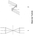
- Refractive optical elements are used, as shown for example in the figure "prior art 1", so this requires a relatively large amount of space, which is due to the sum of the focal lengths of the individual lenses. Furthermore, when using refractive optical elements measures for Correction of chromatic aberrations when using polychromatic light sources, otherwise the imaging properties are not the same for all wavelengths.
- EP750891 describes a laser micromanipulator for surgical applications with autofocus with a beam splitter having a splitter surface with a transmissive and a reflective region.
- US6078420 describes a laser scanning system with a coupling of the focused laser light through a hole mirror. The need for optimizing image quality exists, in particular with regard to laser scanning microscopy, which has recently experienced a development spurt. In this subject matter, the invention set forth below refers.
- the concave mirrors are each positioned in a pupil plane of the illumination or detection beam path.
- the beam splitters can be arranged in an intermediate image plane or pupil plane of the illumination or detection beam path.
- adjusting devices for varying the focal length of the concave mirror and / or for changing the distance between the respective beam splitter and the associated concave mirror are provided.
- a variable beam expansion can be carried out in a simple manner, with the variation of the focal length of the concave mirror and the change in the distance between Beam splitter and concave mirror and the change of the focal distance can be made in a likewise simple way a beam expansion with correction of the focus position.
- the detection device is connected via an evaluation device with the adjusting devices, and the evaluation device generates in response to the detector signal actuating signals that are used to vary the focal length of the concave mirror and / or to change the distance between the respective beam splitter and the associated concave mirror ,
- the information about the radiation intensity received by the detection device is converted into electronic control signals by means of the evaluation device and used to generate corresponding manipulated variables so that, if necessary, the efficiency of the device is substantially increased by varying the beam expansion or variation of the beam expansion while simultaneously correcting the focus position. by adapting the transmission to the focus volume. If only the focus position is changed with the described means, it is also possible, for example, to carry out a focus scan.
- the concave mirror arranged in the detection beam path focuses the detection light onto the beam splitter, so that the detection light in the region of the focus passes through the transmissive region and subsequently reaches the detection device.
- the transmissive area acts as a confocal aperture in the detection beam path.
- the focal length By varying the focal length, it is possible to adjust the size of the confocal aperture (pinhole size) or the spot size at the location of the sample and thus to increase the resolution of the laser scanning microscope.
- a spherical concave mirror is provided in the illumination beam path and / or in the detection beam path, which is arranged together with further spherical concave mirrors of different focal lengths on a communicating with the evaluation changer, wherein by rotation of the change wheel to a rotation angle of the evaluation is specified, each a spherical. Concave mirror selected focal length is placed in the illumination beam path.
- an adaptive spherical concave mirror instead of a plurality of arranged on the change wheel spherical concave mirror and an adaptive spherical concave mirror may be provided which is equipped with an adjustable, the focal length varying mirror surface and is in communication with the evaluation, in each case by means of a control signal generated in the evaluation set a selected focal length becomes.
- the transmissive region of the beam splitter does not act as a confocal aperture or as a spatial filter and is advantageously designed as an opening with a diameter of at least 5 Airy.
- the transmissive region acts as a spatial filter
- the diameter of the transmissive region must be adapted accordingly.
- the splitter surface is inclined by 45 ° to the incident illumination or detection light, and it has in its center a circular or elliptical, the transmissive region forming opening which is surrounded by the reflective surface formed as a mirror surface.
- the transmissive region is designed as an elliptical opening, then the 45 ° inclination of the divider surface against the incident illumination or detection light advantageously results in a seemingly circular passage opening.
- Each beam splitter can in the direction of the initially unfocused striking its splitter surface lighting or
- Detection light a detector for receiving the not directed from the reflective region to the concave mirror, but passing through the transmissive region radiation component to be arranged downstream.
- the signal obtained with this detector can be used advantageously for monitoring the average power of the respective radiation.
- the detector may be designed as a monitor diode.
- T the transmission
- a HT the area of the transmissive area
- r HT the radius of the transmissive area
- r pupille the radius. of the pupil
- a lens or a lens system for collimating is advantageously provided in the beam path of passing through the transmissive region and directed to the sample illumination light and further in the beam path in front of the sample, a scanning optics and a tube lens, which finally follows the lens.
- a diffraction-limited spot is generated, which is moved laterally over the sample by the scanning device, which is located in or in the vicinity of a pupil of the optical arrangement, thereby scanning the sample.
- the light emitted by the sample emerges as a detection beam path in the reverse direction through the objective, the tube lens, the scanning optics and the scanning device, is advantageously separated by means of a dichroic beam splitter from the illumination beam path and passes through a Pinholeoptik and a confocal aperture to the detection device.
- a wavelength filter can additionally be pivoted into the detection beam path, which serves to suppress the illumination light, so that the light received by the detection device is not influenced by the illumination light.
- a spherical concave mirror is provided in the illumination and / or in the detection beam path, which focuses the illuminating light punctiform on the splitter surface, where it passes through the designed as a circular or elliptical opening transmissive region, and it is the splitter surface in the direction of passage arranged downstream of a further spherical concave mirror, which is incident on the passing illumination light and which reflects this collimated to the splitter surface, where it is deflected by a rear-side mirroring of the splitter surface in the direction of the sample or on the detection device.
- a pupil r pupil 2 - r HT 2 r pupil 2 where R should be greater than 99%.
- a pupil is the effective pupil cross section
- a HT is the area of the transmissive area
- r is the pupil radius
- r HT is the radius of the transmissive area.
- one or more of the concave mirrors may be assigned refractive optical elements which cause a shortening of the focal length of the respective concave mirror.
- refractive optical elements For example, lenses, imaging mirrors or the like come into consideration.
- the invention also includes embodiments in which the positions of the transmissive and reflective regions on the splitter surface are interchanged, d. H. Both the transmissive and the reflective region may be located either in the center of the splitter surface or on its periphery.
- the pupil plane is identical to the reflector surface of the scanning device of the microscope.
- the arrangement of a dichroic beam splitter for the purpose of branching off the detection light coming from the sample from the illumination beam path in all described embodiments is also advantageous.
- Information about the radiation intensity is available at the outputs of the detection devices. This information is compared in the evaluation with information stored there, and from the difference thus determined, control signals are generated, which are used to change the focal length of the adaptive mirror, the Derhung the change gears or the change in the distances between a concave mirror and the associated splitter surface can be used.
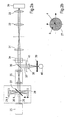
- the illumination light 2 emitted by a light source 1 strikes the splitter surface 3 of an optical beam splitter.
- Out 1b shows It can be seen that the splitter surface 3 has a transmissive region 4 formed as an opening, which is surrounded by a reflective region 5.
- the transmissive region 3 is designed, for example, as a circular or elliptically shaped opening, the reflective region 5 as a mirror surface.
- the splitter surface 3 is inclined at 45 ° to the incident illumination light 2. It is thereby achieved that a radiation portion 2.1 of the illumination light is deflected by the reflective area 5 in the direction of a spherical concave mirror 6, which is located in a pupil plane of the illustrated optical arrangement.
- the spherical concave mirror 6 focuses the radiation component 2.1 back into the transmissive region 4, which is positioned in an intermediate image plane and thus acts as a confocal diaphragm in the illumination beam path.
- the optical resolution of the arrangement can be influenced or specified.
- the transmissive region 4 has an elliptical shape, this assumes an apparent circular shape due to the 45 ° inclination in the direction of projection of the radiation coming from the concave mirror 6.
- the illumination light focused through the transmissive region 4 is subsequently collimated by means of a lens 7.
- a scanning optics 8, a tube lens 9 and the microscope objective 10 generate a spot in the sample 11, which is moved in the lateral direction for the purpose of punctiform scanning of the sample 11 with the aid of the scanning device 12.
- the tube lens 9, the scanning optics 8 and the scanning device 12 On the way back through the microscope objective 10, the tube lens 9, the scanning optics 8 and the scanning device 12, the detection light radiated from the sample 11 and the image information passes to a dichroic beam splitter 13 which decouples the detection beam path 14 from the illumination beam path and onto the splitter surface 15 directed another beam splitter.
- the splitter surface 15 is similar in geometry to the splitter surface 3 (see. 1b shows and also inclined at 45 °.
- a predominant radiation fraction 14.1 is directed in the direction of a spherical concave mirror 16.
- the concave mirror 16 focuses the radiation fraction 14.1 back into the transmissive region 4 of the splitter surface 15, after which this radiation fraction 14.1 of the detection light strikes a detector 17.
- the intensity of the detection light is measured and passed a corresponding information to an evaluation, which is not shown in the drawing.
- the evaluation device is connected to drives for change wheels 18 and 19 in conjunction, on which, in addition to the spherical concave mirrors 6 and 16, more spherical concave mirrors, the number depending on the configuration of the inventive arrangement may be different. For the sake of clarity, only one concave mirror 6.1 and one concave mirror 16.1 are shown by these concave mirrors.
- control signals are generated in the evaluation device, which cause the rotation of the change wheels 18 and / or 19 by predetermined rotation angle, whereby respective concave mirrors of different focal lengths in the radiation fraction 2.1 of the illumination light or in the radiation fraction 14.1 of the detection light.
- the splitter surface 3 in the direction of the incident illumination light 2 a detector 17.1, for example, a monitor diode, downstream, which serves to monitor the average power of the illumination light.
- the size of the decoupled light results from the already mentioned above function for T.
- control signals for changing the geometry of the concave mirror surface are generated for this purpose as a function of the detection signals.
- FIG. 2a shows an embodiment of the arrangement according to the invention, in which a variable optics is provided only in the illumination beam path.
- the coming from a light source 25 collimated illumination light 26 is first directed to the splitter surface 27 of a beam splitter, which (as in the previous embodiment and again in 2b shown) has a transmissive region 4 and a reflective region 5.
- the splitter surface 27 is inclined at 45 ° to the incident illuminating light 26 so that a radiation portion 26.1 of the reflective region 5 is first directed to a concave mirror 28 and is focused by its mirror surface back into the transmissive region 4 of the splitter surface 27.
- the light focused through the transmissive region 4 reaches a subsequently arranged spherical concave mirror 29, which is located in a pupil plane of the illumination beam path.
- the concave mirror 29 and the splitter surface 27 are arranged to each other so that the transmissive region 4 is located in the focal point of the concave mirror 29.
- the transmissive region 4 is positioned in an intermediate image plane of the microscope arrangement, so that it can act as a confocal aperture in the illumination beam path.
- the transmissive region 4 is formed as a circular, but preferably as an elliptical opening.
- the concave mirror 29 reflects the radiation fraction 26.1 collimated back to the splitter surface 27, which is also where its incident from the concave mirror 29 collimated illumination light, is mirrored, so that the radiation fraction 26.1 is now deflected in the direction of a sample 30 on its back.
- a diffraction-limited spot is also generated here by means of a scanning optical system 31, a tube lens 32 and the microscope objective 33, which spot is moved over the sample 30 in the lateral direction with the aid of a scanning device 34.
- the scanning device 34 is located in or near a pupil of the microscope arrangement.
- a relay optics 35 is provided in the beam path, which serves to generate a pupil at the location of the concave mirror 29.
- the light emitted by the sample passes through the microscope objective 33, the tube lens 32, the scanning optics 31 and the scanning device 34 onto a dichroic beam splitter 36 which decouples a detection beam path 37.
- the detection beam path 37 passes in the following via a Pinholeoptik 38 and a confocal aperture 39 on a detector 40th
- a swing-wavelength filter 41 is provided, the z. B. in a fluorescence detection for suppressing portions of the illumination light is used.
- the output signal of the detector 40 is applied to an evaluation device, not shown graphically, which serves to evaluate the intensity of the detection light and generates therefrom control signals, which are used to correct the focal distance of the concave mirror 28 and / or the concave mirror 29.
- adjusting devices can either be designed so that the distances between the concave mirrors 28, 29 are changed to the transmissive region 4 by an amount corresponding to a control variable obtained from the detection signal, or the concave mirror 28 and / or the concave mirror 29 as formed adaptive mirror, in which the curvature of the concave mirror surface can be changed by adjusting elements, so that with the change in the geometry of the concave mirror surface of the focal point is varied.
- the ratio of the area of the transmissive area to the area of the reflective area is R> 99%, which means efficient beam splitting. This efficiency is independent of the wavelength used.
- the radius for the reflective area is about 5 mm, and the transmissive area has a radius of less than 0.25 mm.
- the adjustment of the mirror surface can be used to correct aberrations, for example aberrations.
- the two concave mirrors 28, 29 form in their interaction a telescope, with which the beam expansion can be varied.
- the optical resolution for example, due to overexposure of the objective pupil
- the optical resolution for example, to intentionally worsen the optical resolution by underfilling the objective pupil.
- the illumination beam path in the objective pupil can be slightly focused or defocused.
- the axial position of the focus in the sample 30 can be varied (focus scanning).
- the adjustment of the mirror surface additionally achieves a correction of the aberrations in the illumination beam path which are caused by the optical assemblies or the sample 30 to be examined.
- transmissive element for. B. to replace a lens that focuses the illumination light in the transmissive region 4 of the splitter surface 27.
- This transmissive element must then be positioned between the illumination source 25 and the splitter surface 27.
- In 3a is the telescope formed from the concave mirrors 28 and 29 shown in detail.
- the illumination beam path 26 which strikes the splitter surface 27 and is directed there from the reflective region 5 to a predominant radiation fraction 26.1 on the concave mirror 28. From this, the illumination light is reflected back to the transmissive region 4, passes through this on the concave mirror 29, is reflected back from the mirror surface itself, reaches the mirrored back of the splitter surface 27 and is deflected from there in the direction of the sample 30 (see , Fig.2 ).
- the concave mirror 28 as a spherical concave mirror and the transmissive region 4 as a circular opening (see. 3b ), whereby a spot can be generated and a point-scanning device can be operated.
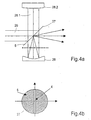
- the in 4a and 4b may be provided as a concave mirror 28, a cylindrical concave mirror and the transmissive region 4 may be formed as a gap-shaped opening. This arrangement serves to form a linear illumination for scanning the sample 30.
- the illumination light 26 again reaches the reflective region 5 of the splitter surface 27 and is directed from there in the direction of the cylindrical concave mirror 28 in this case, which reflects the radiation fraction 26.1 of the illumination light in only one coordinate to the splitter surface 27 thrown back.
- the slit-shaped transmissive region 4 which in 4b can be seen, and the coordinate in which the illumination light is directed to the splitter surface 27, rectified, so that the illumination light is focused through the slit-shaped transmissive region 4 through and hits the downstream spherical concave mirror 29.
- the spherical concave mirror 29 reflects the illumination light back into itself, wherein the line-shaped focused illumination light is rotated by 90 ° to the back mirrored splitter surface 27 and is deflected by this in the direction of the sample 30. Again, only the portion of the illuminating radiation falling on the transmissive area is lost.
- FIG. 5 Another embodiment of the second embodiment is in Figure 5 shown. This refers to the Figure 5 to the generation of a diffraction limited spot for point scanning.
- Figure 6 refers to the generation of line illumination for line scan scanning of the sample 30.
- Figure 5 shows the pair of concave mirrors 28, 29 and the splitter surface 27 from 4a looking towards the on the splitter surface 27 illuminating light 26.
- the splitter surface 27 appears due to its 45 ° inclination from this perspective with an elliptical outline.
- the splitter surface 27 is coupled to a device, not shown in the drawing, for its rotation about the optical axis. If the splitter surface 27 is rotated to a position as shown by the dotted line, then the incident on the reflective region 5 illumination light 26 as already described 2a and 3a described deflected toward the spherical concave mirror 28.1, focussed by this through the transmissive region 4, hits after passage through the transmissive region 4 on the concave mirror 29, is reflected by this collimated again in the direction of the splitter surface 27 and deflected from the mirrored back of the splitter surface 27 to the sample (into the plane of the drawing).
- the two concave mirrors 28.1, 29 act together as a telescope, with which the beam cross-section is affected, either by changing the focal length of one or both of the concave mirrors 28.1, 29, if they are designed as adaptive mirror, or by change their distances to the transmittive area 4.
- the illumination light 26 still hits the reflective region 5 of the splitter surface 27, but is now no longer directed to the concave mirror 28.1, but to the concave mirror 28.11 and from this through the transmissive region 4 focussed through, hits the concave mirror 29.1, is reflected by this collimated on the mirrored back of the splitter surface 27 and deflected there in the direction of the sample 30 (into the plane).
- this embodiment of the invention is not limited to the two illustrated concave mirror pairs 28/29 and 28.11 / 29.1, but it can still be provided more pairs of concave mirrors, which would result in four pairs, for example, a rotation angle for the splitter surface 27 of 45 ° to the Reflection direction to align each with one of the four concave mirror pairs.
- Figure 6 shows the mutatis mutandis same arrangement, but with a slit-shaped transmissive region 4 for generating a linear illumination on the sample 30.
- the operation corresponds in a figurative sense of the just-shown.
- the arrangement according to the invention it is advantageous and easily possible to adapt the steel cross-section in the illumination beam path to the objective pupil and thus to optimize the optical resolution of the entire arrangement.
- the transmission efficiency in the objective can be optimized by adapting the beam cross section in the illumination beam path. It is also possible to change the beam cross section in the illumination beam path with the aim of adjusting the focus volume.
- the length of the illumination line can be adjusted by varying the imaging scale in the illumination beam path.
- the optical section thickness With the change in magnification in the observation beam path, it is also possible to adjust the optical section thickness.
- detector signals are used to generate actuating signals for adjusting devices, so as to automatically influence the beam widening or the focus position.
- detector signals are used to generate actuating signals for adjusting devices, so as to automatically influence the beam widening or the focus position.
- alternative embodiments to dispense with the evaluation device, on adjusting devices and thus on the automatic control, and instead to provide, for example, by manually rotating the exchange wheels concave mirror of different focal lengths in the beam path or by manually moving the concave mirror or beam splitter to change the focal distances so that similar results are achieved.
Landscapes
- Physics & Mathematics (AREA)
- Chemical & Material Sciences (AREA)
- Analytical Chemistry (AREA)
- General Physics & Mathematics (AREA)
- Optics & Photonics (AREA)
- Microscoopes, Condenser (AREA)
- Investigating Or Analysing Materials By Optical Means (AREA)
- Sampling And Sample Adjustment (AREA)
Claims (18)
- Système optique destiné à obtenir des informations concernant un échantillon ou un objet observé et présentant
une source de lumière (1) qui éclaire l'échantillon ou l'objet à observer (11) et un dispositif de réception de la lumière émise par l'échantillon ou par l'objet observé,
au moins un diviseur de faisceau qui présente une surface (3, 27) de diviseur dotée d'une partie transmissive (4) et d'une partie réflexive (5) étant prévu,
un dispositif de balayage (12, 34) qui dévie latéralement la lumière d'éclairage (2, 26) étant utilisé et la partie réflexive (5) de la surface du diviseur étant utilisée pour réfléchir sur un premier miroir creux sphérique (6, 28.1) la lumière d'éclairage collimatée,
la lumière d'éclairage étant concentrée par le premier miroir creux sphérique sur la partie transmissive (4) et traversant cette dernière, caractérisé en ce que
une lentille ou un système (7) de lentilles sont utilisés en amont du dispositif de balayage pour collimater la lumière d'éclairage dans le parcours des rayons de la lumière d'éclairage qui traverse la partie transmissive (4) en direction de l'échantillon ou
en ce que la lumière est concentrée par le premier miroir creux sphérique (6, 28.1) sur la partie transmissive, traverse cette dernière et aboutit sur un deuxième miroir creux sphérique (29) pour y être collimatée, est collimatée par le deuxième miroir creux sphérique (29), est dirigée sur la surface (3, 27) du diviseur et est déviée par sa partie réflexive en direction de l'échantillon par l'intermédiaire du dispositif de balayage,
en ce que la focalisation est influencée par la géométrie de la surface réfléchissante du premier et/ou du deuxième miroir creux sphérique et par la distance entre le miroir creux et la surface (3, 27) du diviseur, un élargissement sélectionné du faisceau est prédéterminé et/ou le front d'onde de la lumière est manipulé dans le but d'obtenir une adaptation optimale de la lumière aux propriétés des autres composants optiques et/ou aux propriétés optiques de l'échantillon ou de l'objet observé, en utilisant des dispositifs (18, 19) de réglage qui font varier la distance focale du miroir creux et/ou qui modifient la distance entre le diviseur de faisceau concerné et le miroir creux associé. - Système optique selon la revendication 1, caractérisé en ce que les miroirs creux (6, 28.1) sont tous utilisés dans un plan de pupille du parcours du faisceau d'éclairage ou du faisceau de détection.
- Système optique selon la revendication 1, caractérisé en ce que les diviseurs de faisceau sont placés chacun dans un plan d'image intermédiaire ou dans le plan de pupille du parcours du faisceau d'éclairage ou du faisceau de détection.
- Système optique selon la revendication 1, caractérisé en ce que les dispositifs de réglage sont reliés par l'intermédiaire d'un dispositif d'évaluation à un dispositif de détection (17) et en ce qu'en fonction du signal du détecteur, le dispositif d'évaluation génère des signaux de réglage qui servent à modifier la distance focale du miroir creux et/ou à modifier la distance entre le diviseur de faisceau concerné et le miroir creux associé.
- Système optique selon l'une des revendications précédentes, caractérisé en ce qu'un miroir creux sphérique (6, 16) est utilisé comme premier miroir creux dans le parcours du faisceau d'éclairage et/ou dans le parcours du faisceau de détection et
est disposé avec d'autres miroirs creux sphériques (6.1, 16.1) de distance focale différente sur une roue d'échange (18, 19), une rotation de la roue d'échange (18, 19) plaçant un miroir creux sphérique (6, 6.1, 16, 16.1) de distance focale sélectionnée dans le parcours (2.1, 14.1) du faisceau d'éclairage ou du faisceau de détection, ou
est configuré avec une surface réfléchissante de distance focale variable, le déplacement déterminant la distance focale sélectionnée. - Système optique selon la revendication 5, caractérisé en ce que les surfaces de diviseur (3, 15) sont inclinées de 45° par rapport à la lumière incidente d'éclairage ou de détection (2, 14) et présente en son centre une ouverture circulaire, de préférence elliptique, qui forme une partie transmissive (4) et qui agit comme filtre spatial pour le parcours du faisceau d'éclairage ou du faisceau de détection.
- Système optique selon l'une des revendications précédentes, caractérisé en ce qu'un détecteur (17.1) est prévu pour recevoir la partie (2, 14) du faisceau qui n'est pas orientée entre la partie réfléchissante (5) et le miroir creux mais qui traverse la partie transmissive (5).
- Système optique selon l'une des revendications précédentes, caractérisé en ce qu'un dispositif optique de collimation, de préférence une lentille (7) ou un système de lentilles, est disposé en aval du diviseur de faisceau dans le parcours du faisceau d'éclairage.
- Système optique selon l'une des revendications 1 à 4, caractérisé en ce que- un miroir creux sphérique (28.1) qui focalise en un point la lumière d'éclairage (26.1) sur la surface (27) du diviseur est utilisé comme premier miroir creux dans le parcours du faisceau d'éclairage ou dans le parcours du faisceau de détection,- en ce que la surface (27) du diviseur est inclinée de 45° par rapport à la lumière d'éclairage (26, 26.1) incidente et présente en son centre une ouverture circulaire ou elliptique qui forme la partie transmissive (4) et que traverse la lumière d'éclairage (26.1) et- en ce qu'un autre miroir creux sphérique (29) servant de deuxième miroir creux est disposé en aval de la surface (27) du diviseur dans la direction de traversée, collimate la lumière d'éclairage (26.1) et la renvoie par réflexion sur la surface (27) du diviseur où la surface (27) du diviseur la dévie par rétroréflexion en direction de l'échantillon (30) ou du dispositif de détection.
- Système optique selon la revendication 9, caractérisé en ce que le rapport entre la surface de la partie transmissive (4) et la surface de la partie réflexive (5) satisfait la condition

dans laquelle Apupille représente la section transversale efficace de pupille, AHT la surface de la partie transmissive (4), rpupille le rayon de pupille et rHT le rayon de la partie transmissive (4), R étant supérieur à 99 %, le rayon de la partie réflexive (5) étant d'environ 5 mm et le rayon de la partie transmissive (4) étant inférieur à 0,25 mm. - Système optique selon l'une des revendications 9 à 10, caractérisé en ce que d'autres miroirs creux (28.11/29.1, 28.21/29.1) situés face à face par paires des deux côtés de la surface de diviseur (27) sont prévus,- en ce que les distances focales des miroirs creux (28.11/29.1, 28.21/29.1) sont différentes d'une paire à l'autre,- en ce que chacune des paires présente un axe optique commun- en ce que les axes optiques des paires sont situés dans le plan XY et sont tournés mutuellement d'un angle α autour de l'axe Z et- en ce que la surface (27) du diviseur est montée à rotation autour de l'axe Z et est couplée à un entraînement qui communique avec le dispositif d'évaluation et- en ce que la surface du diviseur étant orientée perpendiculairement à l'axe optique d'une paire sélectionnée de miroirs creux (28.1/29, 28.11/29.1, 28.2/29, 28.21/29) après rotation d'un angle α.
- Système optique selon l'une des revendications 9 à 10, caractérisé en ce qu'un ou plusieurs des miroirs creux (28.1, 28.11, 28.2, 28.21, 29, 29.19) sont configurés avec des surfaces réfléchissantes ajustables et donc de distance focale variable et sont reliés au dispositif d'évaluation, une modification de la distance focale étant réalisée par un déplacement produit par le dispositif d'évaluation.
- Système optique selon l'une des revendications précédentes, caractérisé en ce qu'une optique relais (35) qui sert à former une pupille à l'emplacement de l'un des miroirs creux (29) est disposée en aval de la surface (27) du diviseur.
- Système optique selon l'une des revendications précédentes, caractérisé en ce qu'un filtre de longueur d'onde (41) apte à pivoter dans ou hors du parcours du faisceau de détection est utilisé pour diminuer la lumière d'éclairage au cas où une fluorescence est détectée.
- Système optique selon l'une des revendications précédentes, caractérisé en ce que des éléments réfractifs sont associés à un ou plusieurs des miroirs creux et servent à raccourcir la distance focale du miroir creux concerné.
- Système optique selon l'une des revendications précédentes, caractérisé en ce que le plan de pupille est identique à la surface du réflecteur du dispositif de balayage (12) et en ce que l'optique de balayage (8, 31), une lentille de tubus (9, 32) et l'objectif (10, 33) du microscope sont disposés les uns par rapport aux autres de telle sorte que la lumière d'éclairage soit guidée dans la direction latérale sur l'échantillon suite au déplacement de balayage.
- Système optique selon l'une des revendications précédentes, caractérisé en ce qu'un autre diviseur de faisceau (13, 36) est utilisé pour écarter hors du parcours du faisceau d'éclairage la lumière de détection qui provient de l'échantillon (11, 30).
- Système optique selon l'une des revendications précédentes, caractérisé en ce que des informations concernant l'intensité du faisceau sont appliquées sur les sorties du dispositif de détection (17), en ce que ces informations sont comparées dans le dispositif d'évaluation à des informations qui sont conservées dans ce dernier et en ce que des signaux de réglage qui sont utilisés pour modifier la géométrie de la surface réfléchissante la distance focale du miroir creux adaptatif, la rotation de la roue d'échange (18, 19) ou les distances entre les miroirs creux et la surface (3, 27) du diviseur qui leur sont associés sont générés à partir de la différence.
Applications Claiming Priority (2)
| Application Number | Priority Date | Filing Date | Title |
|---|---|---|---|
| DE10227119 | 2002-06-15 | ||
| DE10227119A DE10227119A1 (de) | 2002-06-15 | 2002-06-15 | Optische Anordnung zur Gewinnung von Informationen von einer Probe oder einem Beobachtungsobjekt |
Publications (3)
| Publication Number | Publication Date |
|---|---|
| EP1372012A2 EP1372012A2 (fr) | 2003-12-17 |
| EP1372012A3 EP1372012A3 (fr) | 2005-03-30 |
| EP1372012B1 true EP1372012B1 (fr) | 2010-12-08 |
Family
ID=29557857
Family Applications (1)
| Application Number | Title | Priority Date | Filing Date |
|---|---|---|---|
| EP03007650A Expired - Lifetime EP1372012B1 (fr) | 2002-06-15 | 2003-04-03 | Dispositif optique pour l'observation d'un échantillon ou d'un objet |
Country Status (5)
| Country | Link |
|---|---|
| US (1) | US6888680B2 (fr) |
| EP (1) | EP1372012B1 (fr) |
| JP (1) | JP4171787B2 (fr) |
| AT (1) | ATE491165T1 (fr) |
| DE (2) | DE10227119A1 (fr) |
Families Citing this family (11)
| Publication number | Priority date | Publication date | Assignee | Title |
|---|---|---|---|---|
| DE10227120A1 (de) * | 2002-06-15 | 2004-03-04 | Carl Zeiss Jena Gmbh | Mikroskop, insbesondere Laserscanningmikroskop mit adaptiver optischer Einrichtung |
| US6996264B2 (en) * | 2002-10-18 | 2006-02-07 | Leco Corporation | Indentation hardness test system |
| DE102006047724A1 (de) * | 2006-08-25 | 2008-02-28 | Carl Zeiss Surgical Gmbh | Operationsmikroskop mit Sensor zur Erfassung der Intensität von Beleuchtungslicht |
| DE102010039950B4 (de) * | 2010-08-30 | 2021-07-22 | Leica Microsystems Cms Gmbh | Mikroskop mit Mikro- und Makro-Objektiven |
| US8866039B1 (en) * | 2011-06-30 | 2014-10-21 | The United States Of America As Represented By The Secretary Of The Navy | Laser ignitability systems and methods |
| DE102012201003B4 (de) | 2012-01-24 | 2024-07-25 | Carl Zeiss Microscopy Gmbh | Mikroskop und Verfahren für die hochauflösende 3-D Fluoreszenzmikroskopie |
| JP5999121B2 (ja) * | 2014-02-17 | 2016-09-28 | 横河電機株式会社 | 共焦点光スキャナ |
| NL2018855B1 (en) * | 2017-05-05 | 2018-11-14 | Illumina Inc | Laser line illuminator for high throughput sequencing |
| JP7336460B2 (ja) * | 2018-05-04 | 2023-08-31 | シーメンス・ヘルスケア・ダイアグノスティックス・インコーポレイテッド | 均一な照明スポットを生成する複数の光源を含む照明ユニット |
| KR20210131510A (ko) | 2020-04-23 | 2021-11-03 | 삼성디스플레이 주식회사 | 라인 빔 형성 장치 |
| CN114199885A (zh) * | 2021-12-09 | 2022-03-18 | 合肥御微半导体技术有限公司 | 一种晶圆检测装置及其方法 |
Family Cites Families (5)
| Publication number | Priority date | Publication date | Assignee | Title |
|---|---|---|---|---|
| JPS61186187A (ja) * | 1985-02-13 | 1986-08-19 | Mitsubishi Electric Corp | レ−ザビ−ム加工装置 |
| US5636066A (en) * | 1993-03-12 | 1997-06-03 | Nikon Corporation | Optical apparatus |
| US5557447A (en) * | 1994-06-02 | 1996-09-17 | Kollmorgen Corporation | Optical scanner for finite conjugate applications |
| EP0750891A1 (fr) * | 1995-06-30 | 1997-01-02 | Laser Industries Limited | Mise au point automatique pour dispositif d'attachage d'un laser à un microscope |
| US6078420A (en) * | 1998-06-24 | 2000-06-20 | Optical Engineering, Inc. | Hole-coupled laser scanning system |
-
2002
- 2002-06-15 DE DE10227119A patent/DE10227119A1/de not_active Withdrawn
-
2003
- 2003-04-03 EP EP03007650A patent/EP1372012B1/fr not_active Expired - Lifetime
- 2003-04-03 AT AT03007650T patent/ATE491165T1/de active
- 2003-04-03 DE DE50313303T patent/DE50313303D1/de not_active Expired - Lifetime
- 2003-05-20 JP JP2003141875A patent/JP4171787B2/ja not_active Expired - Fee Related
- 2003-06-10 US US10/458,699 patent/US6888680B2/en not_active Expired - Fee Related
Also Published As
| Publication number | Publication date |
|---|---|
| JP2004021259A (ja) | 2004-01-22 |
| EP1372012A2 (fr) | 2003-12-17 |
| EP1372012A3 (fr) | 2005-03-30 |
| US6888680B2 (en) | 2005-05-03 |
| US20030231408A1 (en) | 2003-12-18 |
| DE10227119A1 (de) | 2004-01-15 |
| JP4171787B2 (ja) | 2008-10-29 |
| DE50313303D1 (de) | 2011-01-20 |
| ATE491165T1 (de) | 2010-12-15 |
Similar Documents
| Publication | Publication Date | Title |
|---|---|---|
| DE19758746C2 (de) | Laser-Scanning-Mikroskop | |
| EP1423746B1 (fr) | Microscope | |
| EP1372011A2 (fr) | Microscope, en particulier microscope à balayage laser avec dispositif optique adaptif | |
| EP3132299B1 (fr) | Microscope à balayage lumineux avec optique simplifiée, en particulier avec position de pupille modifiable | |
| DE4227390C2 (de) | Ophthalmologisches Gerät | |
| DE102019008304B3 (de) | Fluoreszenzmikroskop mit stabilisierter Justage und Verwendung einer Baugruppe zur Aufrüstung eines Fluoreszenzmikroskops | |
| DE10309269B4 (de) | Vorrichtung für Totale Interne Reflexions-Mikroskopie | |
| EP3507641B1 (fr) | Microscope pour examiner différents plans inclinés éclairés avec un réseau de microlentilles | |
| WO2014114702A1 (fr) | Microscope optique et procédé de microscopie | |
| DE19835072A1 (de) | Anordnung zur Beleuchtung und/oder Detektion in einem Mikroskop | |
| DE4331635A1 (de) | Beleuchtungseinrichtung für ein Operationsmikroskop mit optisch-mechanisch gekoppelten Beobachtertuben | |
| DE102019214929B4 (de) | Kompaktes Lichtblattmikroskop und Verwendung eines auf endlich korrigierten Objektivs in einem Lichtblattmikroskop | |
| EP1660924A1 (fr) | Microscope a balayage | |
| EP1372012B1 (fr) | Dispositif optique pour l'observation d'un échantillon ou d'un objet | |
| DE10133017C2 (de) | Konfokales Mikroskop | |
| DE10139920A1 (de) | Scanmikroskop und Verfahren zum Scannen eines Objekts | |
| WO2008037346A1 (fr) | Microscope à balayage laser muni d'un élément de manipulation de pupille | |
| EP1697781B1 (fr) | Microscope avec eclairage evanescent | |
| EP1617263B1 (fr) | Microscope optique à balayage et méthode d'utilisation | |
| EP1019770B1 (fr) | Microscope a injection de lumiere incidente | |
| DE102014108596B3 (de) | Objektiv und optisches Gerät | |
| DE102012208869A1 (de) | Lichtrastermikroskop und Mikroskopierverfahren | |
| DE10223319B4 (de) | Optisches Abbildungssystem zum Abbilden zumindest zweier in Strahlrichtung beabstandeter Ebenen eines Lichtstrahls | |
| WO2015067669A1 (fr) | Microscope à balayage multispot | |
| DE102008057096A1 (de) | Nahfeldmikroskop und Beobachtungseinheit dafür |
Legal Events
| Date | Code | Title | Description |
|---|---|---|---|
| PUAI | Public reference made under article 153(3) epc to a published international application that has entered the european phase |
Free format text: ORIGINAL CODE: 0009012 |
|
| 17P | Request for examination filed |
Effective date: 20030403 |
|
| AK | Designated contracting states |
Kind code of ref document: A2 Designated state(s): AT BE BG CH CY CZ DE DK EE ES FI FR GB GR HU IE IT LI LU MC NL PT RO SE SI SK TR |
|
| AX | Request for extension of the european patent |
Extension state: AL LT LV MK |
|
| PUAL | Search report despatched |
Free format text: ORIGINAL CODE: 0009013 |
|
| AK | Designated contracting states |
Kind code of ref document: A3 Designated state(s): AT BE BG CH CY CZ DE DK EE ES FI FR GB GR HU IE IT LI LU MC NL PT RO SE SI SK TR |
|
| AX | Request for extension of the european patent |
Extension state: AL LT LV MK |
|
| RIC1 | Information provided on ipc code assigned before grant |
Ipc: 7G 02B 17/08 B Ipc: 7G 02B 21/24 B Ipc: 7G 02B 21/00 A Ipc: 7G 02B 21/06 B |
|
| AKX | Designation fees paid |
Designated state(s): AT BE BG CH CY CZ DE DK EE ES FI FR GB GR HU IE IT LI LU MC NL PT RO SE SI SK TR |
|
| 17Q | First examination report despatched |
Effective date: 20051216 |
|
| GRAP | Despatch of communication of intention to grant a patent |
Free format text: ORIGINAL CODE: EPIDOSNIGR1 |
|
| GRAS | Grant fee paid |
Free format text: ORIGINAL CODE: EPIDOSNIGR3 |
|
| RIN1 | Information on inventor provided before grant (corrected) |
Inventor name: WOLLESCHENSKY, RALF |
|
| GRAA | (expected) grant |
Free format text: ORIGINAL CODE: 0009210 |
|
| RAP1 | Party data changed (applicant data changed or rights of an application transferred) |
Owner name: CARL ZEISS MICROIMAGING GMBH |
|
| AK | Designated contracting states |
Kind code of ref document: B1 Designated state(s): AT BE BG CH CY CZ DE DK EE ES FI FR GB GR HU IE IT LI LU MC NL PT RO SE SI SK TR |
|
| REG | Reference to a national code |
Ref country code: GB Ref legal event code: FG4D Free format text: NOT ENGLISH |
|
| REG | Reference to a national code |
Ref country code: CH Ref legal event code: EP |
|
| REG | Reference to a national code |
Ref country code: IE Ref legal event code: FG4D |
|
| REF | Corresponds to: |
Ref document number: 50313303 Country of ref document: DE Date of ref document: 20110120 Kind code of ref document: P |
|
| REG | Reference to a national code |
Ref country code: NL Ref legal event code: VDEP Effective date: 20101208 |
|
| PG25 | Lapsed in a contracting state [announced via postgrant information from national office to epo] |
Ref country code: FI Free format text: LAPSE BECAUSE OF FAILURE TO SUBMIT A TRANSLATION OF THE DESCRIPTION OR TO PAY THE FEE WITHIN THE PRESCRIBED TIME-LIMIT Effective date: 20101208 Ref country code: BG Free format text: LAPSE BECAUSE OF FAILURE TO SUBMIT A TRANSLATION OF THE DESCRIPTION OR TO PAY THE FEE WITHIN THE PRESCRIBED TIME-LIMIT Effective date: 20110308 Ref country code: SE Free format text: LAPSE BECAUSE OF FAILURE TO SUBMIT A TRANSLATION OF THE DESCRIPTION OR TO PAY THE FEE WITHIN THE PRESCRIBED TIME-LIMIT Effective date: 20101208 Ref country code: NL Free format text: LAPSE BECAUSE OF FAILURE TO SUBMIT A TRANSLATION OF THE DESCRIPTION OR TO PAY THE FEE WITHIN THE PRESCRIBED TIME-LIMIT Effective date: 20101208 Ref country code: CY Free format text: LAPSE BECAUSE OF FAILURE TO SUBMIT A TRANSLATION OF THE DESCRIPTION OR TO PAY THE FEE WITHIN THE PRESCRIBED TIME-LIMIT Effective date: 20101208 Ref country code: SI Free format text: LAPSE BECAUSE OF FAILURE TO SUBMIT A TRANSLATION OF THE DESCRIPTION OR TO PAY THE FEE WITHIN THE PRESCRIBED TIME-LIMIT Effective date: 20101208 |
|
| REG | Reference to a national code |
Ref country code: IE Ref legal event code: FD4D |
|
| PG25 | Lapsed in a contracting state [announced via postgrant information from national office to epo] |
Ref country code: GR Free format text: LAPSE BECAUSE OF FAILURE TO SUBMIT A TRANSLATION OF THE DESCRIPTION OR TO PAY THE FEE WITHIN THE PRESCRIBED TIME-LIMIT Effective date: 20110309 Ref country code: IE Free format text: LAPSE BECAUSE OF FAILURE TO SUBMIT A TRANSLATION OF THE DESCRIPTION OR TO PAY THE FEE WITHIN THE PRESCRIBED TIME-LIMIT Effective date: 20101208 Ref country code: PT Free format text: LAPSE BECAUSE OF FAILURE TO SUBMIT A TRANSLATION OF THE DESCRIPTION OR TO PAY THE FEE WITHIN THE PRESCRIBED TIME-LIMIT Effective date: 20110408 Ref country code: CZ Free format text: LAPSE BECAUSE OF FAILURE TO SUBMIT A TRANSLATION OF THE DESCRIPTION OR TO PAY THE FEE WITHIN THE PRESCRIBED TIME-LIMIT Effective date: 20101208 Ref country code: ES Free format text: LAPSE BECAUSE OF FAILURE TO SUBMIT A TRANSLATION OF THE DESCRIPTION OR TO PAY THE FEE WITHIN THE PRESCRIBED TIME-LIMIT Effective date: 20110319 Ref country code: EE Free format text: LAPSE BECAUSE OF FAILURE TO SUBMIT A TRANSLATION OF THE DESCRIPTION OR TO PAY THE FEE WITHIN THE PRESCRIBED TIME-LIMIT Effective date: 20101208 |
|
| PG25 | Lapsed in a contracting state [announced via postgrant information from national office to epo] |
Ref country code: RO Free format text: LAPSE BECAUSE OF FAILURE TO SUBMIT A TRANSLATION OF THE DESCRIPTION OR TO PAY THE FEE WITHIN THE PRESCRIBED TIME-LIMIT Effective date: 20101208 Ref country code: SK Free format text: LAPSE BECAUSE OF FAILURE TO SUBMIT A TRANSLATION OF THE DESCRIPTION OR TO PAY THE FEE WITHIN THE PRESCRIBED TIME-LIMIT Effective date: 20101208 |
|
| PLBE | No opposition filed within time limit |
Free format text: ORIGINAL CODE: 0009261 |
|
| STAA | Information on the status of an ep patent application or granted ep patent |
Free format text: STATUS: NO OPPOSITION FILED WITHIN TIME LIMIT |
|
| BERE | Be: lapsed |
Owner name: CARL ZEISS MICROIMAGING G.M.B.H. Effective date: 20110430 |
|
| PG25 | Lapsed in a contracting state [announced via postgrant information from national office to epo] |
Ref country code: DK Free format text: LAPSE BECAUSE OF FAILURE TO SUBMIT A TRANSLATION OF THE DESCRIPTION OR TO PAY THE FEE WITHIN THE PRESCRIBED TIME-LIMIT Effective date: 20101208 |
|
| 26N | No opposition filed |
Effective date: 20110909 |
|
| PG25 | Lapsed in a contracting state [announced via postgrant information from national office to epo] |
Ref country code: MC Free format text: LAPSE BECAUSE OF NON-PAYMENT OF DUE FEES Effective date: 20110430 |
|
| REG | Reference to a national code |
Ref country code: CH Ref legal event code: PL |
|
| PG25 | Lapsed in a contracting state [announced via postgrant information from national office to epo] |
Ref country code: IT Free format text: LAPSE BECAUSE OF FAILURE TO SUBMIT A TRANSLATION OF THE DESCRIPTION OR TO PAY THE FEE WITHIN THE PRESCRIBED TIME-LIMIT Effective date: 20101208 |
|
| REG | Reference to a national code |
Ref country code: DE Ref legal event code: R097 Ref document number: 50313303 Country of ref document: DE Effective date: 20110909 |
|
| PG25 | Lapsed in a contracting state [announced via postgrant information from national office to epo] |
Ref country code: CH Free format text: LAPSE BECAUSE OF NON-PAYMENT OF DUE FEES Effective date: 20110430 Ref country code: BE Free format text: LAPSE BECAUSE OF NON-PAYMENT OF DUE FEES Effective date: 20110430 Ref country code: LI Free format text: LAPSE BECAUSE OF NON-PAYMENT OF DUE FEES Effective date: 20110430 |
|
| REG | Reference to a national code |
Ref country code: AT Ref legal event code: MM01 Ref document number: 491165 Country of ref document: AT Kind code of ref document: T Effective date: 20110403 |
|
| PG25 | Lapsed in a contracting state [announced via postgrant information from national office to epo] |
Ref country code: AT Free format text: LAPSE BECAUSE OF NON-PAYMENT OF DUE FEES Effective date: 20110403 |
|
| REG | Reference to a national code |
Ref country code: DE Ref legal event code: R081 Ref document number: 50313303 Country of ref document: DE Owner name: CARL ZEISS MICROSCOPY GMBH, DE Free format text: FORMER OWNER: CARL ZEISS MICROIMAGING GMBH, 07745 JENA, DE Effective date: 20130204 |
|
| PG25 | Lapsed in a contracting state [announced via postgrant information from national office to epo] |
Ref country code: LU Free format text: LAPSE BECAUSE OF NON-PAYMENT OF DUE FEES Effective date: 20110403 |
|
| PG25 | Lapsed in a contracting state [announced via postgrant information from national office to epo] |
Ref country code: TR Free format text: LAPSE BECAUSE OF FAILURE TO SUBMIT A TRANSLATION OF THE DESCRIPTION OR TO PAY THE FEE WITHIN THE PRESCRIBED TIME-LIMIT Effective date: 20101208 |
|
| PG25 | Lapsed in a contracting state [announced via postgrant information from national office to epo] |
Ref country code: HU Free format text: LAPSE BECAUSE OF FAILURE TO SUBMIT A TRANSLATION OF THE DESCRIPTION OR TO PAY THE FEE WITHIN THE PRESCRIBED TIME-LIMIT Effective date: 20101208 |
|
| PGFP | Annual fee paid to national office [announced via postgrant information from national office to epo] |
Ref country code: GB Payment date: 20140422 Year of fee payment: 12 |
|
| PGFP | Annual fee paid to national office [announced via postgrant information from national office to epo] |
Ref country code: FR Payment date: 20140422 Year of fee payment: 12 |
|
| PGFP | Annual fee paid to national office [announced via postgrant information from national office to epo] |
Ref country code: DE Payment date: 20150421 Year of fee payment: 13 |
|
| GBPC | Gb: european patent ceased through non-payment of renewal fee |
Effective date: 20150403 |
|
| PG25 | Lapsed in a contracting state [announced via postgrant information from national office to epo] |
Ref country code: GB Free format text: LAPSE BECAUSE OF NON-PAYMENT OF DUE FEES Effective date: 20150403 |
|
| REG | Reference to a national code |
Ref country code: FR Ref legal event code: ST Effective date: 20151231 |
|
| PG25 | Lapsed in a contracting state [announced via postgrant information from national office to epo] |
Ref country code: FR Free format text: LAPSE BECAUSE OF NON-PAYMENT OF DUE FEES Effective date: 20150430 |
|
| REG | Reference to a national code |
Ref country code: DE Ref legal event code: R119 Ref document number: 50313303 Country of ref document: DE |
|
| PG25 | Lapsed in a contracting state [announced via postgrant information from national office to epo] |
Ref country code: DE Free format text: LAPSE BECAUSE OF NON-PAYMENT OF DUE FEES Effective date: 20161101 |