EP1372809B1 - Vorrichtung zum kontinuierlichen filtrieren von flüssigkeiten mittels ultraschall mit hoher leistungsdichte - Google Patents
Vorrichtung zum kontinuierlichen filtrieren von flüssigkeiten mittels ultraschall mit hoher leistungsdichte Download PDFInfo
- Publication number
- EP1372809B1 EP1372809B1 EP02722343A EP02722343A EP1372809B1 EP 1372809 B1 EP1372809 B1 EP 1372809B1 EP 02722343 A EP02722343 A EP 02722343A EP 02722343 A EP02722343 A EP 02722343A EP 1372809 B1 EP1372809 B1 EP 1372809B1
- Authority
- EP
- European Patent Office
- Prior art keywords
- metal body
- ultrasonic
- tubular metal
- collar
- filtering element
- Prior art date
- Legal status (The legal status is an assumption and is not a legal conclusion. Google has not performed a legal analysis and makes no representation as to the accuracy of the status listed.)
- Expired - Lifetime
Links
Images

Classifications
-
- B—PERFORMING OPERATIONS; TRANSPORTING
- B01—PHYSICAL OR CHEMICAL PROCESSES OR APPARATUS IN GENERAL
- B01D—SEPARATION
- B01D29/00—Filters with filtering elements stationary during filtration, e.g. pressure or suction filters, not covered by groups B01D24/00 - B01D27/00; Filtering elements therefor
- B01D29/11—Filters with filtering elements stationary during filtration, e.g. pressure or suction filters, not covered by groups B01D24/00 - B01D27/00; Filtering elements therefor with bag, cage, hose, tube, sleeve or like filtering elements
- B01D29/114—Filters with filtering elements stationary during filtration, e.g. pressure or suction filters, not covered by groups B01D24/00 - B01D27/00; Filtering elements therefor with bag, cage, hose, tube, sleeve or like filtering elements arranged for inward flow filtration
- B01D29/115—Filters with filtering elements stationary during filtration, e.g. pressure or suction filters, not covered by groups B01D24/00 - B01D27/00; Filtering elements therefor with bag, cage, hose, tube, sleeve or like filtering elements arranged for inward flow filtration open-ended, the arrival of the mixture to be filtered and the discharge of the concentrated mixture are situated on both opposite sides of the filtering element
-
- B—PERFORMING OPERATIONS; TRANSPORTING
- B01—PHYSICAL OR CHEMICAL PROCESSES OR APPARATUS IN GENERAL
- B01D—SEPARATION
- B01D29/00—Filters with filtering elements stationary during filtration, e.g. pressure or suction filters, not covered by groups B01D24/00 - B01D27/00; Filtering elements therefor
- B01D29/11—Filters with filtering elements stationary during filtration, e.g. pressure or suction filters, not covered by groups B01D24/00 - B01D27/00; Filtering elements therefor with bag, cage, hose, tube, sleeve or like filtering elements
- B01D29/117—Filters with filtering elements stationary during filtration, e.g. pressure or suction filters, not covered by groups B01D24/00 - B01D27/00; Filtering elements therefor with bag, cage, hose, tube, sleeve or like filtering elements arranged for outward flow filtration
- B01D29/118—Filters with filtering elements stationary during filtration, e.g. pressure or suction filters, not covered by groups B01D24/00 - B01D27/00; Filtering elements therefor with bag, cage, hose, tube, sleeve or like filtering elements arranged for outward flow filtration open-ended
-
- B—PERFORMING OPERATIONS; TRANSPORTING
- B01—PHYSICAL OR CHEMICAL PROCESSES OR APPARATUS IN GENERAL
- B01D—SEPARATION
- B01D29/00—Filters with filtering elements stationary during filtration, e.g. pressure or suction filters, not covered by groups B01D24/00 - B01D27/00; Filtering elements therefor
- B01D29/62—Regenerating the filter material in the filter
- B01D29/66—Regenerating the filter material in the filter by flushing, e.g. counter-current air-bumps
-
- B—PERFORMING OPERATIONS; TRANSPORTING
- B01—PHYSICAL OR CHEMICAL PROCESSES OR APPARATUS IN GENERAL
- B01D—SEPARATION
- B01D29/00—Filters with filtering elements stationary during filtration, e.g. pressure or suction filters, not covered by groups B01D24/00 - B01D27/00; Filtering elements therefor
- B01D29/76—Handling the filter cake in the filter for purposes other than for regenerating
- B01D29/86—Retarding cake deposition on the filter during the filtration period, e.g. using stirrers
- B01D29/865—Retarding cake deposition on the filter during the filtration period, e.g. using stirrers by vibration of the liquid
Definitions
- the present invention relates to a filtration device in liquid and continuous manner using high power density ultrasound.
- the present invention relates more particularly to a liquid and continuous filtration device using a modular tubular ultrasonic treatment unit serving both as outer casing to a cylindrical filter element and a high power density ultrasound source.
- This vibration can be created by an ultrasonic source of vibration contiguous to said tank, or immersed inside said tank, near the filter elements.
- Filtration devices are also known in which an ultrasonic vibration is continuously applied during the filtration process. filtration assistance.
- Such a device remains limited to laboratory applications, or at very low rates, and therefore does not lend itself to online use in a manufacturing process, because of the geometry of the sonotrode whose useful vibrating surface is necessarily too small.
- this enclosure is not acoustically tuned to the elements for creating and / or propagating said vibration, which limits the useful acoustic power transmitted at the level of the filtering elements and does not make it possible to obtain a homogeneous distribution of this element. power on the filter elements.
- the document EP 0 904 820 describes such a liquid and continuous filtration device comprising a filter element disposed inside an outer casing set ultrasonic vibration by an ultrasonic converter.
- the filter element can be found only outside the ultrasonic tubes, the installation has the disadvantage of being necessarily cumbersome and to constrain the use of large diameter filters and an outer tubular casing.
- the purpose of the present invention is precisely to satisfy all the above criteria.
- the length of the tubular metal body is equal to an integer multiple of half-wavelength of the ultrasonic vibration frequency delivered by the converter, the inner and outer diameters of the ring being determined from whereby the vibration frequency of said ring is at the same ultrasonic vibration frequency as that delivered by the converter.
- the filtering cylindrical element is chosen from woven or non-woven metal filters mounted on a metal support, woven or non-woven synthetic filters mounted on a metal support, sintered metal multilayer filters and sintered mineral or metal filters. self-supporting.
- the filtering cylindrical element is connected to the tubular metal body by connection pieces designed so that the liquid to be filtered passes from the outside of the filter element to the filter element. inside the latter, or, conversely, from the inside of the filter element towards the outside of the latter.
- the connecting pieces between the tubular metal body and the cylindrical filter element, as well as the fluid circulation circuit to be treated are designed so that the filtration is carried out according to a principle of tangential filtration.
- the invention also relates to a method of using the filtration device, integrated in a liquid circulation circuit to be filtered, the latter making it possible to measure the difference in pressure existing between the inlet and the outlet of the device and to adjust this difference. pressure by adjusting the flow of liquid in the circuit and / or the pressure drop downstream of said device.
- the invention relates to a method of using a filtration device according to the invention, integrated in a liquid circulation circuit to be filtered, the latter allowing for a periodic cleaning against the flow of water. filter element as soon as the pressure difference existing between the inlet and the outlet of said filter element exceeds a predetermined threshold value.
- the invention also relates to a method of using a filtration device as described above, according to which the intensity of cavitation in the liquid to be filtered can be adjusted by adjusting the power of the ultrasonic vibration and / or by the choice of the form of a booster interposed between the ultrasonic transducer and the outer surface of said ring projecting radially in the vicinity of the nodal area of said tubular metal body.
- the present invention allows the construction of an ultrasonic filter made by series or parallel coupling of a plurality of ultrasonic treatment modular units as described above containing a co-axial cylindrical filter element, thus creating a multi-purpose device. -filters online.
- Such an ultrasonic filter may comprise several converters powered in parallel by the same generator.
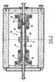
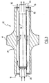
- FIGS. 1 and 2 correspond to a first embodiment of the simple filtration device and FIG. an embodiment for tangential filtration.
- FIGS. 1 and 2 correspond to a first embodiment of the simple filtration device and FIG. an embodiment for tangential filtration.
- FIGS. 1 and 2 correspond to a first embodiment of the simple filtration device
- FIG. an embodiment for tangential filtration.
- the corresponding elements are designated by the same references.
- the ultrasonic treatment modular unit 12 or tubular ultrasonic reactor 12 consists mainly of three essential characteristics.
- the modular unit 12 firstly comprises a tubular metal body 11 having an inner surface 13 of cylindrical and circular cross section.
- the tubular metal body 11 is open at its two ends, that is to say at its supply end 10 and at its discharge end 15 respectively. These two feed and discharge ends 10, 15 will be coupled with supply and exhaust ducts themselves possibly equipped with circulation pumps. This part of the installation is not shown since it uses very standard organs well known to those skilled in the art.
- the modular unit 12 also comprises on the outer surface of the tubular metal body 11, in the vicinity of the nodal zone thereof, a ring 17 coaxial with said tube, said ring projecting radially outwardly from the free surface of the tubular body 11.
- the modular unit 12 comprises at least one ultrasonic converter 19 which is arranged radially and integrally with said ring 17 at the periphery of the latter.
- the frequency of said converter 19 is equal to the vibration frequency of said ring 17 and to the longitudinal vibration frequency of the tubular metal body 11.
- ultrasonic converter 19 is used for a conventional converter, for example of the piezoelectric excitation type. It may for example be of the "Langevin Triplet" type as described in the book High Intensity Ultrasonics by B. Brown and J. E. Goodman.
- the coaxial ring 17 is machined in the mass
- the ring 17 is connected to the outer surface of the tubular body 11 by means of connecting fillets 21.
- the tubular metal body 11 has, according to the embodiment described, a length equal to half a wavelength for the frequency that it is desired to use. It should be noted in this regard that the frequency of the ultrasonic vibration delivered by the transmitter or the converter 19 will also be between 5 and 100 kHz. In this particular embodiment, the length of the tubular metal body is strictly equal to half a wavelength of the frequency of the ultrasonic vibration.
- connection of this metal portion with the modular unit 12 may for example be performed at the level of longitudinal amplitude of the bellows (stress nodes) by means of threads, shanks to force, welds or the like or be machined in the mass.
- the modular ultrasonic treatment unit 12 may be a SONITUBE 20 or 35 kHz marketed by SODEVA.
- a pump makes the liquid to be filtered enter one of the ends of the modular ultrasonic reactor 12.
- the liquid to be filtered thus enters the filter element 14 through the room 16 or 18. If the input part is the part 16, the liquid is filtered by the filtering element 14 from the inside to the outside, before emerging through the holes 20 drilled in the part 18.
- the pressure gradient existing in the device can be adjusted by adjusting the flow rate of the pump not shown, located upstream of the device and / or by adjusting the opening of a valve located downstream of the device.
- Pressure measurement gauges located upstream and downstream of the device can advantageously complete the device, all of which can be installed, if necessary in an industrial installation controlled by a programmable controller.
- the input part in the modular ultrasonic reactor 12 is the part 18; in this variant, the liquid to be filtered enters said modular ultrasonic reactor 12 through the holes 20 drilled in the workpiece 18, then is filtered by the filter element 14 from the outside to the inside, before coming out of the workpiece 16 .
- the closure and connection means 22 have an additional bore allowing double communication of the tubular ultrasonic reactor 12 with the external medium.
- a first communication takes place through the central bore 24 and communicates the interior of the filter element 14 with the external medium.
- a second communication takes place by the additional drilling 26 and communicates the outside of the filter element 14.
- the liquid to be filtered enters the ultrasonic modular reactor 12 through the holes drilled in the room 28.
- the arrows shown in Figure 3 materialize the liquid flow paths.
- the liquid is divided into two parts: the first part passes through and is filtered by the filter element 14 from outside to inside, before emerging from the modular ultrasonic reactor 12 through the central bore 24 of the part 22, while the second liquid part flows tangentially to the filter element 14 before emerging from said reactor by the additional drilling 26.
- the present invention when placed in a liquid circuit, it can be subject to a periodic cleaning against the current of the filter element, triggered preferably automatically, as soon as the pressure difference existing between the upstream and downstream of said filter element exceeds a predetermined threshold.
- the present invention continuously employs ultrasonic vibration to improve the filtration process. It thus makes it possible to obtain a homogeneous distribution of the ultrasonic power in contact with the filtering surface.
- the tubular ultrasonic reactor 12 is a 35 kHz standard SONITUBE from SODEVA company 225 mm long and 20 mm internal diameter, arranged in a vertical position.
- the filter element 14 used is type Poremet 5 ⁇ m absolute; it has an outer diameter of 12 mm and a length of 225 mm.
- the suspension is pumped from a stirred tank with a flow rate of 10 liters per minute. It circulates in the tubular ultrasonic reactor 12 from bottom to top and passes through the filter element 14 from the inside to the outside.
- the particle size analysis of the suspension shows that the passer is greater than 99% by mass of the solid phase.
- the upstream pressure rises rapidly and the liquid stops passing through the filter element 14 after about 1 minute. There is clogging of said filter element.
- the pressure remains constant at any point of the circuit, the pressure drop within the tubular ultrasonic reactor being less than 100 mb.
- the filter retained 3.6 g of particles but kept its porosity.
- the tubular ultrasonic reactor 12 is a standard SODEVA 20 kHz SONITUBE 370 mm long and 50 mm internal diameter, arranged in a vertical position and mounted in tangential filtration, valves located downstream of said filter element. for modulating the pressure difference between upstream and downstream of said filter element.
- the filter element used is a Poremet filter 10 ⁇ m in diameter 40 mm and 30 mm long.
- the suspension is first deagglomerated in the lower part of the tubular ultrasonic reactor 12 having no filter. A fraction of the liquid passes through the filter element with most of the particles smaller than 10 microns while a smaller fraction of the liquid entrains the other particles and remains outside the filter element before leaving the reactor . During the operation, it is found that the pressures remain constant until exhaustion of the 50 liters of suspension.
- a third example uses a sonitube standard 35 kHz tubular ultrasonic reactor 12 of the SODEVA company 225 mm long and 20 mm internal diameter, arranged in a horizontal position, according to an embodiment as illustrated in Figures 1 and 2.
- the filter element 14 is a Poremet filter 2 ⁇ m , with a diameter of 12 mm and a length of 225 mm.
- the objective is to eliminate particles larger than 2 ⁇ m .
- the suspension is pumped at a rate of 5 liters per minute.
- the pressure difference between upstream and downstream of the filter element does not exceed 1 bar after 20 minutes, despite the formation of a refusal layer of about 3 mm around the filter element.
- a simple counter-current operation without ultrasound makes it possible to recover the rejections while regenerating the filter element by eliminating all the particles stuck in the pores of said filter element.
Landscapes
- Chemical & Material Sciences (AREA)
- Chemical Kinetics & Catalysis (AREA)
- Filtration Of Liquid (AREA)
- Apparatuses For Generation Of Mechanical Vibrations (AREA)
- Filtering Materials (AREA)
- Separation Using Semi-Permeable Membranes (AREA)
- Physical Water Treatments (AREA)
- General Preparation And Processing Of Foods (AREA)
- Distillation Of Fermentation Liquor, Processing Of Alcohols, Vinegar And Beer (AREA)
- Electrical Discharge Machining, Electrochemical Machining, And Combined Machining (AREA)
- Manufacture And Refinement Of Metals (AREA)
Claims (11)
- Vorrichtung zum kontinuierlichen Filtrieren von Flüssigkeiten mit einem Filtrierungselement (14) innerhalb eines Gehäuses, das durch einen Ultraschallwandler (19) in Ultraschallschwingungen versetzt wird, dadurch gekennzeichnet, dass
das Gehäuse ein röhrenförmiger metallischer Körper (11) mit zylindrischer Innenfläche (13) und kreisförmigem Querschnitt ist, der an seinen zwei Enden für den Einlass (10) und den Auslass (15) offen ist, wobei die Außenfläche des röhrenförmigen metallischen Körpers in der Nähe der Knotenzone einen mit der Röhre koaxialen und radial vorspringenden Kragen (17) aufweist, wobei dieser Kragen an seinem Rand mit einem Ultraschallwandler (19) ausgestattet ist, der radial vorspringt und dessen Frequenz der Schwingungsfrequenz des Kragens (17) und der longitudinalen Schwingungsfrequenz des röhrenförmigen metallischen Körpers (11) entspricht, wobei der röhrenförmige metallische Körper (11), der Kragen (17) und der Ultraschallwandler (19) zusammen eine modulare Einheit (12) zur Ultraschallbehandlung bilden,
wobei das zylindrische Filtrierungselement (14) eine Oberfläche für die Filtrierung von wenigstens etwa 50 cm2 und vorzugsweise von etwa 80 cm2 mit einer Maschenweite von weniger als etwa 20 µm aufweist und in dem röhrenförmigen metallischen Körper (11) in koaxialer Art und Weise zu letzterem zwischen dem Einlass- (10) und Auslassende (15) angeordnet ist,
wobei die nominale in den röhrenförmigen metallischen Körper abgegebene Ultraschallleistungsdichte größer als etwa 2 Watt pro cm2 der Filtrierungsoberfläche beträgt. - Vorrichtung nach Anspruch 1, dadurch gekennzeichnet, dass die Länge des röhrenförmigen metallischen Körpers (11) gleich einem ganzen Vielfachen der halben Wellenlänge der von dem Wandler erzeugten Ultraschallfrequenz ist, wobei der Innen- und Außendurchmesser des Kragens (17) so bestimmt wird, dass die Schwingungsfrequenz des Kragens bei der gleichen Ultraschallschwingungsfrequenz liegt wie die, die durch den Wandler (19) erzeugt wird.
- Vorrichtung nach einem der Ansprüche 1 und 2, dadurch gekennzeichnet, dass das zylindrische Filtrierungselement (14) ausgewählt wird unter metallischen gewebten oder nicht gewebten, auf metallischen Trägern aufgebrachten Filtern, synthetischen gewebten oder nicht gewebten, auf metallischen Trägern aufgebrachten Filtern, metallischen mehrlagigen gesinterten Filtern und mineralischen oder metallischen selbsttragend gesinterten Filtern.
- Vorrichtung nach einem der Ansprüche 1 bis 3, dadurch gekennzeichnet, dass das filtrierende zylindrische Element (14) mit dem röhrenförmigen metallischen Körper über Verbindungsteile verbunden ist, die derart aufgebaut sind, dass die zu filtrierende Flüssigkeit von außen nach innen in das filtrierende Element strömt.
- Vorrichtung nach einem der Ansprüche 1 bis 3, dadurch gekennzeichnet, dass das filtrierende zylindrische Element (14) mit dem röhrenförmigen metallischen Körper über Verbindungsteile verbunden ist, die so aufgebaut sind, dass die zu filtrierende Flüssigkeit von innen aus dem filtrierenden Element nach außen in Bezug auf letzteres strömt.
- Vorrichtung nach einem der Ansprüche 1 bis 3, dadurch gekennzeichnet, dass die Verbindungsteile zwischen dem röhrenförmigen metallischen Körper und dem filtrierenden zylindrischen Element wie auch der Kreis für die Umwälzung des Fluids, das behandelt werden soll, derart aufgebaut sind, dass die Filtrierung nach dem Prinzip der tangentialen Filtrierung abläuft.
- Verfahren zum Betreiben einer Vorrichtung zum Filtrieren nach einem der Ansprüche 1 bis 5, die in einem Umwälzkreis für die zu filtrierende Flüssigkeit integriert ist, wobei letztere es ermöglicht, den Druckunterschied zwischen dem Eingang und dem Ausgang der Vorrichtung zu messen und diesen Druckunterschied einzustellen, indem der Durchsatz der Flüssigkeit in dem Kreis und/oder der Druckverlust unterhalb der Vorrichtung geregelt wird.
- Verfahren zum Betreiben einer Filtrierungsvorrichtung nach einem der Ansprüche 1 bis 3, die in einem Umwälzungskreis für die zu filtrierende Flüssigkeit integriert ist, wobei letztere es ermöglicht, das Filtrierungselement wiederholt im Gegenstrom zu reinigen, wenn der bestehende Druckunterschied zwischen dem Eingang und dem Ausgang des Filtrierungselements einen vorgegebenen Schwellenwert übersteigt.
- Verfahren zum Betreiben einer Filtrierungsvorrichtung nach einem der Ansprüche 1 bis 6, dadurch gekennzeichnet, dass die Intensität der Kavitation in der zu filtrierenden Flüssigkeit durch Einstellung der Ultraschallschwingungsleistung und/oder durch Wahl der Form eines Verstärkers zwischen dem Ultraschallstrahler und der Außenfläche des Kragens eingestellt wird, der in der Nähe der Knotenzone des röhrenförmigen metallischen Körpers radial vorspringt.
- Ultraschallfilter, dadurch gekennzeichnet, dass er als Hintereinanderschaltung oder Parallelschaltung von mehreren modularen Einheiten für die Ultraschallerzeugung gemäß einem der Ansprüche 1 bis 6 aufgebaut ist, wobei ein zylindrisches Filtrierungselement verschlossen wird, gemäß einem der Ansprüche 1 bis 6, so dass sich eine Kette von mehreren Filtern ergibt.
- Ultraschallfilter nach Anspruch 10, dadurch gekennzeichnet, dass er mehrere Wandler umfasst, die parallel durch denselben Generator versorgt werden.
Applications Claiming Priority (5)
| Application Number | Priority Date | Filing Date | Title |
|---|---|---|---|
| FR0103387 | 2001-03-13 | ||
| FR0103387A FR2822083B1 (fr) | 2001-03-13 | 2001-03-13 | Dispositif de filtration en voie liquide et en continu mettant en oeuvre des ultrasons a haute densite de puissance |
| FR0107282A FR2822084B1 (fr) | 2001-03-13 | 2001-06-01 | Dispositif de filtration en voie liquide et en continu mettant en oeuvre des ultrasons a haute densite de puissance |
| FR0107282 | 2001-06-01 | ||
| PCT/FR2002/000889 WO2002072229A1 (fr) | 2001-03-13 | 2002-03-13 | Dispositif de filtration en voie liquide et en continu mettant en oeuvre des ultrasons a haute densite de puissance |
Publications (2)
| Publication Number | Publication Date |
|---|---|
| EP1372809A1 EP1372809A1 (de) | 2004-01-02 |
| EP1372809B1 true EP1372809B1 (de) | 2006-06-07 |
Family
ID=26212919
Family Applications (1)
| Application Number | Title | Priority Date | Filing Date |
|---|---|---|---|
| EP02722343A Expired - Lifetime EP1372809B1 (de) | 2001-03-13 | 2002-03-13 | Vorrichtung zum kontinuierlichen filtrieren von flüssigkeiten mittels ultraschall mit hoher leistungsdichte |
Country Status (10)
| Country | Link |
|---|---|
| US (1) | US7101485B2 (de) |
| EP (1) | EP1372809B1 (de) |
| JP (1) | JP4064820B2 (de) |
| AT (1) | ATE328653T1 (de) |
| CA (1) | CA2440860C (de) |
| DE (1) | DE60212097T2 (de) |
| DK (1) | DK1372809T3 (de) |
| ES (1) | ES2266484T3 (de) |
| FR (1) | FR2822084B1 (de) |
| WO (1) | WO2002072229A1 (de) |
Cited By (2)
| Publication number | Priority date | Publication date | Assignee | Title |
|---|---|---|---|---|
| DE102012004835A1 (de) * | 2012-03-13 | 2013-09-19 | Roland de Craigher | Entkeimung von Flüssigkeiten mittels Ultraschall, Vorrichtung, Verfahren und Verwendung |
| WO2015001143A1 (es) | 2013-07-03 | 2015-01-08 | Pusonics S.L. | Sistema ultrasónico para mezclar líquidos y medios multifásicos, y método |
Families Citing this family (9)
| Publication number | Priority date | Publication date | Assignee | Title |
|---|---|---|---|---|
| US7445716B2 (en) | 2004-01-05 | 2008-11-04 | Eaton Lp | Crossflow pressure liquid filtration with ultrasonic enhancement |
| US7846341B2 (en) * | 2006-12-04 | 2010-12-07 | Bacoustics, Llc | Method of ultrasonically treating a continuous flow of fluid |
| DE102008025169B4 (de) * | 2008-05-26 | 2013-06-06 | Gea Westfalia Separator Group Gmbh | Filtermodul |
| US9512013B2 (en) * | 2011-05-31 | 2016-12-06 | Empire Technology Development Llc | Piezoelectric discharge water purification |
| US9115013B2 (en) * | 2012-08-15 | 2015-08-25 | Green Age Technologies Llc | Fluid filtration system |
| CN102824999B (zh) * | 2012-08-30 | 2015-10-28 | 宁波新芝生物科技股份有限公司 | 一种大功率超声波换能组件及换能器 |
| USD718835S1 (en) * | 2013-06-21 | 2014-12-02 | Flodesign Sonics, Inc. | Acoustic separator |
| USD722674S1 (en) * | 2013-06-27 | 2015-02-17 | Flodesign Sonics, Inc. | Acoustic separator |
| CN107213684A (zh) * | 2017-07-29 | 2017-09-29 | 南通绣达服饰有限公司 | 一种多元合金水质处理工具 |
Family Cites Families (8)
| Publication number | Priority date | Publication date | Assignee | Title |
|---|---|---|---|---|
| DE3811706A1 (de) * | 1988-04-08 | 1989-10-19 | Reson System Aps | Verfahren zur filterreinigung und apparat zur ausuebung des verfahrens |
| FR2671737A1 (fr) * | 1991-01-17 | 1992-07-24 | Vaxelaire Philippe | Unite modulaire de reacteur ultra-sonique tubulaire. |
| GB9306174D0 (en) * | 1993-03-25 | 1993-05-19 | Leatherhead Food Ra | Ultrasonic cleaning |
| JPH08141325A (ja) * | 1994-11-18 | 1996-06-04 | Central Glass Co Ltd | 連続濾過装置 |
| FR2743929B1 (fr) * | 1996-01-24 | 1998-04-10 | Aev Engineering Sarl | Dispositif pour la generation d'ondes ultrasonores |
| FR2768941B1 (fr) * | 1997-09-26 | 1999-12-24 | Eif | Dispositif contre le colmatage d'un filtre |
| FR2769516A1 (fr) * | 1997-10-13 | 1999-04-16 | Andre Gabet | Nouveau dispositif de filtration a nettoyage automatique pour circuit de liquide |
| US6395186B1 (en) * | 2000-06-20 | 2002-05-28 | Delaware Capital Formation, Inc. | Pressure liquid filtration with ultrasonic bridging prevention |
-
2001
- 2001-06-01 FR FR0107282A patent/FR2822084B1/fr not_active Expired - Fee Related
-
2002
- 2002-03-13 AT AT02722343T patent/ATE328653T1/de not_active IP Right Cessation
- 2002-03-13 JP JP2002571184A patent/JP4064820B2/ja not_active Expired - Fee Related
- 2002-03-13 DK DK02722343T patent/DK1372809T3/da active
- 2002-03-13 ES ES02722343T patent/ES2266484T3/es not_active Expired - Lifetime
- 2002-03-13 US US10/472,024 patent/US7101485B2/en not_active Expired - Fee Related
- 2002-03-13 EP EP02722343A patent/EP1372809B1/de not_active Expired - Lifetime
- 2002-03-13 CA CA002440860A patent/CA2440860C/fr not_active Expired - Fee Related
- 2002-03-13 WO PCT/FR2002/000889 patent/WO2002072229A1/fr not_active Ceased
- 2002-03-13 DE DE60212097T patent/DE60212097T2/de not_active Expired - Lifetime
Cited By (2)
| Publication number | Priority date | Publication date | Assignee | Title |
|---|---|---|---|---|
| DE102012004835A1 (de) * | 2012-03-13 | 2013-09-19 | Roland de Craigher | Entkeimung von Flüssigkeiten mittels Ultraschall, Vorrichtung, Verfahren und Verwendung |
| WO2015001143A1 (es) | 2013-07-03 | 2015-01-08 | Pusonics S.L. | Sistema ultrasónico para mezclar líquidos y medios multifásicos, y método |
Also Published As
| Publication number | Publication date |
|---|---|
| JP4064820B2 (ja) | 2008-03-19 |
| DK1372809T3 (da) | 2006-10-02 |
| DE60212097T2 (de) | 2006-11-30 |
| JP2004523352A (ja) | 2004-08-05 |
| ATE328653T1 (de) | 2006-06-15 |
| DE60212097D1 (de) | 2006-07-20 |
| EP1372809A1 (de) | 2004-01-02 |
| WO2002072229A1 (fr) | 2002-09-19 |
| CA2440860A1 (fr) | 2002-09-19 |
| US7101485B2 (en) | 2006-09-05 |
| FR2822084B1 (fr) | 2003-12-12 |
| ES2266484T3 (es) | 2007-03-01 |
| FR2822084A1 (fr) | 2002-09-20 |
| CA2440860C (fr) | 2008-08-26 |
| US20040129643A1 (en) | 2004-07-08 |
Similar Documents
| Publication | Publication Date | Title |
|---|---|---|
| EP1372809B1 (de) | Vorrichtung zum kontinuierlichen filtrieren von flüssigkeiten mittels ultraschall mit hoher leistungsdichte | |
| FR2638659A1 (fr) | Appareil de filtration comportant un dispositif de decolmatage par ultrasons et procede de decolmatage correspondant | |
| CA2192107C (fr) | Element tubulaire inorganique de filtration comportant des canaux de section non circulaire presentant des profils optimises | |
| EP1736233B1 (de) | Anorganisches Mehrkanal-Filterelement zum Filtrieren von Fluiden | |
| EP0183583A1 (de) | Ultraschallgenerator | |
| EP0332788A1 (de) | Verfahren zur Behandlung verunreinigter Öl-in-Wasser-Emulsionen oder-Mikroemulsionen | |
| FR2671737A1 (fr) | Unite modulaire de reacteur ultra-sonique tubulaire. | |
| EP0154295B1 (de) | Trennvorrichtung mit Membranen und Verfahren zu ihrer Herstellung | |
| EP3302767A1 (de) | Einstückige säulen struktur zur trennung eines flüssigmediums | |
| FR2957267A1 (fr) | Nouvelle geometrie de support et membrane de filtration | |
| EP1562694B1 (de) | Querstromfiltrationsmembran und verfahren zu ihrer herstellung | |
| FR2822083A1 (fr) | Dispositif de filtration en voie liquide et en continu mettant en oeuvre des ultrasons a haute densite de puissance | |
| EP0120750A1 (de) | Vorrichtung zur tangentialen Filterung und diese Vorrichtung umfassende Anlage | |
| FR2549745A1 (fr) | Procede de nettoyage par ultra-sons de surfaces et dispositif et installation mettant en oeuvre le procede | |
| EP0229414B1 (de) | Vorrichtung zur Reinigung von Wasser, insbesondere Salzwasser, durch Umkehrosmose | |
| EP2021108B1 (de) | Verfahren zur reinigung der membran einer vorrichtung zur querstromfilteration von wein | |
| CA2563317C (fr) | Support a porosite modifiee et membrane pour la filtration tangentielle d'un fluide | |
| FR2504405A1 (fr) | Procede et dispositif pour nettoyer ou filtrer des suspensions de materiaux, applicables, notamment, a l'industrie du papier | |
| WO2006059006A1 (fr) | Support inorganique de filtration d'un milieu fluide avec des caracteristiques geometriques optimisees | |
| WO1998057724A1 (fr) | Procede et dispositifs de decolmatage de filtres | |
| FR2815269A1 (fr) | Dispositif et installation pour la filtration tangentielle incluant un mode de fonctionnement en retrofiltration | |
| FR3098415A1 (fr) | Dispositif de filtration de fluide et procedes associes | |
| FR2575501A1 (fr) | Procede de decolmatage des puits ainsi qu'appareillage pour la mise en oeuvre de ce procede | |
| FR3036627A1 (fr) | Element de separation avec un acheminement direct du filtrat |
Legal Events
| Date | Code | Title | Description |
|---|---|---|---|
| PUAI | Public reference made under article 153(3) epc to a published international application that has entered the european phase |
Free format text: ORIGINAL CODE: 0009012 |
|
| 17P | Request for examination filed |
Effective date: 20031009 |
|
| AK | Designated contracting states |
Kind code of ref document: A1 Designated state(s): AT BE CH CY DE DK ES FI FR GB GR IE IT LI LU MC NL PT SE TR |
|
| AX | Request for extension of the european patent |
Extension state: AL LT LV MK RO SI |
|
| 17Q | First examination report despatched |
Effective date: 20040301 |
|
| RIN1 | Information on inventor provided before grant (corrected) |
Inventor name: DUBRUQUE, DOMINIQUE Inventor name: VAXELAIRE, PHILIPPE Inventor name: BOURSIER, GILLES |
|
| GRAP | Despatch of communication of intention to grant a patent |
Free format text: ORIGINAL CODE: EPIDOSNIGR1 |
|
| GRAS | Grant fee paid |
Free format text: ORIGINAL CODE: EPIDOSNIGR3 |
|
| RAP1 | Party data changed (applicant data changed or rights of an application transferred) |
Owner name: SODEVA |
|
| GRAA | (expected) grant |
Free format text: ORIGINAL CODE: 0009210 |
|
| AK | Designated contracting states |
Kind code of ref document: B1 Designated state(s): AT BE CH CY DE DK ES FI FR GB GR IE IT LI LU MC NL PT SE TR |
|
| PG25 | Lapsed in a contracting state [announced via postgrant information from national office to epo] |
Ref country code: IT Free format text: LAPSE BECAUSE OF FAILURE TO SUBMIT A TRANSLATION OF THE DESCRIPTION OR TO PAY THE FEE WITHIN THE PRESCRIBED TIME-LIMIT;WARNING: LAPSES OF ITALIAN PATENTS WITH EFFECTIVE DATE BEFORE 2007 MAY HAVE OCCURRED AT ANY TIME BEFORE 2007. THE CORRECT EFFECTIVE DATE MAY BE DIFFERENT FROM THE ONE RECORDED. Effective date: 20060607 |
|
| REG | Reference to a national code |
Ref country code: GB Ref legal event code: FG4D Free format text: NOT ENGLISH |
|
| REG | Reference to a national code |
Ref country code: CH Ref legal event code: EP |
|
| REG | Reference to a national code |
Ref country code: IE Ref legal event code: FG4D Free format text: LANGUAGE OF EP DOCUMENT: FRENCH |
|
| REF | Corresponds to: |
Ref document number: 60212097 Country of ref document: DE Date of ref document: 20060720 Kind code of ref document: P |
|
| REG | Reference to a national code |
Ref country code: CH Ref legal event code: NV Representative=s name: MICHELI & CIE INGENIEURS-CONSEILS |
|
| REG | Reference to a national code |
Ref country code: SE Ref legal event code: TRGR |
|
| REG | Reference to a national code |
Ref country code: DK Ref legal event code: T3 |
|
| GBT | Gb: translation of ep patent filed (gb section 77(6)(a)/1977) |
Effective date: 20060921 |
|
| PG25 | Lapsed in a contracting state [announced via postgrant information from national office to epo] |
Ref country code: PT Free format text: LAPSE BECAUSE OF FAILURE TO SUBMIT A TRANSLATION OF THE DESCRIPTION OR TO PAY THE FEE WITHIN THE PRESCRIBED TIME-LIMIT Effective date: 20061107 |
|
| REG | Reference to a national code |
Ref country code: ES Ref legal event code: FG2A Ref document number: 2266484 Country of ref document: ES Kind code of ref document: T3 |
|
| PLBE | No opposition filed within time limit |
Free format text: ORIGINAL CODE: 0009261 |
|
| STAA | Information on the status of an ep patent application or granted ep patent |
Free format text: STATUS: NO OPPOSITION FILED WITHIN TIME LIMIT |
|
| 26N | No opposition filed |
Effective date: 20070308 |
|
| PG25 | Lapsed in a contracting state [announced via postgrant information from national office to epo] |
Ref country code: MC Free format text: LAPSE BECAUSE OF NON-PAYMENT OF DUE FEES Effective date: 20070331 |
|
| PG25 | Lapsed in a contracting state [announced via postgrant information from national office to epo] |
Ref country code: GR Free format text: LAPSE BECAUSE OF FAILURE TO SUBMIT A TRANSLATION OF THE DESCRIPTION OR TO PAY THE FEE WITHIN THE PRESCRIBED TIME-LIMIT Effective date: 20060908 |
|
| PG25 | Lapsed in a contracting state [announced via postgrant information from national office to epo] |
Ref country code: LU Free format text: LAPSE BECAUSE OF NON-PAYMENT OF DUE FEES Effective date: 20070313 Ref country code: CY Free format text: LAPSE BECAUSE OF FAILURE TO SUBMIT A TRANSLATION OF THE DESCRIPTION OR TO PAY THE FEE WITHIN THE PRESCRIBED TIME-LIMIT Effective date: 20060607 |
|
| PG25 | Lapsed in a contracting state [announced via postgrant information from national office to epo] |
Ref country code: TR Free format text: LAPSE BECAUSE OF FAILURE TO SUBMIT A TRANSLATION OF THE DESCRIPTION OR TO PAY THE FEE WITHIN THE PRESCRIBED TIME-LIMIT Effective date: 20060607 |
|
| REG | Reference to a national code |
Ref country code: FR Ref legal event code: CJ Ref country code: FR Ref legal event code: CD |
|
| PGFP | Annual fee paid to national office [announced via postgrant information from national office to epo] |
Ref country code: CH Payment date: 20100325 Year of fee payment: 9 Ref country code: DK Payment date: 20100310 Year of fee payment: 9 Ref country code: ES Payment date: 20100324 Year of fee payment: 9 Ref country code: IE Payment date: 20100325 Year of fee payment: 9 |
|
| PGFP | Annual fee paid to national office [announced via postgrant information from national office to epo] |
Ref country code: FI Payment date: 20100312 Year of fee payment: 9 Ref country code: FR Payment date: 20100402 Year of fee payment: 9 |
|
| PGFP | Annual fee paid to national office [announced via postgrant information from national office to epo] |
Ref country code: AT Payment date: 20100311 Year of fee payment: 9 Ref country code: GB Payment date: 20100322 Year of fee payment: 9 |
|
| PGFP | Annual fee paid to national office [announced via postgrant information from national office to epo] |
Ref country code: DE Payment date: 20100324 Year of fee payment: 9 Ref country code: IT Payment date: 20100327 Year of fee payment: 9 Ref country code: NL Payment date: 20100315 Year of fee payment: 9 |
|
| PGFP | Annual fee paid to national office [announced via postgrant information from national office to epo] |
Ref country code: BE Payment date: 20100506 Year of fee payment: 9 |
|
| PGFP | Annual fee paid to national office [announced via postgrant information from national office to epo] |
Ref country code: SE Payment date: 20100312 Year of fee payment: 9 |
|
| BERE | Be: lapsed |
Owner name: *SODEVA Effective date: 20110331 |
|
| REG | Reference to a national code |
Ref country code: NL Ref legal event code: V1 Effective date: 20111001 |
|
| REG | Reference to a national code |
Ref country code: CH Ref legal event code: PL Ref country code: DK Ref legal event code: EBP |
|
| REG | Reference to a national code |
Ref country code: SE Ref legal event code: EUG |
|
| GBPC | Gb: european patent ceased through non-payment of renewal fee |
Effective date: 20110313 |
|
| PG25 | Lapsed in a contracting state [announced via postgrant information from national office to epo] |
Ref country code: FI Free format text: LAPSE BECAUSE OF NON-PAYMENT OF DUE FEES Effective date: 20110313 Ref country code: AT Free format text: LAPSE BECAUSE OF NON-PAYMENT OF DUE FEES Effective date: 20110313 |
|
| REG | Reference to a national code |
Ref country code: FR Ref legal event code: ST Effective date: 20111130 |
|
| PG25 | Lapsed in a contracting state [announced via postgrant information from national office to epo] |
Ref country code: BE Free format text: LAPSE BECAUSE OF NON-PAYMENT OF DUE FEES Effective date: 20110331 |
|
| REG | Reference to a national code |
Ref country code: IE Ref legal event code: MM4A |
|
| PG25 | Lapsed in a contracting state [announced via postgrant information from national office to epo] |
Ref country code: IE Free format text: LAPSE BECAUSE OF NON-PAYMENT OF DUE FEES Effective date: 20110314 Ref country code: NL Free format text: LAPSE BECAUSE OF NON-PAYMENT OF DUE FEES Effective date: 20111001 Ref country code: CH Free format text: LAPSE BECAUSE OF NON-PAYMENT OF DUE FEES Effective date: 20110331 Ref country code: LI Free format text: LAPSE BECAUSE OF NON-PAYMENT OF DUE FEES Effective date: 20110331 Ref country code: DE Free format text: LAPSE BECAUSE OF NON-PAYMENT OF DUE FEES Effective date: 20111001 Ref country code: FR Free format text: LAPSE BECAUSE OF NON-PAYMENT OF DUE FEES Effective date: 20110331 |
|
| REG | Reference to a national code |
Ref country code: DE Ref legal event code: R119 Ref document number: 60212097 Country of ref document: DE Effective date: 20111001 |
|
| PG25 | Lapsed in a contracting state [announced via postgrant information from national office to epo] |
Ref country code: IT Free format text: LAPSE BECAUSE OF NON-PAYMENT OF DUE FEES Effective date: 20110313 Ref country code: GB Free format text: LAPSE BECAUSE OF NON-PAYMENT OF DUE FEES Effective date: 20110313 |
|
| REG | Reference to a national code |
Ref country code: ES Ref legal event code: FD2A Effective date: 20120423 |
|
| PG25 | Lapsed in a contracting state [announced via postgrant information from national office to epo] |
Ref country code: DK Free format text: LAPSE BECAUSE OF NON-PAYMENT OF DUE FEES Effective date: 20110331 |
|
| PG25 | Lapsed in a contracting state [announced via postgrant information from national office to epo] |
Ref country code: ES Free format text: LAPSE BECAUSE OF NON-PAYMENT OF DUE FEES Effective date: 20110314 |
|
| PG25 | Lapsed in a contracting state [announced via postgrant information from national office to epo] |
Ref country code: SE Free format text: LAPSE BECAUSE OF NON-PAYMENT OF DUE FEES Effective date: 20110314 |