EP1372876B1 - Procede et systeme de pressage hydrostatique a chaud - Google Patents
Procede et systeme de pressage hydrostatique a chaud Download PDFInfo
- Publication number
- EP1372876B1 EP1372876B1 EP01972426A EP01972426A EP1372876B1 EP 1372876 B1 EP1372876 B1 EP 1372876B1 EP 01972426 A EP01972426 A EP 01972426A EP 01972426 A EP01972426 A EP 01972426A EP 1372876 B1 EP1372876 B1 EP 1372876B1
- Authority
- EP
- European Patent Office
- Prior art keywords
- pressure
- working
- working liquid
- blank
- liquid
- Prior art date
- Legal status (The legal status is an assumption and is not a legal conclusion. Google has not performed a legal analysis and makes no representation as to the accuracy of the status listed.)
- Expired - Lifetime
Links
Images

Classifications
-
- B—PERFORMING OPERATIONS; TRANSPORTING
- B21—MECHANICAL METAL-WORKING WITHOUT ESSENTIALLY REMOVING MATERIAL; PUNCHING METAL
- B21C—MANUFACTURE OF METAL SHEETS, WIRE, RODS, TUBES, PROFILES OR LIKE SEMI-MANUFACTURED PRODUCTS OTHERWISE THAN BY ROLLING; AUXILIARY OPERATIONS USED IN CONNECTION WITH METAL-WORKING WITHOUT ESSENTIALLY REMOVING MATERIAL
- B21C23/00—Extruding metal; Impact extrusion
- B21C23/007—Hydrostatic extrusion
-
- B—PERFORMING OPERATIONS; TRANSPORTING
- B22—CASTING; POWDER METALLURGY
- B22F—WORKING METALLIC POWDER; MANUFACTURE OF ARTICLES FROM METALLIC POWDER; MAKING METALLIC POWDER; APPARATUS OR DEVICES SPECIALLY ADAPTED FOR METALLIC POWDER
- B22F3/00—Manufacture of workpieces or articles from metallic powder characterised by the manner of compacting or sintering; Apparatus specially adapted therefor ; Presses and furnaces
- B22F3/12—Both compacting and sintering
- B22F3/14—Both compacting and sintering simultaneously
- B22F3/15—Hot isostatic pressing
-
- B—PERFORMING OPERATIONS; TRANSPORTING
- B22—CASTING; POWDER METALLURGY
- B22F—WORKING METALLIC POWDER; MANUFACTURE OF ARTICLES FROM METALLIC POWDER; MAKING METALLIC POWDER; APPARATUS OR DEVICES SPECIALLY ADAPTED FOR METALLIC POWDER
- B22F3/00—Manufacture of workpieces or articles from metallic powder characterised by the manner of compacting or sintering; Apparatus specially adapted therefor ; Presses and furnaces
- B22F3/20—Manufacture of workpieces or articles from metallic powder characterised by the manner of compacting or sintering; Apparatus specially adapted therefor ; Presses and furnaces by extruding
-
- B—PERFORMING OPERATIONS; TRANSPORTING
- B30—PRESSES
- B30B—PRESSES IN GENERAL
- B30B11/00—Presses specially adapted for forming shaped articles from material in particulate or plastic state, e.g. briquetting presses, tabletting presses
- B30B11/22—Extrusion presses; Dies therefor
- B30B11/30—Extrusion presses; Dies therefor using directly-acting fluid pressure
-
- B—PERFORMING OPERATIONS; TRANSPORTING
- B22—CASTING; POWDER METALLURGY
- B22F—WORKING METALLIC POWDER; MANUFACTURE OF ARTICLES FROM METALLIC POWDER; MAKING METALLIC POWDER; APPARATUS OR DEVICES SPECIALLY ADAPTED FOR METALLIC POWDER
- B22F3/00—Manufacture of workpieces or articles from metallic powder characterised by the manner of compacting or sintering; Apparatus specially adapted therefor ; Presses and furnaces
- B22F3/20—Manufacture of workpieces or articles from metallic powder characterised by the manner of compacting or sintering; Apparatus specially adapted therefor ; Presses and furnaces by extruding
- B22F2003/206—Hydrostatic or hydraulic extrusion
-
- B—PERFORMING OPERATIONS; TRANSPORTING
- B22—CASTING; POWDER METALLURGY
- B22F—WORKING METALLIC POWDER; MANUFACTURE OF ARTICLES FROM METALLIC POWDER; MAKING METALLIC POWDER; APPARATUS OR DEVICES SPECIALLY ADAPTED FOR METALLIC POWDER
- B22F2999/00—Aspects linked to processes or compositions used in powder metallurgy
Definitions
- This invention relates to methods of extrusion and isostatic pressing and particularly to methods using high-temperature pressing.
- the invention belongs to the methods of hot hydrostatic pressing, wherein the blanks are heated to temperatures above the 600-700°C range, such as hot extrusion of metals and sintered billets, HIP-ping (Hot Isostatic Pressure), hot compacting of powders and deposited powder materials, plastic deformation under high isostatic pressure, etc.
- HIP-ping Hot Isostatic Pressure
- Pressing in inert or reactive gases is performed in pressurized autoclaves (gasostats) at pressures up to 1500-2000 atm and temperatures up to 2000°C.
- gasostats pressurized autoclaves
- a basic shortcoming of the "gas" pressing is the relatively low attainable pressure and the high complexity of the equipment.
- the power consumption per unit weight of the blank is high due to the great compressibility of the working gas and the impossibility to recuperate the compressed gas energy. Since the blanks are heated inside the gasostat, the working gas and the autoclave chamber are heated as well, contributing to energy losses.
- the low attainable pressure in the "gas" pressing is a major limitation for such pressing methods as HIP-ping and compacting processes, where it significantly prolongs the seasoning time of the blank. A typical gasostat working cycle in such a process takes 6-8 hours. Besides, the low pressure prevents obtaining of high-quality compacted powders and deposited materials.
- JP 01269509 discloses a method of using a low-temperature working liquid for pressing resin powder at high temperature by filling the heated powder in a heat-insulated capsule with heat-insulated rubber cover and pressing the capsule in a hydrostatic press by means of said working liquid.
- the capsule and the cover protect the working liquid from contact with the heated powder during the whole processing time. Consequently, the method is limited to temperatures that a rubber cover may endure, e.g. 500-600°C.
- US 3,931,382 presents a method for compacting preheated powder bodies in a high pressure isostatic pressure vessel in which a liquid such as water is used as pressurizing medium.
- a preheated workpiece is inserted into a shielding container having an open upper end and then the container is inserted into the pressure vessel which is closed and sealed.
- the vessel is then rapidly filled with the liquid pressurizing medium while the shielding container prevents contact of the medium with the preheated workpiece until the vessel is almost full.
- the pressure within the vessel is then increased rapidly to a preselected compacting level by continually pumping the liquid pressurizing medium into the vessel.
- the preselected compacting pressure is in excess of the critical pressure of the liquid pressurizing medium.
- the rapid increase of pressure within the vessel to a level exceeding the critical (stabilization) pressure minimizes the amount of vapor that is formed in the vessel and reduces heat transfer from the preheated body to the pressurizing system.
- This method allows the usage of cheap working liquids such as mineral oils with low internal friction for high-temperature and high-pressure hydrostatic pressing.
- the working liquid is of low compressibility and does not pose limitations to raising the working pressure.
- the method is energy efficient since only the blank needs to be heated; it is time efficient since the processing time, e.g. for curing defects, is less at higher temperatures and pressures, and there is no waiting period for cooling down of the press equipment between processing cycles.
- the liquid when a liquid like oil or water is brought in contact with a hot surface, the liquid starts to evaporate very intensively forming a gaseous "cushion" at the contact interface.
- the gaseous cushion has low thermal conductivity, which retards further evaporation. If the surface is very hot, the liquid may start to boil, to burn, to explode, or to char, thus destroying the interface gaseous cushion in a short transition time. However, if the pressure of the liquid is sufficiently high, the gaseous interface layer may be stabilized even on a very hot surface. Based on this phenomenon, the method of the present invention is to raise rapidly the pressure of the working fluid, after it comes into contact with the hot blank, and reach a high stabilization pressure in a time shorter than said transition time.
- the value of the stabilization pressure depends on the kind of working liquid and the blank temperature. Practically, it appears that a pressure of the order 6000-8000 atm is sufficient.
- the transition time after the contact between the working liquid and the hot blank, in which the stability of the gaseous layer is lost if the stabilization pressure is not attained also depends on the blank temperature and the working liquid properties. Practically, "safe" times for attaining the stabilization pressure appear to be less than tenths of a second.
- the velocity of the press plunger has to be quite high, at least during the pressure gain stroke. This velocity depends on the volumes of the chamber and the blank, on the specific pressing process, etc. and in practice appears to be about 150-500 mm/s.
- the power plant of the press must deliver huge power rates, for example, for a 1200 t press facility, at 200 mm/s velocity, the required power rate will be more than 2500 kW.
- a short-time pulse of such power rate can be conveniently delivered by a hydraulic press with a powerful accumulation station.
- a screw press with a flywheel may be also used if the flywheel is able to accumulate the necessary energy.
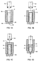
- Fig. 1 shows a system for hot hydrostatic extrusion according to the invention and stages of the extrusion process performed on a heated blank 2 by means of a working liquid 4 and a metallic cover (capsule) 6.
- the extrusion is carried out in a hydraulic or other press having a working chamber 10, a plunger 12 movable into the chamber and sealed thereto by a seal assembly 14.
- the working chamber 10 is closed by an extrusion die 16 with an extrusion opening 18 and a guiding surface 20.
- the system is equipped with devices, not shown in the drawing, for heating the blank 2, for inserting the blank 2 and the capsule 6 in the working chamber 10, and for feeding the working fluid 4 into the working chamber.
- a heated blank is inserted in the working chamber 10.
- the capsule 6 is inserted to encase the blank with a loose fit but tightly fitting the extrusion die 18.
- the working chamber is filled with the working liquid 4, and at stage (d), the plunger 12 moves into the working chamber 10 rapidly raising the pressure at least to the stabilization pressure.
- the metallic capsule 6 shrinks tight around the blank and starts to transmit uniformly the external pressure there upon. Also, a heat contact between the heated blank and the working liquid is established and intensive heat transfer starts via the metallic capsule 6. The heat transfer does not develop before the shrinkage, due to the insulating air gap between the capsule and the blank. From the moment of contact on, the pressure must be raised to the stabilization pressure during a time less than the transition time to the state of liquid instability.
- the plunger moves further. Under the high working pressure, the blank 2 is extruded through the die opening 18, conducted by the guiding surface 20.
- the capsule 6 may be extruded together with the blank to form a surface layer thereon (as shown in Fig. 1d), or may remain and be smashed in the working chamber.
- the role of the capsule is to delay the moment of contact between the hot blank and the working liquid until a pressure level close to the stabilization pressure is reached, such that further raise of pressure to the stabilization pressure can take less time than the transition time. After the moment of contact, the capsule may be destroyed.
- Fig. 2 shows a scheme for HIP-ping performed on a heated blank 2 by means of a working liquid 4 according to a second embodiment of the invention.
- the HIP-ping process is carried out in a hydraulic or other press having a working chamber 10 with a forechamber 30, a plunger 12 movable into the forechamber and the working chamber through a seal assembly 14.
- the working chamber 10 is separated from the forchamber 30 by a breakable membrane 32, and is closed by a flange 34.
- the system is equipped with devices, not shown in the drawing, for heating the blank 2, for inserting the blank 2 into the working chamber 10, and for feeding the working fluid 4 into the forechamber 30.
- the forechamber 30 is filled with working fluid 4 beforehand, the blank 2 is heated and inserted into the working chamber 10 with flange 34 removed. Then the flange 34 is secured in place and the plunger 12 is moved into the forechamber 30 to raise the pressure therein.
- the membrane 32 breaks open and lets the working fluid flood the working chamber 10 instantaneously and come into contact with the hot blank 2.
- the plunger 10 continues its motion and raises the pressure at least to the stabilization pressure level. Since, after membrane has been broken, the working liquid pressure is due first to fall, the breaking pressure is preferably higher than the stabilization pressure, such that after flooding the working chamber, the pressure can reach the stabilization pressure during a time less than the transition time to the state of liquid instability.
- the plunger starts the final compression stroke from a position very close to the blank and with some accumulated inertia, which reduces the necessary time for achieving the stabilization pressure.
- the plunger stops and the HIP-ping process is carried out for the required time duration.
- Fig. 3 shows a scheme for HIP-ping according to a third embodiment of the invention.
- the HIP-ping process is carried out in a hydraulic or other press having a working chamber 10 with a plunger 12 movable into the working chamber through a seal assembly 14.
- the plunger carries at its leading end a container 36 made of thin deformable material and filled with working liquid 4.
- the working chamber is closed by a flange 34.
- a blank 2 is heated and inserted into the working chamber 10 with flange 34 removed. Then the flange 34 is secured in place and the plunger 12 with the container 36 is moved into the working chamber 10. The container butts into the blank and starts to deform. Upon reaching some predetermined breaking pressure, the container 36 breaks open and lets the working fluid 4 flood the working chamber 10 instantaneously and come into contact with the hot blank 2. The plunger 10 continues its motion and raises the pressure at least to the stabilization pressure level.
- the further operation of this embodiment is essentially the same as in the second embodiment.
- the breaking membrane or the breaking container of the second and third embodiment may be used in the hot extrusion process of the first embodiment, or the heated blank may be inserted in the working chamber either from above or from beneath.
Landscapes
- Engineering & Computer Science (AREA)
- Mechanical Engineering (AREA)
- Manufacturing & Machinery (AREA)
- Physics & Mathematics (AREA)
- Fluid Mechanics (AREA)
- Press Drives And Press Lines (AREA)
- Forging (AREA)
- Shaping Metal By Deep-Drawing, Or The Like (AREA)
Claims (13)
- Procédé de pressage hydrostatique à chaud d'une pièce brute chauffée (2) dans une chambre de travail (10) d'une presse au moyen d'un liquide de travail (4), ledit liquide tendant à devenir instable en un temps de transition lorsqu'il est en contact avec ladite pièce brute (2) chauffée à une température de travail élevée et à une pression inférieure à la pression de stabilisation du liquide de travail, dans lequel le pressage de la pièce brute (2) chauffée à ladite température de travail élevée est effectué par le liquide de travail (4) à une pression de travail non inférieure à ladite pression de stabilisation, le procédé comprenant les étapes consistant à :fournir dans ladite chambre de travail (10) de ladite presse ladite pièce brute chauffée (2), ledit liquide de travail et un couvercle rétractable ou cassable (6 ; 32 ; 36) pour retarder le moment du contact de transfert de chaleur entre la pièce brute chauffée (2) et le liquide de travail (4) ;élever la pression du liquide de travail (4) à un niveau de pression donné sans contact de transfert de chaleur entre la pièce brute chauffée (2) et le liquide de travail (4) ;rétracter ou casser le couvercle rétractable ou cassable (6 ; 32 ; 36) pour établir, à la pression donnée, le contact de transfert de chaleur entre la pièce brute chauffée (2) et le liquide de travail (4) ;élever la pression du liquide de travail (4) au moins à ladite pression de stabilisation pendant une période temporelle après ledit contact qui est plus courte que ledit temps de transition.
- Procédé de pressage hydrostatique à chaud selon la revendication 1, dans lequel ledit niveau de pression donné est proche de ladite pression de stabilisation.
- Procédé de pressage hydrostatique à chaud selon l'une quelconque des revendications 1 ou 2, dans lequel ledit couvercle rétractable ou cassable est une capsule rétractable (6) formée de façon à entourer ladite pièce brute chauffée (2) de façon relâchée, ladite capsule (6) se rétractant autour de la pièce brute (2), produisant ainsi ledit contact de transfert de chaleur et la transmission uniforme de la pression après que ledit contact a été établi.
- Procédé de pressage hydrostatique à chaud selon l'une quelconque des revendications 1 à 3, dans lequel ledit couvercle rétractable ou cassable est une membrane cassable (32) définissant une chambre avant (30) dans ladite chambre de travail (10), le procédé comprenant les étapes consistant à :remplir ladite chambre avant (30) avec ledit liquide de travail (4) ; etélever la pression du liquide de travail (4) dans la chambre avant (30) audit niveau de pression donné pour ouvrir un passage pour le liquide de travail de la chambre avant (30) à la chambre de travail (10).
- Procédé de pressage hydrostatique à chaud selon l'une quelconque des revendications 1 à 3, dans lequel ladite chambre de travail (10) a un piston plongeur (12) pouvant se déplacer à l'intérieur, ledit couvercle rétractable ou cassable est un conteneur cassable déformable (36) fixé audit piston plongeur (12) sur le côté de la chambre de travail, le procédé comprenant les étapes consistant à :remplir ledit conteneur (36) avec ledit liquide de travail (4),déplacer ledit piston plongeur (12) avec ledit conteneur (36) dans ladite chambre de travail de façon à ce qu'il vienne en butée contre ladite pièce brute (2) avec ledit conteneur (36), moyennant quoi lorsqu'il atteint ledit niveau de pression donné, le conteneur (36) s'ouvre en se cassant et laisse le liquide de travail inonder la chambre de travail, etdéplacer encore plus ledit piston plongeur (12) de façon à élever la pression du liquide de travail (4) au moins à ladite pression de stabilisation.
- Procédé de pressage hydrostatique à chaud selon l'une quelconque des revendications 1 à 3, dans lequel l'élévation de la pression du liquide de travail est effectuée au moyen d'un agencement ayant des parties mécaniques mobiles, ladite étape comprenant l'établissement desdites parties mécaniques en mouvement, après quoi l'inertie desdites parties mécaniques est utilisée pour accélérer ladite élévation de pression.
- Système de pressage hydrostatique à chaud d'une pièce brute chauffée (2) au moyen d'un liquide de travail (4) tendant à devenir instable en un temps de transition lorsqu'il est en contact avec ladite pièce brute (2) chauffée à une température de travail élevée et à une pression inférieure à la pression de stabilisation du liquide de travail, le système comprenant :caractérisé en ce que :une presse avec une chambre de travail (10) ayant un orifice d'admission de liquide destiné à recevoir le liquide de travail (4) et étant adaptée pour recevoir au moins une pièce brute (2),un agencement à haute pression capable d'élever la pression du liquide de travail (4) dans la chambre de travail (10) au moins à ladite pression de stabilisation,un couvercle (6 ; 32 ; 36) prévu dans ladite chambre (10), le couvercle étant adapté pour retarder le moment du contact de transfert de chaleur entre ladite pièce brute chauffée (2) et ledit liquide de travail (4), ledit système étantledit couvercle est adapté pour se rétracter ou se casser de façon à établir ledit contact lorsque la pression du liquide de travail atteint un niveau de pression donné,ledit agencement à haute pression est apte à élever la pression du liquide de travail (4) dans la chambre de travail (10) au moins à ladite pression de stabilisation pendant un temps plus court que ledit temps de transition, après l'établissement dudit contact de transfert de chaleur dudit liquide de travail (4) avec ladite pièce brute chauffée (2).
- Système de pressage hydrostatique à chaud selon la revendication 7, dans lequel ledit niveau de pression donné est proche de ladite pression de stabilisation.
- Système de pressage hydrostatique à chaud selon l'une quelconque des revendications 7 ou 8, dans lequel ledit couvercle est une capsule rétractable (6) formée de façon à entourer ladite pièce brute chauffée (2) de façon relâchée et adaptée pour se rétracter autour de ladite pièce brute, produisant ainsi ledit contact de transfert de chaleur et une transmission de pression uniforme lorsque la pression du liquide de travail est élevée audit niveau de pression donné.
- Système de pressage hydrostatique à chaud selon la revendication 9, dans lequel
ledit système est adapté pour effectuer une extrusion à chaud,
ladite chambre de travail (10) a une ouverture de filière (16, 18) avec un élément de fixation (18) autour de ladite ouverture (18) sur le côté interne de la chambre (10) ;
soit ladite capsule rétractable (6), soit la pièce brute chauffée (2) est adaptée pour s'ajuster de façon hermétique avec l'élément de fixation (18), permettant de cette manière l'extrusion de la pièce brute chauffée (2) par l'ouverture de filière (18). - Système de pressage hydrostatique à chaud selon l'une quelconque des revendications 7 ou 8, dans lequel ledit couvercle est une membrane cassable (32) définissant une chambre avant (30) dans ladite chambre de travail (10), ladite chambre avant comprenant ledit orifice d'admission de liquide de travail.
- Système de pressage hydrostatique à chaud selon l'une quelconque des revendications 7 ou 8, comprenant en outre un piston plongeur (12) capable de se déplacer le long de la chambre de travail (10) en étant ajusté à celle-ci de façon hermétique, dans lequel
ledit couvercle est formé en conteneur fermé hermétiquement (36) fixé audit piston plongeur (12) sur le côté de la pièce brute reçue (2) et rempli avec ledit liquide de travail (4),
ledit conteneur (36) est adapté pour se casser après collision avec la pièce brute (2) lorsque la pression dans le conteneur (36) atteint ledit niveau de pression donné, faisant de cette manière s'écouler le liquide de travail (4) dans la chambre de travail (10), et
ledit piston plongeur (12) est capable de se déplacer encore après avoir inondé la chambre de travail (10), élevant ainsi la pression du liquide de travail (4) au moins à ladite pression de stabilisation pendant un temps plus court que ledit temps de transition. - Système de pressage hydrostatique à chaud selon la revendication 7, comprenant un agencement haute pression avec des parties mécaniques mobiles adaptées pour être réglées en mouvement et accélérées avant que le liquide de travail (4) soit amené audit contact avec la pièce brute chauffée (2) et pour utiliser ensuite l'inertie dudit mouvement pour élever la pression du liquide de travail (4) au moins à ladite pression de stabilisation, pendant un temps plus court que le temps de transition.
Applications Claiming Priority (3)
| Application Number | Priority Date | Filing Date | Title |
|---|---|---|---|
| IL13878500 | 2000-09-29 | ||
| IL13878500A IL138785A0 (en) | 2000-09-29 | 2000-09-29 | A method and a system for hot hydrostatic pressing |
| PCT/IL2001/000859 WO2002026409A2 (fr) | 2000-09-29 | 2001-09-11 | Procede et systeme de pressage hydrostatique a chaud |
Publications (2)
| Publication Number | Publication Date |
|---|---|
| EP1372876A2 EP1372876A2 (fr) | 2004-01-02 |
| EP1372876B1 true EP1372876B1 (fr) | 2005-12-28 |
Family
ID=11074687
Family Applications (1)
| Application Number | Title | Priority Date | Filing Date |
|---|---|---|---|
| EP01972426A Expired - Lifetime EP1372876B1 (fr) | 2000-09-29 | 2001-09-11 | Procede et systeme de pressage hydrostatique a chaud |
Country Status (7)
| Country | Link |
|---|---|
| US (1) | US7250131B2 (fr) |
| EP (1) | EP1372876B1 (fr) |
| AT (1) | ATE314162T1 (fr) |
| AU (1) | AU2001292191A1 (fr) |
| DE (1) | DE60116384T2 (fr) |
| IL (1) | IL138785A0 (fr) |
| WO (1) | WO2002026409A2 (fr) |
Families Citing this family (2)
| Publication number | Priority date | Publication date | Assignee | Title |
|---|---|---|---|---|
| RU2278766C2 (ru) * | 2004-07-08 | 2006-06-27 | Рустам Оскарович Кайбышев | Способ уплотнения изделия и устройство для его осуществления |
| US8074748B1 (en) * | 2009-02-20 | 2011-12-13 | Us Synthetic Corporation | Thermally-stable polycrystalline diamond element and compact, and applications therefor such as drill bits |
Family Cites Families (3)
| Publication number | Priority date | Publication date | Assignee | Title |
|---|---|---|---|---|
| SE340605B (fr) * | 1970-05-26 | 1971-11-29 | Asea Ab | |
| US3931382A (en) * | 1973-05-11 | 1976-01-06 | National Forge Company | Method for rapid isostatic pressing |
| JPH01269509A (ja) * | 1988-04-20 | 1989-10-27 | Kobe Steel Ltd | 樹脂粉末の温間静水圧加圧成形法 |
-
2000
- 2000-09-29 IL IL13878500A patent/IL138785A0/xx not_active IP Right Cessation
-
2001
- 2001-09-11 WO PCT/IL2001/000859 patent/WO2002026409A2/fr not_active Ceased
- 2001-09-11 US US10/380,284 patent/US7250131B2/en not_active Expired - Fee Related
- 2001-09-11 AT AT01972426T patent/ATE314162T1/de not_active IP Right Cessation
- 2001-09-11 EP EP01972426A patent/EP1372876B1/fr not_active Expired - Lifetime
- 2001-09-11 AU AU2001292191A patent/AU2001292191A1/en not_active Abandoned
- 2001-09-11 DE DE60116384T patent/DE60116384T2/de not_active Expired - Lifetime
Also Published As
| Publication number | Publication date |
|---|---|
| US20040035167A1 (en) | 2004-02-26 |
| DE60116384T2 (de) | 2006-09-07 |
| DE60116384D1 (de) | 2006-02-02 |
| US7250131B2 (en) | 2007-07-31 |
| AU2001292191A1 (en) | 2002-04-08 |
| EP1372876A2 (fr) | 2004-01-02 |
| WO2002026409A2 (fr) | 2002-04-04 |
| IL138785A0 (en) | 2001-10-31 |
| WO2002026409A3 (fr) | 2003-10-16 |
| ATE314162T1 (de) | 2006-01-15 |
Similar Documents
| Publication | Publication Date | Title |
|---|---|---|
| US4732556A (en) | Apparatus for synthesizing and densifying materials using a shape memory alloy | |
| US4142888A (en) | Container for hot consolidating powder | |
| JPH0336490A (ja) | マイクロ波加熱での等方プレスとそのための等方加圧方法 | |
| US5134260A (en) | Method and apparatus for inductively heating powders or powder compacts for consolidation | |
| US4856311A (en) | Apparatus and method for the rapid attainment of high hydrostatic pressures and concurrent delivery to a workpiece | |
| DE3166124D1 (en) | Method of manufacturing compacts from powder | |
| US5066454A (en) | Isostatic processing with shrouded melt-away mandrel | |
| EP1372876B1 (fr) | Procede et systeme de pressage hydrostatique a chaud | |
| US5110542A (en) | Rapid densification of materials | |
| US3931382A (en) | Method for rapid isostatic pressing | |
| US4797085A (en) | Forming apparatus employing a shape memory alloy die | |
| CN113732284B (zh) | 一种靶材热等静压成型方法及设备 | |
| US4904538A (en) | One step HIP canning of powder metallurgy composites | |
| US4738610A (en) | Isostatic press using a shape memory alloy | |
| CN117259750A (zh) | 一种金属粉末固结工艺及装置 | |
| US4441874A (en) | Apparatus for differential expansion volume compaction | |
| JPH041041B2 (fr) | ||
| JPH0544639B2 (fr) | ||
| SU1279750A1 (ru) | Устройство дл гор чего изостатического прессовани изделий жидкостью | |
| SU948538A1 (ru) | Устройство дл гор чего изостатического прессовани изделий из порошка | |
| US4447390A (en) | Method for hot-consolidating powder using staged temperature and pressure causing compaction from the outside inward | |
| JPS61270121A (ja) | 成形方法および装置 | |
| JPS6217001B2 (fr) | ||
| JPH0581360B2 (fr) | ||
| RU2154549C1 (ru) | Способ изготовления изделий цилиндрической формы из порошка карбида бора методом горячего прессования |
Legal Events
| Date | Code | Title | Description |
|---|---|---|---|
| PUAI | Public reference made under article 153(3) epc to a published international application that has entered the european phase |
Free format text: ORIGINAL CODE: 0009012 |
|
| 17P | Request for examination filed |
Effective date: 20030403 |
|
| AK | Designated contracting states |
Kind code of ref document: A2 Designated state(s): AT BE CH CY DE DK ES FI FR GB GR IE IT LI LU MC NL PT SE TR |
|
| AX | Request for extension of the european patent |
Extension state: AL LT LV MK RO SI |
|
| 17Q | First examination report despatched |
Effective date: 20041108 |
|
| GRAP | Despatch of communication of intention to grant a patent |
Free format text: ORIGINAL CODE: EPIDOSNIGR1 |
|
| GRAS | Grant fee paid |
Free format text: ORIGINAL CODE: EPIDOSNIGR3 |
|
| GRAA | (expected) grant |
Free format text: ORIGINAL CODE: 0009210 |
|
| AK | Designated contracting states |
Kind code of ref document: B1 Designated state(s): AT BE CH CY DE DK ES FI FR GB GR IE IT LI LU MC NL PT SE TR |
|
| PG25 | Lapsed in a contracting state [announced via postgrant information from national office to epo] |
Ref country code: FI Free format text: LAPSE BECAUSE OF FAILURE TO SUBMIT A TRANSLATION OF THE DESCRIPTION OR TO PAY THE FEE WITHIN THE PRESCRIBED TIME-LIMIT Effective date: 20051228 Ref country code: LI Free format text: LAPSE BECAUSE OF FAILURE TO SUBMIT A TRANSLATION OF THE DESCRIPTION OR TO PAY THE FEE WITHIN THE PRESCRIBED TIME-LIMIT Effective date: 20051228 Ref country code: AT Free format text: LAPSE BECAUSE OF FAILURE TO SUBMIT A TRANSLATION OF THE DESCRIPTION OR TO PAY THE FEE WITHIN THE PRESCRIBED TIME-LIMIT Effective date: 20051228 Ref country code: NL Free format text: LAPSE BECAUSE OF FAILURE TO SUBMIT A TRANSLATION OF THE DESCRIPTION OR TO PAY THE FEE WITHIN THE PRESCRIBED TIME-LIMIT Effective date: 20051228 Ref country code: CH Free format text: LAPSE BECAUSE OF FAILURE TO SUBMIT A TRANSLATION OF THE DESCRIPTION OR TO PAY THE FEE WITHIN THE PRESCRIBED TIME-LIMIT Effective date: 20051228 Ref country code: BE Free format text: LAPSE BECAUSE OF FAILURE TO SUBMIT A TRANSLATION OF THE DESCRIPTION OR TO PAY THE FEE WITHIN THE PRESCRIBED TIME-LIMIT Effective date: 20051228 |
|
| REG | Reference to a national code |
Ref country code: GB Ref legal event code: FG4D |
|
| REG | Reference to a national code |
Ref country code: CH Ref legal event code: EP |
|
| REG | Reference to a national code |
Ref country code: IE Ref legal event code: FG4D |
|
| REF | Corresponds to: |
Ref document number: 60116384 Country of ref document: DE Date of ref document: 20060202 Kind code of ref document: P |
|
| PG25 | Lapsed in a contracting state [announced via postgrant information from national office to epo] |
Ref country code: DK Free format text: LAPSE BECAUSE OF FAILURE TO SUBMIT A TRANSLATION OF THE DESCRIPTION OR TO PAY THE FEE WITHIN THE PRESCRIBED TIME-LIMIT Effective date: 20060328 Ref country code: GR Free format text: LAPSE BECAUSE OF FAILURE TO SUBMIT A TRANSLATION OF THE DESCRIPTION OR TO PAY THE FEE WITHIN THE PRESCRIBED TIME-LIMIT Effective date: 20060328 Ref country code: SE Free format text: LAPSE BECAUSE OF FAILURE TO SUBMIT A TRANSLATION OF THE DESCRIPTION OR TO PAY THE FEE WITHIN THE PRESCRIBED TIME-LIMIT Effective date: 20060328 |
|
| PG25 | Lapsed in a contracting state [announced via postgrant information from national office to epo] |
Ref country code: ES Free format text: LAPSE BECAUSE OF FAILURE TO SUBMIT A TRANSLATION OF THE DESCRIPTION OR TO PAY THE FEE WITHIN THE PRESCRIBED TIME-LIMIT Effective date: 20060408 |
|
| PG25 | Lapsed in a contracting state [announced via postgrant information from national office to epo] |
Ref country code: PT Free format text: LAPSE BECAUSE OF FAILURE TO SUBMIT A TRANSLATION OF THE DESCRIPTION OR TO PAY THE FEE WITHIN THE PRESCRIBED TIME-LIMIT Effective date: 20060529 |
|
| NLV1 | Nl: lapsed or annulled due to failure to fulfill the requirements of art. 29p and 29m of the patents act | ||
| REG | Reference to a national code |
Ref country code: CH Ref legal event code: PL |
|
| ET | Fr: translation filed | ||
| PG25 | Lapsed in a contracting state [announced via postgrant information from national office to epo] |
Ref country code: IE Free format text: LAPSE BECAUSE OF NON-PAYMENT OF DUE FEES Effective date: 20060911 |
|
| PG25 | Lapsed in a contracting state [announced via postgrant information from national office to epo] |
Ref country code: MC Free format text: LAPSE BECAUSE OF NON-PAYMENT OF DUE FEES Effective date: 20060930 |
|
| PLBE | No opposition filed within time limit |
Free format text: ORIGINAL CODE: 0009261 |
|
| STAA | Information on the status of an ep patent application or granted ep patent |
Free format text: STATUS: NO OPPOSITION FILED WITHIN TIME LIMIT |
|
| 26N | No opposition filed |
Effective date: 20060929 |
|
| REG | Reference to a national code |
Ref country code: IE Ref legal event code: MM4A |
|
| PG25 | Lapsed in a contracting state [announced via postgrant information from national office to epo] |
Ref country code: LU Free format text: LAPSE BECAUSE OF NON-PAYMENT OF DUE FEES Effective date: 20060911 Ref country code: TR Free format text: LAPSE BECAUSE OF FAILURE TO SUBMIT A TRANSLATION OF THE DESCRIPTION OR TO PAY THE FEE WITHIN THE PRESCRIBED TIME-LIMIT Effective date: 20051228 |
|
| PG25 | Lapsed in a contracting state [announced via postgrant information from national office to epo] |
Ref country code: CY Free format text: LAPSE BECAUSE OF FAILURE TO SUBMIT A TRANSLATION OF THE DESCRIPTION OR TO PAY THE FEE WITHIN THE PRESCRIBED TIME-LIMIT Effective date: 20051228 |
|
| PGFP | Annual fee paid to national office [announced via postgrant information from national office to epo] |
Ref country code: GB Payment date: 20150923 Year of fee payment: 15 |
|
| REG | Reference to a national code |
Ref country code: FR Ref legal event code: PLFP Year of fee payment: 16 |
|
| PGFP | Annual fee paid to national office [announced via postgrant information from national office to epo] |
Ref country code: FR Payment date: 20170330 Year of fee payment: 16 |
|
| GBPC | Gb: european patent ceased through non-payment of renewal fee |
Effective date: 20160911 |
|
| PG25 | Lapsed in a contracting state [announced via postgrant information from national office to epo] |
Ref country code: GB Free format text: LAPSE BECAUSE OF NON-PAYMENT OF DUE FEES Effective date: 20160911 |
|
| PGFP | Annual fee paid to national office [announced via postgrant information from national office to epo] |
Ref country code: DE Payment date: 20170331 Year of fee payment: 16 |
|
| PGFP | Annual fee paid to national office [announced via postgrant information from national office to epo] |
Ref country code: IT Payment date: 20170331 Year of fee payment: 16 |
|
| REG | Reference to a national code |
Ref country code: DE Ref legal event code: R119 Ref document number: 60116384 Country of ref document: DE |
|
| REG | Reference to a national code |
Ref country code: FR Ref legal event code: ST Effective date: 20180531 |
|
| PG25 | Lapsed in a contracting state [announced via postgrant information from national office to epo] |
Ref country code: DE Free format text: LAPSE BECAUSE OF NON-PAYMENT OF DUE FEES Effective date: 20180404 |
|
| PG25 | Lapsed in a contracting state [announced via postgrant information from national office to epo] |
Ref country code: IT Free format text: LAPSE BECAUSE OF NON-PAYMENT OF DUE FEES Effective date: 20170911 Ref country code: FR Free format text: LAPSE BECAUSE OF NON-PAYMENT OF DUE FEES Effective date: 20171002 |