EP1373111B1 - Enrouleuses servant a enrouler une bande de matiere, en particulier une bande de papier ou de carton, sous forme de rouleaux - Google Patents
Enrouleuses servant a enrouler une bande de matiere, en particulier une bande de papier ou de carton, sous forme de rouleaux Download PDFInfo
- Publication number
- EP1373111B1 EP1373111B1 EP02726201A EP02726201A EP1373111B1 EP 1373111 B1 EP1373111 B1 EP 1373111B1 EP 02726201 A EP02726201 A EP 02726201A EP 02726201 A EP02726201 A EP 02726201A EP 1373111 B1 EP1373111 B1 EP 1373111B1
- Authority
- EP
- European Patent Office
- Prior art keywords
- roll
- winding
- rolls
- additional
- winding machine
- Prior art date
- Legal status (The legal status is an assumption and is not a legal conclusion. Google has not performed a legal analysis and makes no representation as to the accuracy of the status listed.)
- Expired - Lifetime
Links
- 238000004804 winding Methods 0.000 title claims abstract description 136
- 239000000463 material Substances 0.000 title claims description 12
- 239000011111 cardboard Substances 0.000 title abstract description 3
- 239000011087 paperboard Substances 0.000 title abstract description 3
- 238000005096 rolling process Methods 0.000 title abstract 2
- 238000007789 sealing Methods 0.000 claims description 9
- 238000013016 damping Methods 0.000 claims description 6
- 230000001413 cellular effect Effects 0.000 claims description 5
- 239000011148 porous material Substances 0.000 claims description 3
- 229920001971 elastomer Polymers 0.000 claims description 2
- 239000000806 elastomer Substances 0.000 claims description 2
- 238000000034 method Methods 0.000 abstract description 2
- 239000000123 paper Substances 0.000 description 3
- 229910000831 Steel Inorganic materials 0.000 description 2
- 239000010959 steel Substances 0.000 description 2
- 241001295925 Gegenes Species 0.000 description 1
- 230000004323 axial length Effects 0.000 description 1
- 239000011324 bead Substances 0.000 description 1
- 230000006835 compression Effects 0.000 description 1
- 238000007906 compression Methods 0.000 description 1
- 238000010276 construction Methods 0.000 description 1
- 230000009191 jumping Effects 0.000 description 1
- 230000001681 protective effect Effects 0.000 description 1
- 210000002023 somite Anatomy 0.000 description 1
- 238000011144 upstream manufacturing Methods 0.000 description 1
Images


Classifications
-
- B—PERFORMING OPERATIONS; TRANSPORTING
- B65—CONVEYING; PACKING; STORING; HANDLING THIN OR FILAMENTARY MATERIAL
- B65H—HANDLING THIN OR FILAMENTARY MATERIAL, e.g. SHEETS, WEBS, CABLES
- B65H18/00—Winding webs
- B65H18/08—Web-winding mechanisms
- B65H18/14—Mechanisms in which power is applied to web roll, e.g. to effect continuous advancement of web
- B65H18/20—Mechanisms in which power is applied to web roll, e.g. to effect continuous advancement of web the web roll being supported on two parallel rollers at least one of which is driven
-
- B—PERFORMING OPERATIONS; TRANSPORTING
- B65—CONVEYING; PACKING; STORING; HANDLING THIN OR FILAMENTARY MATERIAL
- B65H—HANDLING THIN OR FILAMENTARY MATERIAL, e.g. SHEETS, WEBS, CABLES
- B65H19/00—Changing the web roll
- B65H19/22—Changing the web roll in winding mechanisms or in connection with winding operations
- B65H19/2238—The web roll being driven by a winding mechanism of the nip or tangential drive type
- B65H19/2246—The web roll being driven by a winding mechanism of the nip or tangential drive type and the roll being supported on two rollers
-
- B—PERFORMING OPERATIONS; TRANSPORTING
- B65—CONVEYING; PACKING; STORING; HANDLING THIN OR FILAMENTARY MATERIAL
- B65H—HANDLING THIN OR FILAMENTARY MATERIAL, e.g. SHEETS, WEBS, CABLES
- B65H2301/00—Handling processes for sheets or webs
- B65H2301/40—Type of handling process
- B65H2301/41—Winding, unwinding
- B65H2301/413—Supporting web roll
- B65H2301/4137—Supporting web roll on its outer circumference
- B65H2301/41372—Supporting web roll on its outer circumference rollers or balls arrangement
- B65H2301/41376—Supporting web roll on its outer circumference rollers or balls arrangement arranged in a non-stationary manner, i.e. changing according to actual roll diameter
-
- B—PERFORMING OPERATIONS; TRANSPORTING
- B65—CONVEYING; PACKING; STORING; HANDLING THIN OR FILAMENTARY MATERIAL
- B65H—HANDLING THIN OR FILAMENTARY MATERIAL, e.g. SHEETS, WEBS, CABLES
- B65H2301/00—Handling processes for sheets or webs
- B65H2301/40—Type of handling process
- B65H2301/41—Winding, unwinding
- B65H2301/414—Winding
- B65H2301/4148—Winding slitting
-
- B—PERFORMING OPERATIONS; TRANSPORTING
- B65—CONVEYING; PACKING; STORING; HANDLING THIN OR FILAMENTARY MATERIAL
- B65H—HANDLING THIN OR FILAMENTARY MATERIAL, e.g. SHEETS, WEBS, CABLES
- B65H2408/00—Specific machines
- B65H2408/20—Specific machines for handling web(s)
- B65H2408/23—Winding machines
- B65H2408/235—Cradles
Definitions
- the invention relates to a winding machine for winding a material web, with the features of the preamble of claim 1.
- carrier roll winding machines are known to be used to wind a divided by longitudinal sections paper or board web to wound rolls.
- winding the bobbins are aligned axially aligned side by side on the two support rollers, which support the entire weight of the bobbins.
- the web is fed after slitting either from below through the gap between the two support rollers to the winding bed, or from above via one of the two support rollers.
- the winding hardness should be as even as possible over the diameter of each winding roll for a set of bobbins and not exceed a predetermined value. Since the line load increases with increasing winding roll diameter, winding rolls with the required winding quality can only be produced up to a certain diameter with support roll winding machines without means for relieving the winding roll weight.
- a carrier roll winding machine in which the web is fed to the winding bed through the gap between the carrier rolls from below.
- the winding machine includes a discharge roll which can be pivoted about a support roll.
- the ejection roller is freely rotatably mounted on lateral, pivotable about the axis of the support roller pivoting arms.
- US 3,841,578 A shows a winding machine of the type mentioned, in which in addition to the two support rollers distressschwenkbare additional rollers are arranged which extend parallel to the support rollers and can be brought to the periphery of the winding roll to the plant when the winding roll ejected from the winding bed shall be.
- One of the two additional rollers serves to lift the winding roll over the support roller facing the other additional roller.
- the winding roll is supported by the other additional roller, which moves together with the winding roll to store the winding roll on a storage table can.
- US Pat. No. 4,516,735 A shows another winding machine with two support rollers on which the winding roller rests.
- a lever is pivotable about the axis of a carrier roll on which an ejection roller is mounted.
- a feeder for a new winding tube is also arranged.
- another lever is arranged, which carries a discharge roller and a separator.
- No. 6,056,330 shows a roller for a winding machine which carries on its surface a deformable layer of a cellular material.
- US 5 575 436 A shows a further winding machine with two support rollers whose surface is structured.
- US 4 580 740 shows a winding machine of Doppeltragwalzenwickler type, in which a discharge roller is arranged on a support roller.
- the ejection roller is at one
- US 4 580 740 shows a winding machine of Doppeltragwalzenwickler type, in which a discharge roller is arranged on a support roller.
- the ejection roller is mounted on a lever which is pivotable about the axis of the corresponding support roller.
- the invention has for its object to provide a carrier roll winding machine of the generic type, can be produced with high winding reliability with large diameter winding rolls and high winding quality.
- the carrier roll winding machine shown in the figures is used for winding a subdivided by longitudinal cuts paper or board web to bobbins.
- the up to 10 m wide paper or board web is withdrawn from a supply roll, not shown, from a supply roll, divided by longitudinal sections and then wound on sleeves 1.
- the carrier roll winding machine comprises two spaced closely spaced support rollers 2, 3, which are each connected to a rotary drive 4, 5.
- the two support rollers 2, 3 extend over the entire working width of the winding machine, ie the maximum width of the wound web. They consist of a cylindrical roller body made of steel with shaft journals on the front sides, with which they are mounted in the frame 6 of the winding machine and where the rotary drives 4, 5 attack.
- Their diameter is 350 mm to 1500 mm, preferably 500 mm to 950 mm, with an axial length of up to 10 m.
- a wear-resistant elastomer having a hardness of between 65 and 80 measured according to Shore A is advantageously used, as described in EP 0679595-A1.
- the thickness of the running layer is then 5 mm to 12 mm.
- An advantageous alternative is to produce the deformable running layer from a cellular plastic material having a multiplicity of uniformly distributed pores, as described in EPO 879 199-B1.
- the pore size is then less than 5 mm, preferably between 0.05 mm and 1 mm, and the modulus of compression K of the material is less than 10 MPa.
- This material is volume compressible, so that no lateral beads form when impressing a winding roll in the deformable layer.
- the two support rollers 2, 3 form a winding bed, in which rest the winding rollers 6 during winding.
- the winding bed, the divided by longitudinal sections web 7 is fed from below through the gap between the two support rollers 2, 3.
- Above the winding bed is in the frame of the winding machine over the entire working width extending pressure roller 12 can be raised and lowered stored.
- the pressure roller 12 which can be pressed against the winding rollers 6 from above, the weight of the winding rollers 6 on the support rollers 2, 3 can be increased at the beginning of the winding, if the weight of the winding rollers 6 is not sufficient for the desired winding hardness.
- each additional roller 8, 9 extends parallel to the support rollers 2, 3 over the length thereof and is freely rotatably mounted respectively at the free end of two pivot levers 10, 11.
- the second pivot lever of an additional roller 8, 9 is located on the other machine longitudinal side.
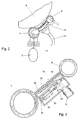
- the two pivot levers 10, 11 are pivotable about an axis parallel to the axis of the support roller 2, 3, preferably about the respective support roller axis itself, as shown in Figure 1.
- the two additional rollers 8, 9 are so from the outside towards each other and movable in the direction of the roller bed.
- Each of the pivot levers 10, 11 protrudes with a part beyond the respective support roller 2, 3, whose length is less than the maximum radius of a wound wound reel 6. As shown in Figure 1 is achieved so that the two additional rollers 8, 9 from create a certain winding roll diameter at a height below the winding tube 1 to the winding roller 6. For swiveling up and down the pivot levers 10, 11, these are connected to piston-cylinder units, which are not shown in the figures.
- the two additional rollers 8, 9 are like the support rollers 2, 3 constructed of a roller body made of steel, which has at each end face a shaft journal, which is in each case mounted in a pivot lever 10, 11. Its diameter is preferably slightly smaller than the diameter of the support rollers 2, 3. It is 200 mm to 600 mm. If the additional rollers - as in the present case - are also used as sealing rollers, they have a running layer of the above-described in the support rollers 2, 3 cellular and thus volume-compressible plastic material. The thickness of the overlay is 2% to 15% of the roll diameter.
- the additional rolls 8, 9 are provided with damping elements by which the vibrations of the winding rolls 6 are damped.
- damping elements friction damper or active damping elements are integrated either in the storage of additional rollers 8, 9 on the pivot levers 10, 11 or connected to the pivot lever 10, 11.
- each air box 13, 14 hang which has openings to the winding roller 6 and is connected to a compressed air supply. It can be so on each side below the winding roller 6 to generate an overpressure to reduce the contact weight.
- each air box 13, 14 is connected via a supply line 15 to a compressed air blower 16.
- the pressure in each air box 13, 14 can be adjusted with control valves 17, which are arranged in the respective supply line 15.
- the air chambers 13, 14 are each suspended between the pivot levers 11, 12 in the region between a support roller 2, 3 and the additional roller 8, 9 so that only a small gap between the air box 13, 14 and the respective support roller 2, 3 and respective additional roller 8, 9 remains.
- the additional rollers 8, 9 serve as sealing rollers which seal the pressure space below the winding roller 6 in the circumferential direction of the winding roller 6.
- the winding rollers 6 facing boundary wall 18 of an air box 13, 14 has a plurality of openings 19 through which the compressed air can escape in the direction of the winding roller 6: On the rear wall 20 of the air box 13, 14, the supply line 15 is connected.
- the effective width of an air chamber 13, 14 can be adapted to the width of the wound web 7, the two air boxes 13, 14 in the region of the possible positions of the longitudinal edges of the web 7 in individual, separately disconnectable chambers 20 are divided, which are transverse to Running direction of the web 7 extend.
- Each chamber 20 is separated on the one hand by a working width extending rear wall 21 of a common air supply chamber 22, on the other hand, it is separated from the adjacent chamber 20 by a transverse wall, not shown.
- the rear wall 21 has for each chamber 20 an opening 23 which can be closed and opened by means of a slide 24, respectively.
- Each slider 24 is actuated by a piston-cylinder unit 25, which are arranged in the common supply chamber 22.
- each air box 13, 14 is divided at its two lateral end portions into individual chambers 20, each having a measured in the axial direction of the rollers 3, 9 width of about 150 mm.
- the number of chambers 20 is determined as a function of the difference between the maximum and minimum width of a wound web 7 so that in each case the lateral areas of the air boxes 13, 14 can be closed outside the web 7, so there is no unacceptable compressed air losses.
- FIGS. 4 and 5 show ways of sealing the pressure chamber at the end faces of the winding rolls 6.
- a sealing shield 26 is displaceably mounted from the outside in the direction of the machine center.
- Each air box 13, 14 thus has on each machine longitudinal side a Abdichtschild 26 which seals the lateral opening between the air box 13, 14, the support rollers 2, 3, the additional rollers 8, 9 and the outer end face of the winding roller 6.
- the Abdicht ceremonies 26 are adapted at its bottom of the shape of the boundary wall 18 of the air box 13, 14, and at its lower lateral ends of the shape of the rollers 3, 9. They have a reaching into the region of a winding roller 6 part which seals against the end face of the winding roller 6.
- the Abdicht réelle 26 are positioned together with the edge knives of the upstream slitter.
- the edge knives cut the two longitudinal edges of the web 7. These two longitudinal sections are exactly in the transverse position in which the Abdicht réelle 26 must be positioned.
- FIG. 4 shows a particularly advantageous embodiment of a sealing shield 26.
- the sealing shield 26 is circular and is pushed by a spindle drive 27 transversely to the web 7 in its working position.
- the length of the pivot lever 10, 9 is chosen so large that the angle a between the connecting lines of the two additional rollers 8, 9 and the winding tube 1 is sufficiently large even at maximum winding roll diameter.
- the angle a is preferably more than 90 °.
- the winding rollers 6 are held in the region of the circumferential angle a of supporting elements in their position.
- the additional rollers 8, 9 are connected to damping elements, which counteract the vibrations of the bobbins 6 and thus prevent a rocking of the bobbins.
- FIG. 7 shows an embodiment in which the swivel arms 10, 11 with the additional rollers 8, 9 are advantageously used as parts of a reel changing device:
- the additional roller 8 at the web inlet side - in Figure 7 left - serves at the same time as a discharge role, are encountered with the finished wound bobbins 6 on the second support roller 3 from the winding bed.
- the bobbins 6 roll over the second support roller 3 on the second auxiliary roller 9, which is lowered so far that the bobbins 6 are received in a bed formed by the second support roller 3 and the additional roller 9.
- the second additional roller 9 is further lowered until the winding rollers 6 are at the floor level. There they are transported in a known manner by floor conveyors.
- the second, web outlet-side additional roller 9 with its pivot levers 11 so also takes on a task for which a separate lowering device is required in known roll-winding machines.
- the carrier roll winding machine is operated in a known manner without relieving the winding roll weight.
- the pivot arms 10, 11 with the additional rollers 8, 9 are pivoted and out of function.
- the pressure roller 12 is located on top of the bobbins 6 and increases the support weight of the bobbins 6 on the support rollers 2, 3, as long as the weight of the bobbins 6 is not sufficient.
- the winding roll weight is finally so large that in order to avoid an undesirably high winding hardness, the support weight on the support rollers 2, 3 must be reduced.
- the pivot arms 10, 11 with the additional rollers 8, 9 swung up until the additional rollers 8, 9 abut the winding rollers 6 ( Figure 9).
- the lateral Abdicht réelle 26 are moved against the end faces of the outer winding rollers 6, so that in each case the space between a support roller 2, 3, the associated additional roller 8, 9 and the winding roller 6 is completed pressure-tight.
- an overpressure is generated via the air boxes 13, 14 in this space, which reduces the contact weight of the bobbins 6 by the desired amount.
- the laterally outside of the winding rollers 7 located chambers 20 of each air box 13, 14 are closed, so that there escapes no compressed air.
- the support roll winding machine has the great advantage that when lowering the pivot arms 10, 11, the effective relief surface 28 permanently increases.
- the relief force increases as a product of the relief surface and the overpressure.
- the automatically resulting magnification of the relief surface automatically results in constant overpressure to an increased unloading force, which is required to compensate for the increasing bobbin weight. It is thus only a reduced increase in the air pressure required to keep the line load at the support lines of the winding rollers 6 on the support rollers 2, 3 constant.
Landscapes
- Winding Of Webs (AREA)
Abstract
Claims (12)
- Enrouleuse pour enrouler une bande de matériau, notamment une bande de papier ou de carton, en rouleaux, comprenant deux cylindres porteurs (2, 3) qui forment un lit d'enroulement dans lequel reposent les rouleaux (6) lors de leur enroulement et auquel la bande (7) est amenée par le dessous à travers la fente entre les deux cylindres porteurs (2, 3), un cylindre supplémentaire (8, 9) pouvant pivoter vers le haut dans la direction du lit d'enroulement étant disposé à l'extérieur à côté de chaque cylindre porteur (2, 3), chaque cylindre supplémentaire (8, 9) s'étendant parallèlement aux cylindres porteurs (2, 3) et étant monté à chaque fois à l'extrémité de leviers pivotants (10, 11) qui peuvent pivoter autour d'un axe parallèlement à l'axe des cylindres porteurs, de préférence autour de l'axe des cylindres porteurs voisin lui-même, et qui dépassent avec une partie radialement au-delà du cylindre porteur respectif (2, 3) dont la longueur est inférieure au rayon maximum d'un rouleau enroulé fini (6), caractérisée en ce que les cylindres supplémentaires (8, 9) s'étendent sur la longueur des cylindres porteurs (2, 3) et sont réalisés sous forme de cylindres porteurs supplémentaires qui lors de l'enroulement reçoivent une partie du poids du rouleau.
- Enrouleuse selon la revendication 1, caractérisée en ce que les cylindres porteurs (2, 3) présentent un diamètre de 350 mm à 1500 mm, de préférence de 500 mm à 900 mm, et les cylindres supplémentaires un diamètre de 200 mm à 600 mm.
- Enrouleuse selon la revendication 1 ou 2, caractérisée en ce que les cylindres supplémentaires présentent une couche de roulement constituée d'un matériau cellulaire en plastique, de volume compressible, dont l'épaisseur vaut 2 à 15% du diamètre du cylindre.
- Enrouleuse selon l'une quelconque des revendications 1 à 3, caractérisée en ce que la surface d'enveloppe extérieure d'un ou des deux cylindres porteurs (2, 3) présente une couche de roulement déformable de manière limitée.
- Enrouleuse selon la revendication 4, caractérisée en ce que la couche de roulement se compose d'un élastomère de faible usure avec une dureté mesurée selon Shore A comprise entre 65 et 80 et présente une épaisseur de 5 mm à 12 mm.
- Enrouleuse selon la revendication 1 à 4, caractérisée en ce que la couche de roulement est fabriquée à partir d'un matériau cellulaire en plastique ayant une pluralité de pores répartis uniformément.
- Enrouleuse selon l'une quelconque des revendications 1 à 6, caractérisée en ce qu'entre les deux leviers pivotants (10, 11) de chaque cylindre supplémentaire (8, 9) est accrochée à chaque fois une boîte à air (13) qui présente des ouvertures (19) dirigées vers le rouleau (6) et qui est raccordée à une alimentation en air comprimé (15).
- Enrouleuse selon la revendication 7, caractérisée en ce que les deux boîtes à air (13, 14) sont divisées dans la région des bords longitudinaux de la bande (7) en chambres individuelles (20) déconnectables de manière séparée, qui s'étendent transversalement à la direction d'avance de la bande (7).
- Enrouleuse selon la revendication 7 ou 8, caractérisée en ce que sur chaque levier pivotant (10, 11) est monté un écran d'étanchéité (26) pouvant être déplacé de l'extérieur dans la direction du milieu de la machine, qui réalise l'étanchéité de l'ouverture latérale entre la boîte à air (13, 14), les cylindres porteurs (2, 3), les cylindres supplémentaires (8, 9) et le côté frontal extérieur du rouleau (6).
- Enrouleuse selon l'une quelconque des revendications 1 à 9, caractérisée en ce que les cylindres supplémentaires (8, 9) sont connectés à des éléments d'amortissement qui s'opposent à des vibrations des rouleaux (6).
- Enrouleuse selon l'une quelconque des revendications 1 à 10, caractérisée en ce qu'un rouleau supplémentaire (8) sert de rouleau éjecteur, avec lequel les rouleaux enroulés finis (6) sont éjectés du lit d'enroulement.
- Enrouleuse selon l'une quelconque des revendications 1 à 11, caractérisée en ce qu'un cylindre supplémentaire (9) avec ses leviers pivotants (11) sert de dispositif d'abaissement pour les rouleaux enroulés finis (6).
Applications Claiming Priority (3)
| Application Number | Priority Date | Filing Date | Title |
|---|---|---|---|
| DE10115862 | 2001-03-30 | ||
| DE2001115862 DE10115862A1 (de) | 2001-03-30 | 2001-03-30 | Wickelmaschine zum Aufwickeln einer Materialbahn, insbesondere einer Papier- oder Kartonbahn, zu Wickelrollen |
| PCT/EP2002/003224 WO2002079061A1 (fr) | 2001-03-30 | 2002-03-22 | Enrouleuses servant a enrouler une bande de matiere, en particulier une bande de papier ou de carton, sous forme de rouleaux |
Publications (2)
| Publication Number | Publication Date |
|---|---|
| EP1373111A1 EP1373111A1 (fr) | 2004-01-02 |
| EP1373111B1 true EP1373111B1 (fr) | 2007-03-14 |
Family
ID=7679733
Family Applications (1)
| Application Number | Title | Priority Date | Filing Date |
|---|---|---|---|
| EP02726201A Expired - Lifetime EP1373111B1 (fr) | 2001-03-30 | 2002-03-22 | Enrouleuses servant a enrouler une bande de matiere, en particulier une bande de papier ou de carton, sous forme de rouleaux |
Country Status (3)
| Country | Link |
|---|---|
| EP (1) | EP1373111B1 (fr) |
| DE (2) | DE10115862A1 (fr) |
| WO (1) | WO2002079061A1 (fr) |
Families Citing this family (5)
| Publication number | Priority date | Publication date | Assignee | Title |
|---|---|---|---|---|
| DE102004000057A1 (de) | 2004-11-26 | 2006-06-08 | Voith Paper Patent Gmbh | Tragwalzen-Wickelmaschine |
| FI122562B (fi) * | 2009-11-23 | 2012-03-30 | Metso Paper Inc | Pituusleikkurin muutonvaihtolaite. |
| EP3281897B1 (fr) * | 2014-11-06 | 2018-10-24 | Valmet Technologies, Inc. | Bobineuse pour enrouler des bandes de pâte |
| CN106429278B (zh) * | 2016-12-05 | 2019-04-23 | 无锡润和机电技术有限公司 | 一种抱纸装置 |
| CN112478851A (zh) * | 2020-11-23 | 2021-03-12 | 嘉善信道五金塑料模具厂 | 一种金属卷材托料机构 |
Family Cites Families (26)
| Publication number | Priority date | Publication date | Assignee | Title |
|---|---|---|---|---|
| DE1175959B (de) * | 1958-12-05 | 1964-08-13 | Bx Plastics Ltd | Vorrichtung zum Aufwickeln von laengs-geschnittenen Bahnen auf Kerne |
| DE2118963C3 (de) * | 1971-04-20 | 1974-01-17 | A. Ahlstroem Oy, Helsinki | Verfahren und Vorrichtung zum kontinuierlichen Aufwickeln von Materialbahnen in Einzelrollen und Vorrichtung zur Durchführung des Verfahrens |
| FI53560C (fi) * | 1976-03-12 | 1978-06-12 | Ahlstroem Oy | Foerfarande och anordning foer upprullning av materialbanor |
| DE7609748U1 (de) * | 1976-03-30 | 1978-09-07 | Bruene, Bernhard, 5276 Wiehl | Wickelmaschine fuer folien |
| DD154777A3 (de) * | 1980-08-18 | 1982-04-21 | Frank Riessland | Vorrichtung zum stangenlosen aufwickeln von mehrlagigen laengsgeschnittenen papierbahnen |
| DE3221929C2 (de) * | 1982-06-11 | 1990-04-19 | J.M. Voith Gmbh, 7920 Heidenheim | Doppeltragwalzen-Wickelmaschine |
| FI72096C (fi) * | 1985-08-06 | 1987-04-13 | Waertsilae Oy Ab | Foerfarande och anordning vid rullningen av en bana. |
| DE9201791U1 (de) * | 1991-12-13 | 1992-04-09 | J.M. Voith Gmbh, 7920 Heidenheim | Wickelmaschine zum Aufwickeln einer Bahn, insbesondere einer Papierbahn |
| DE4219485A1 (de) * | 1992-01-24 | 1993-12-16 | Jagenberg Ag | Wickelmaschine zum Aufwickeln einer Papier- oder Kartonbahn |
| DE9420003U1 (de) * | 1994-04-26 | 1995-04-20 | Jagenberg Papiertechnik GmbH, 41468 Neuss | Trag- oder Stützwalze für eine Wickelmaschine |
| DE4414396C3 (de) * | 1994-04-26 | 2002-02-07 | Jagenberg Papiertech Gmbh | Trag- oder Stützwalze für eine Wickelmaschine |
| US5553806A (en) * | 1994-05-19 | 1996-09-10 | Beloit Technologies, Inc. | Support or pressure roll for a paper roll winder |
| US5575436A (en) * | 1994-05-19 | 1996-11-19 | Beloit Technologies, Inc. | Compliant covered roll or drum |
| FI100467B (fi) * | 1994-05-26 | 1997-12-15 | Valmet Corp | Menetelmä ja laite rainan rullauksessa |
| WO1996002449A1 (fr) * | 1994-07-13 | 1996-02-01 | C.G. Bretting Manufacturing Co., Inc. | Dispositif de controle de l'enroulement d'un rouleau |
| DE29507313U1 (de) * | 1995-05-06 | 1996-09-05 | Beloit Technologies, Inc., Wilmington, Del. | Belastungswalzenanordnung |
| AU724289B2 (en) * | 1996-01-30 | 2000-09-14 | Jagenberg Papiertechnik Gmbh | Roller for a winding machine |
| DE19603211A1 (de) * | 1996-01-30 | 1997-07-31 | Jagenberg Papiertech Gmbh | Walze für eine Wickelmaschine |
| DE19606758C2 (de) * | 1996-02-23 | 1999-11-25 | Voith Sulzer Papiermasch Gmbh | Wickelmaschine |
| DE19651483A1 (de) * | 1996-04-19 | 1997-10-23 | Jagenberg Papiertech Gmbh | Druckrollensystem für eine Wickelmaschine |
| DE19627677A1 (de) * | 1996-07-10 | 1998-01-15 | Beloit Technologies Inc | Wickelvorrichtung für Bahnen aus Papier oder dergleichen und Walze hierfür |
| DE19629205A1 (de) * | 1996-07-19 | 1998-01-22 | Voith Sulzer Papiermasch Gmbh | Verfahren und Vorrichtung zum Aufwickeln einer Papierbahn zu einer Rolle mit aktiver Schwingungsdämpfung |
| DE29613554U1 (de) * | 1996-08-05 | 1997-12-11 | Beloit Technologies, Inc., Wilmington, Del. | Belastungswalzenanordnung |
| DE19727012A1 (de) * | 1997-06-25 | 1999-01-07 | Voith Sulzer Papiermasch Gmbh | Wickelmaschine |
| DE19729532A1 (de) * | 1997-07-10 | 1999-01-21 | Voith Sulzer Finishing Gmbh | Rollenwickeleinrichtung, insbesondere für eine Rollenschneideinrichtung |
| DE19832213C2 (de) * | 1998-07-17 | 2000-10-12 | Voith Sulzer Papiertech Patent | Rollenwickeleinrichtung |
-
2001
- 2001-03-30 DE DE2001115862 patent/DE10115862A1/de not_active Withdrawn
-
2002
- 2002-03-22 WO PCT/EP2002/003224 patent/WO2002079061A1/fr not_active Ceased
- 2002-03-22 DE DE50209717T patent/DE50209717D1/de not_active Expired - Fee Related
- 2002-03-22 EP EP02726201A patent/EP1373111B1/fr not_active Expired - Lifetime
Also Published As
| Publication number | Publication date |
|---|---|
| EP1373111A1 (fr) | 2004-01-02 |
| WO2002079061A1 (fr) | 2002-10-10 |
| DE50209717D1 (de) | 2007-04-26 |
| DE10115862A1 (de) | 2002-10-17 |
Similar Documents
| Publication | Publication Date | Title |
|---|---|---|
| DE19606755A1 (de) | Wickelmaschine zum Auf- oder Abwickeln einer Material-Bahn | |
| EP0496863B1 (fr) | Enrouleuse a cylindres porteurs | |
| EP0602199B1 (fr) | Enrouleuse a rouleaux porteurs | |
| DE19513143C2 (de) | Wickelmaschine zum Aufwickeln einer laufenden Bahn, insbesondere einer Papierbahn, zu einer Rolle | |
| DE4201815A1 (de) | Verfahren und maschine zum aufwickeln einer papier- oder kartonbahn | |
| EP0791549B1 (fr) | Méthode et dispositif pour enrouler une bande de matériau coupée en long | |
| EP1373111B1 (fr) | Enrouleuses servant a enrouler une bande de matiere, en particulier une bande de papier ou de carton, sous forme de rouleaux | |
| EP1108669A2 (fr) | Dispositif d'enroulage de bobines, en particulier pour une refendeuse | |
| EP0814042B1 (fr) | Machine d'enroulage pour enrouler une bande de papier en mouvement | |
| DE19751856C2 (de) | Wickelvorrichtung und Verfahren zum Aufwickeln von Materialbahnen | |
| DE19524905A1 (de) | Tragwalzen-Wickelmaschine | |
| EP0890537B1 (fr) | Dispositif de bobinage, notamment pour refendeuse en long | |
| DE4026597A1 (de) | Tragwalzen-wickelmaschine | |
| DE4424848A1 (de) | Wickelmaschine zum Aufwickeln von Materialbahnen, insbesondere Papier- oder Kartonbahnen | |
| EP0863097A2 (fr) | Machine de bobinage avec cylindres porteurs | |
| EP0972732B1 (fr) | Dispositif d'enroulage de bobines | |
| EP2601120B1 (fr) | Dispositif pour l'enroulement de matériaux en forme de bande à rouler | |
| DE8708849U1 (de) | Doppeltragwalzen-Wickelmaschine | |
| DE4009041A1 (de) | Vorrichtung zum aufwickeln von warenbahnen | |
| DE202004006579U1 (de) | Wickelvorrichtung | |
| DE19842188A1 (de) | Rollenwickeleinrichtung | |
| DE29522305U1 (de) | Tragwalzen-Wickelmaschine | |
| DE29813271U1 (de) | Vorrichtung zum getrennten Aufwickeln von Teilbahnen einer Materialbahn | |
| DE102005004762A1 (de) | Verfahren zur Trennung von Folien bei linksdrehenden Kontaktfolienwicklern | |
| EP1216945A2 (fr) | Dispositif pour freiner des rouleaux, en particulier des rouleaux de papier |
Legal Events
| Date | Code | Title | Description |
|---|---|---|---|
| PUAI | Public reference made under article 153(3) epc to a published international application that has entered the european phase |
Free format text: ORIGINAL CODE: 0009012 |
|
| 17P | Request for examination filed |
Effective date: 20030904 |
|
| AK | Designated contracting states |
Kind code of ref document: A1 Designated state(s): AT BE CH CY DE DK ES FI FR GB GR IE IT LI LU MC NL PT SE TR |
|
| AX | Request for extension of the european patent |
Extension state: SI |
|
| GRAP | Despatch of communication of intention to grant a patent |
Free format text: ORIGINAL CODE: EPIDOSNIGR1 |
|
| GRAS | Grant fee paid |
Free format text: ORIGINAL CODE: EPIDOSNIGR3 |
|
| GRAA | (expected) grant |
Free format text: ORIGINAL CODE: 0009210 |
|
| RAP1 | Party data changed (applicant data changed or rights of an application transferred) |
Owner name: VOITH PATENT GMBH |
|
| AK | Designated contracting states |
Kind code of ref document: B1 Designated state(s): DE FI SE |
|
| RBV | Designated contracting states (corrected) |
Designated state(s): DE FI SE |
|
| REF | Corresponds to: |
Ref document number: 50209717 Country of ref document: DE Date of ref document: 20070426 Kind code of ref document: P |
|
| REG | Reference to a national code |
Ref country code: SE Ref legal event code: TRGR |
|
| PLBE | No opposition filed within time limit |
Free format text: ORIGINAL CODE: 0009261 |
|
| STAA | Information on the status of an ep patent application or granted ep patent |
Free format text: STATUS: NO OPPOSITION FILED WITHIN TIME LIMIT |
|
| 26N | No opposition filed |
Effective date: 20071217 |
|
| PGFP | Annual fee paid to national office [announced via postgrant information from national office to epo] |
Ref country code: FI Payment date: 20090313 Year of fee payment: 8 |
|
| PGFP | Annual fee paid to national office [announced via postgrant information from national office to epo] |
Ref country code: DE Payment date: 20090320 Year of fee payment: 8 Ref country code: SE Payment date: 20090312 Year of fee payment: 8 |
|
| EUG | Se: european patent has lapsed | ||
| PG25 | Lapsed in a contracting state [announced via postgrant information from national office to epo] |
Ref country code: FI Free format text: LAPSE BECAUSE OF NON-PAYMENT OF DUE FEES Effective date: 20100322 |
|
| PG25 | Lapsed in a contracting state [announced via postgrant information from national office to epo] |
Ref country code: DE Free format text: LAPSE BECAUSE OF NON-PAYMENT OF DUE FEES Effective date: 20101001 |
|
| PG25 | Lapsed in a contracting state [announced via postgrant information from national office to epo] |
Ref country code: SE Free format text: LAPSE BECAUSE OF NON-PAYMENT OF DUE FEES Effective date: 20100323 |