EP1373745B1 - Roller bearing assembly - Google Patents
Roller bearing assembly Download PDFInfo
- Publication number
- EP1373745B1 EP1373745B1 EP02735759A EP02735759A EP1373745B1 EP 1373745 B1 EP1373745 B1 EP 1373745B1 EP 02735759 A EP02735759 A EP 02735759A EP 02735759 A EP02735759 A EP 02735759A EP 1373745 B1 EP1373745 B1 EP 1373745B1
- Authority
- EP
- European Patent Office
- Prior art keywords
- tubular housing
- outer ring
- bearing assembly
- housing formation
- formation
- Prior art date
- Legal status (The legal status is an assumption and is not a legal conclusion. Google has not performed a legal analysis and makes no representation as to the accuracy of the status listed.)
- Expired - Lifetime
Links
- 230000015572 biosynthetic process Effects 0.000 claims abstract description 47
- 230000004323 axial length Effects 0.000 claims abstract description 17
- 230000000712 assembly Effects 0.000 claims description 3
- 238000000429 assembly Methods 0.000 claims description 3
- 238000009877 rendering Methods 0.000 abstract description 2
- 230000000694 effects Effects 0.000 description 2
- 238000005266 casting Methods 0.000 description 1
- 238000010276 construction Methods 0.000 description 1
- 230000007797 corrosion Effects 0.000 description 1
- 238000005260 corrosion Methods 0.000 description 1
- 230000036316 preload Effects 0.000 description 1
- 238000003466 welding Methods 0.000 description 1
Images


Classifications
-
- F—MECHANICAL ENGINEERING; LIGHTING; HEATING; WEAPONS; BLASTING
- F16—ENGINEERING ELEMENTS AND UNITS; GENERAL MEASURES FOR PRODUCING AND MAINTAINING EFFECTIVE FUNCTIONING OF MACHINES OR INSTALLATIONS; THERMAL INSULATION IN GENERAL
- F16C—SHAFTS; FLEXIBLE SHAFTS; ELEMENTS OR CRANKSHAFT MECHANISMS; ROTARY BODIES OTHER THAN GEARING ELEMENTS; BEARINGS
- F16C35/00—Rigid support of bearing units; Housings, e.g. caps, covers
- F16C35/04—Rigid support of bearing units; Housings, e.g. caps, covers in the case of ball or roller bearings
-
- F—MECHANICAL ENGINEERING; LIGHTING; HEATING; WEAPONS; BLASTING
- F16—ENGINEERING ELEMENTS AND UNITS; GENERAL MEASURES FOR PRODUCING AND MAINTAINING EFFECTIVE FUNCTIONING OF MACHINES OR INSTALLATIONS; THERMAL INSULATION IN GENERAL
- F16C—SHAFTS; FLEXIBLE SHAFTS; ELEMENTS OR CRANKSHAFT MECHANISMS; ROTARY BODIES OTHER THAN GEARING ELEMENTS; BEARINGS
- F16C23/00—Bearings for exclusively rotary movement adjustable for aligning or positioning
- F16C23/06—Ball or roller bearings
- F16C23/08—Ball or roller bearings self-adjusting
-
- F—MECHANICAL ENGINEERING; LIGHTING; HEATING; WEAPONS; BLASTING
- F16—ENGINEERING ELEMENTS AND UNITS; GENERAL MEASURES FOR PRODUCING AND MAINTAINING EFFECTIVE FUNCTIONING OF MACHINES OR INSTALLATIONS; THERMAL INSULATION IN GENERAL
- F16C—SHAFTS; FLEXIBLE SHAFTS; ELEMENTS OR CRANKSHAFT MECHANISMS; ROTARY BODIES OTHER THAN GEARING ELEMENTS; BEARINGS
- F16C27/00—Elastic or yielding bearings or bearing supports, for exclusively rotary movement
- F16C27/04—Ball or roller bearings, e.g. with resilient rolling bodies
-
- F—MECHANICAL ENGINEERING; LIGHTING; HEATING; WEAPONS; BLASTING
- F16—ENGINEERING ELEMENTS AND UNITS; GENERAL MEASURES FOR PRODUCING AND MAINTAINING EFFECTIVE FUNCTIONING OF MACHINES OR INSTALLATIONS; THERMAL INSULATION IN GENERAL
- F16C—SHAFTS; FLEXIBLE SHAFTS; ELEMENTS OR CRANKSHAFT MECHANISMS; ROTARY BODIES OTHER THAN GEARING ELEMENTS; BEARINGS
- F16C2361/00—Apparatus or articles in engineering in general
- F16C2361/61—Toothed gear systems, e.g. support of pinion shafts
Definitions
- This invention relates to a roller bearing assembly and in particular, though not exclusively, to a gear unit comprising a housing and gear shafts rotatably supported relative to the housing by means of taper or cylindrical roller bearings.
- the outer ring of a roller bearing of the taper type does not need to be a tight fit in the housing because of the point type loading experienced by the outer ring.
- the housing wall Whilst a shrink fit is not required between the outer ring of each bearing and the housing wall, the housing wall nevertheless requires to be sufficiently stiff in order that the bearing is properly located axially and in order that required preload or clearance is maintained despite axial forces arising in consequence of any helical gear carried by a shaft and which would tend to distort a housing wall.
- the operating life of bearings of both the taper and cylindrical roller types is dependant also on the degree of misalignment which might arise in use between the rotational axis of the shaft to which the inner bearing ring is secured, and the location of the outer bearing ring.
- the shaft misalignment can be significant and the consequential high edge stresses experienced by the bearing can result in an undesirable reduction in the satisfactory working life of the bearing.
- the conventional housing provides a resistance to radial movement for the outer bearing ring which is rather constant over the total axial length of the outer bearing ring or which varies slightly when moving from one axial end of the outer bearing ring to the other(for example Document DE 78 31 846 U and Document US 5 567 060 A), the variation in radial stiffness being insufficient to allow a deformation under load of the housing in a manner which tends to follow the distortion of the supported shaft when operating under load.
- the present invention seeks to provide a roller bearing assembly in which the aforedescribed difficulties are mitigated or overcome.
- a roller bearing assembly wherein the outer ring of the bearing is supported in a tubular housing formation associated with the wall of a housing and extending axially for at least the axial length of the outer ring as considered in an axial direction substantially coincident with the rotational axis of the bearing, said housing formation providing a resistance to radial movement of outer ring which is greater at one axial end of the outer ring then at the other axial end of the outer ring and wherein said tubular housing formation is provided either with at least one slit or with a selective profiling comprising a groove in an axial end face, which groove extends axially over a part of the axial length of the outer ring.
- said difference in resistance to radial movement is attained by said at least one slit or said selective profiling of the housing formation so that the housing wall presents a greater resistance to deformation under the action of forces acting parallel with the plane of the wall at one axial end of the bearing outer ring than at the other end.
- a tubular housing formation may extend from the general plane of the housing wall in an inwards direction, i.e. in a direction facing towards an opposite wall of housing.
- the tubular housing formation may extend outwards, with a conventional bearing cover cap being secured to the distat end of the tubular housing formation or, alternatively, to the surrounding wall of the housing.
- a tubular housing formation may be provided with a radially inwardly extending abutment flange to assist in providing location for the outer ring of a roller bearing.
- the wall thickness and construction of a tubular housing formation preferably assist in allowing the tubular housing formation to deform under load in a manner which tends to follow distortion of the shaft when operating under load. In consequence the effect of misalignment between the inner and outer bearing rings is reduced and there is a corresponding reduction in potentially damaging edge stresses experienced by the bearing rollers.
- the at least one slit in the wall assists in providing a tubular housing formation with an ability to deform in substantial conformity with deformation of the shaft, by rendering the tubular housing formation circumferentially discontinuous at least over a part of the axial length thereof.
- the at least one slit in the wall of the tubular housing formation may extend longitudinally and substantially parallel with the major axis of the housing formation or helically relative thereto.
- a tubular housing formation may be formed integrally as a part of a housing wall, e.g. by casting, or it may be defined by a component which is preformed and then secured to a housing wall, e.g. by clamping or welding.
- the assembly comprises a tubular housing formation of a type that is displaced substantially to one side of a plane containing the surrounding housing wall
- the selective profile of the tubular housing formation may be provided at either a face which is an inner face in an assembled gear unit or an external face.
- the selective profiling may comprise a groove formation in the housing, or it may comprise a rebate region (which term is used to mean also a chamfer region) of the housing formation such that a radial clearance is provided between the housing formation and bearing ring over a part of the axial length of the outer ring.
- a groove formation or rebate may be circumferentially continuous. However, if operating load conditions are predictable and of specific directions the groove formation or rebate may be circumferentially discontinuous, e.g. substantially semi-circular, and selectively positioned in the housing having regard to the direction of operating loads.
- a groove may for example be of or comprise a substantially rectangular, triangular, parabolic or semi-circular shape.
- a groove, or a rebate region, if provided, preferably extends axially for between 10% and 75%, more preferably between 15% and 50% of the axial length of the outer ring.
- a pair of taper roller bearings provided on a shaft may be arranged in X configuration in which the rollers each decrease in diameter in a direction away from the other bearing of a pair, or an O configuration in which said diameters increase in a direction away from the other bearing of each pair.
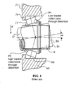
- a conventional gear unit assembly (see Figure 1) comprises a housing wall 11, and a shaft 12 rotatably supported in the housing wall by means of a taper roller bearing 13.
- the taper roller bearing lies axially relative to the shaft at a position aligned with a general plane containing the wall of the housing in the vicinity of the shaft such that radial loads are transmitted directly to the wall of the housing with minimum distortion effects.
- FIG. 2 illustrates a gear unit assembly 20 in accordance with the present invention in which a shaft 21 is rotatably supported in a taper roller bearing 22 at a position, relative to the major axis 23 of the shaft, which is axially displaced from the wall of the housing in the vicinity of the shaft.
- the taper roller bearing is supported in a tubular housing formation defined by a tubular housing sleeve 25 that extends axially inwards to within the chamber 24 of the gear unit housing.
- the axially inner end 26 of the housing sleeve is formed with a radially inwardly extending abutment flange 27 which provides axial location for the outer ring 28 of the taper roller bearing which is mounted in an O configuration in conjunction with the taper roller bearing provided at the other end of the shaft 21.
- the tubular housing sleeve 25 need not be circumferentially continuous, but may comprise an axially extending slot 30 as shown in longitudinal section and end view in Figure 3.
- Figure 3 shows in dotted line 31, in the end direction, the shape adopted by the tubular housing formation 25 when subject to a vertically downwards load F in consequence of a gear unit shaft experiencing loads that cause it to deflect downwards at a position between ends of the shaft.
- the housing sleeve is also able to deflect to the dotted line position 40 and facilitate a reduction in the localised edge stresses that would otherwise be experienced by the bearing rollers.
- a tubular housing formation 50 extends outwards from the gear unit housing, to support a taper roller bearing, in this case one arranged in an X configuration, at a position outwards of the plane 51 defined by the housing wall 52 in the vicinity of the shaft 53.
- Figure 6a shows in section a part of a gear unit housing wall 60 having a housing aperture formation 61 in which the outer ring of a roller bearing (not shown) can be located.
- the formation 61 has an axial length corresponding to the thickness of the wall 60 in the vicinity 62 of the aperture 61 and the thickness of an annular shoulder 63 formed integrally with the material of the wall 60.
- the axial end face 64 of the shoulder 63 is formed with a circumferentially extending groove 65 (see Figure 6b) which, in this embodiment, has a depth slightly less than the thickness of the shoulder 63.
- the aperture 61 is intended to receive a bearing outer ring which has an axial length substantially equal to the axial length of the aperture, and said groove has a depth of 35% of that axial length of the bearing.
- Figure 7 shows views 7a and 7b which correspond substantially with those of Figures 6a and 6b except that in this embodiment a groove 70 is circumferentially discontinuous, and more specifically is of semi-circular shape about the axis of aperture 71.
- Figure 7a shows also the optional use of a rebate to facilitate differential radial stiffness.
- the chamfer line 75 shows a position to which the aperture 71 may be cut back (or initially formed) such that the housing aperture formation is part cylindrical and part frusto-conical in shape.
- the rebate region allows part of the axial length of the outer ring to deform more readily than that part contained within the length of the cylindrical section.
- the present invention is suitable also for use in combination with a grooved type of roller bearing.
Landscapes
- Engineering & Computer Science (AREA)
- General Engineering & Computer Science (AREA)
- Mechanical Engineering (AREA)
- Rolling Contact Bearings (AREA)
- Mounting Of Bearings Or Others (AREA)
- Motor Or Generator Frames (AREA)
- Apparatus For Radiation Diagnosis (AREA)
- Electron Tubes For Measurement (AREA)
- Rolls And Other Rotary Bodies (AREA)
Applications Claiming Priority (3)
| Application Number | Priority Date | Filing Date | Title |
|---|---|---|---|
| GBGB0107615.7A GB0107615D0 (en) | 2001-03-27 | 2001-03-27 | Roller bearing assembly |
| GB0107615 | 2001-03-27 | ||
| PCT/IB2002/002129 WO2002077474A1 (en) | 2001-03-27 | 2002-03-25 | Roller bearing assembly |
Publications (2)
| Publication Number | Publication Date |
|---|---|
| EP1373745A1 EP1373745A1 (en) | 2004-01-02 |
| EP1373745B1 true EP1373745B1 (en) | 2005-09-21 |
Family
ID=9911640
Family Applications (1)
| Application Number | Title | Priority Date | Filing Date |
|---|---|---|---|
| EP02735759A Expired - Lifetime EP1373745B1 (en) | 2001-03-27 | 2002-03-25 | Roller bearing assembly |
Country Status (9)
| Country | Link |
|---|---|
| US (1) | US7429135B2 (da) |
| EP (1) | EP1373745B1 (da) |
| JP (1) | JP4571778B2 (da) |
| AT (1) | ATE305096T1 (da) |
| DE (1) | DE60206250T2 (da) |
| DK (1) | DK1373745T3 (da) |
| ES (1) | ES2248562T3 (da) |
| GB (1) | GB0107615D0 (da) |
| WO (1) | WO2002077474A1 (da) |
Families Citing this family (1)
| Publication number | Priority date | Publication date | Assignee | Title |
|---|---|---|---|---|
| DE102006061258A1 (de) * | 2006-12-22 | 2008-06-26 | Zf Friedrichshafen Ag | Lageranordnung für eine Nebenabtriebswelle |
Family Cites Families (14)
| Publication number | Priority date | Publication date | Assignee | Title |
|---|---|---|---|---|
| DE7831846U1 (de) * | 1979-04-05 | Robert Bosch Gmbh, 7000 Stuttgart | Lagerbuchse für Wälzlager | |
| US1286438A (en) * | 1915-04-21 | 1918-12-03 | A O Smith Company | Roller-bearing. |
| GB1220356A (en) * | 1968-02-01 | 1971-01-27 | Gamet Products Ltd | Improvements in or relating to bearings |
| US4042283A (en) * | 1976-03-05 | 1977-08-16 | Tribotech | Pillow block |
| JPS6139126Y2 (da) * | 1980-03-10 | 1986-11-11 | ||
| US4509804A (en) * | 1983-05-27 | 1985-04-09 | General Motors Corporation | Bearing mount with squeeze film damping |
| GB8708772D0 (en) * | 1987-04-13 | 1987-05-20 | Skf Uk Ltd | Bearing assembly |
| JPH02114502U (da) * | 1989-02-28 | 1990-09-13 | ||
| JP2897782B2 (ja) * | 1990-05-16 | 1999-05-31 | 富士通株式会社 | 低熱歪軸受支持構造 |
| JP2524847Y2 (ja) * | 1991-05-01 | 1997-02-05 | 三菱重工業株式会社 | セラミックス軸受 |
| US5161940A (en) * | 1991-06-21 | 1992-11-10 | Pratt & Whitney Canada, Inc. | Annular support |
| JPH0523767U (ja) * | 1991-08-30 | 1993-03-26 | 株式会社三協精機製作所 | 磁気デイスク駆動用モータ |
| DE9403308U1 (de) * | 1994-02-28 | 1994-04-28 | INA Wälzlager Schaeffler KG, 91074 Herzogenaurach | Ausgleichsgetriebe für ein Kraftfahrzeug |
| FR2738602B1 (fr) * | 1995-09-12 | 1997-11-14 | Aerospatiale | Articulation a centre de rotation et montages d'application de celle-ci |
-
2001
- 2001-03-27 GB GBGB0107615.7A patent/GB0107615D0/en not_active Ceased
-
2002
- 2002-03-25 JP JP2002575492A patent/JP4571778B2/ja not_active Expired - Fee Related
- 2002-03-25 US US10/473,223 patent/US7429135B2/en not_active Expired - Fee Related
- 2002-03-25 ES ES02735759T patent/ES2248562T3/es not_active Expired - Lifetime
- 2002-03-25 EP EP02735759A patent/EP1373745B1/en not_active Expired - Lifetime
- 2002-03-25 WO PCT/IB2002/002129 patent/WO2002077474A1/en not_active Ceased
- 2002-03-25 DK DK02735759T patent/DK1373745T3/da active
- 2002-03-25 DE DE60206250T patent/DE60206250T2/de not_active Expired - Lifetime
- 2002-03-25 AT AT02735759T patent/ATE305096T1/de not_active IP Right Cessation
Also Published As
| Publication number | Publication date |
|---|---|
| DE60206250D1 (de) | 2005-10-27 |
| ATE305096T1 (de) | 2005-10-15 |
| EP1373745A1 (en) | 2004-01-02 |
| GB0107615D0 (en) | 2001-05-16 |
| JP4571778B2 (ja) | 2010-10-27 |
| JP2004522090A (ja) | 2004-07-22 |
| US20040136633A1 (en) | 2004-07-15 |
| DE60206250T2 (de) | 2006-06-08 |
| ES2248562T3 (es) | 2006-03-16 |
| US7429135B2 (en) | 2008-09-30 |
| WO2002077474A1 (en) | 2002-10-03 |
| DK1373745T3 (da) | 2006-01-23 |
Similar Documents
| Publication | Publication Date | Title |
|---|---|---|
| KR100476605B1 (ko) | 압연기 오일 필름 베어링용 슬리브 | |
| US7648280B2 (en) | Weight reduction for journal air bearing | |
| US6106155A (en) | Bearing plate | |
| US9222506B2 (en) | Rolling bearing apparatus | |
| US6830380B2 (en) | Thrust bearing assembly with preload spring | |
| US10859118B2 (en) | Slewing roller bearing with at least two rows of roller elements | |
| US6939052B1 (en) | Bearing with integrated mounting features | |
| JPH0781582B2 (ja) | ころがり軸受の支持体 | |
| EP1373745B1 (en) | Roller bearing assembly | |
| US8596874B2 (en) | Bearing in irregular shaped housings | |
| EP1377754B1 (en) | Method for forming a taper roller bearing assembly | |
| EP3018372B1 (en) | Spacer device, toroidal roller bearing and method | |
| US20040131297A1 (en) | Profiled roller bearing | |
| EP3421828B1 (en) | Roller bearing | |
| US11371558B2 (en) | Roller bearing ring and dismounting procedure | |
| KR20230115985A (ko) | 베어링 장치 | |
| US12196268B2 (en) | Retention assembly for bearing housing assembly | |
| CN111706612A (zh) | 具有圆柱形滚动元件的轴承组件 | |
| EP0750126A1 (en) | Antifriction bearing with seal arrangement | |
| US11815131B2 (en) | Seal assembly with a load bearing ring | |
| JP2025115645A (ja) | ころ軸受 | |
| KR20230129644A (ko) | 구름 베어링 | |
| EP1873411B1 (en) | Roller bearing and bearing structure | |
| KR20180107658A (ko) | 플링거 틸팅 방지용 분리홈이 형성된 베어링용 씰 | |
| JP2001032848A (ja) | 転がり軸受装置 |
Legal Events
| Date | Code | Title | Description |
|---|---|---|---|
| PUAI | Public reference made under article 153(3) epc to a published international application that has entered the european phase |
Free format text: ORIGINAL CODE: 0009012 |
|
| 17P | Request for examination filed |
Effective date: 20031027 |
|
| AK | Designated contracting states |
Kind code of ref document: A1 Designated state(s): AT BE CH CY DE DK ES FI FR GB GR IE IT LI LU MC NL PT SE TR |
|
| AX | Request for extension of the european patent |
Extension state: AL LT LV MK RO SI |
|
| 17Q | First examination report despatched |
Effective date: 20040603 |
|
| GRAP | Despatch of communication of intention to grant a patent |
Free format text: ORIGINAL CODE: EPIDOSNIGR1 |
|
| GRAS | Grant fee paid |
Free format text: ORIGINAL CODE: EPIDOSNIGR3 |
|
| GRAA | (expected) grant |
Free format text: ORIGINAL CODE: 0009210 |
|
| AK | Designated contracting states |
Kind code of ref document: B1 Designated state(s): AT BE CH CY DE DK ES FI FR GB GR IE IT LI LU MC NL PT SE TR |
|
| PG25 | Lapsed in a contracting state [announced via postgrant information from national office to epo] |
Ref country code: IT Free format text: LAPSE BECAUSE OF FAILURE TO SUBMIT A TRANSLATION OF THE DESCRIPTION OR TO PAY THE FEE WITHIN THE PRESCRIBED TIME-LIMIT;WARNING: LAPSES OF ITALIAN PATENTS WITH EFFECTIVE DATE BEFORE 2007 MAY HAVE OCCURRED AT ANY TIME BEFORE 2007. THE CORRECT EFFECTIVE DATE MAY BE DIFFERENT FROM THE ONE RECORDED. Effective date: 20050921 Ref country code: CH Free format text: LAPSE BECAUSE OF FAILURE TO SUBMIT A TRANSLATION OF THE DESCRIPTION OR TO PAY THE FEE WITHIN THE PRESCRIBED TIME-LIMIT Effective date: 20050921 Ref country code: LI Free format text: LAPSE BECAUSE OF FAILURE TO SUBMIT A TRANSLATION OF THE DESCRIPTION OR TO PAY THE FEE WITHIN THE PRESCRIBED TIME-LIMIT Effective date: 20050921 Ref country code: NL Free format text: LAPSE BECAUSE OF FAILURE TO SUBMIT A TRANSLATION OF THE DESCRIPTION OR TO PAY THE FEE WITHIN THE PRESCRIBED TIME-LIMIT Effective date: 20050921 Ref country code: AT Free format text: LAPSE BECAUSE OF FAILURE TO SUBMIT A TRANSLATION OF THE DESCRIPTION OR TO PAY THE FEE WITHIN THE PRESCRIBED TIME-LIMIT Effective date: 20050921 |
|
| REG | Reference to a national code |
Ref country code: GB Ref legal event code: FG4D |
|
| REG | Reference to a national code |
Ref country code: CH Ref legal event code: EP |
|
| REG | Reference to a national code |
Ref country code: IE Ref legal event code: FG4D |
|
| REF | Corresponds to: |
Ref document number: 60206250 Country of ref document: DE Date of ref document: 20051027 Kind code of ref document: P |
|
| PG25 | Lapsed in a contracting state [announced via postgrant information from national office to epo] |
Ref country code: GR Free format text: LAPSE BECAUSE OF FAILURE TO SUBMIT A TRANSLATION OF THE DESCRIPTION OR TO PAY THE FEE WITHIN THE PRESCRIBED TIME-LIMIT Effective date: 20051221 Ref country code: SE Free format text: LAPSE BECAUSE OF FAILURE TO SUBMIT A TRANSLATION OF THE DESCRIPTION OR TO PAY THE FEE WITHIN THE PRESCRIBED TIME-LIMIT Effective date: 20051221 |
|
| REG | Reference to a national code |
Ref country code: DK Ref legal event code: T3 |
|
| PG25 | Lapsed in a contracting state [announced via postgrant information from national office to epo] |
Ref country code: PT Free format text: LAPSE BECAUSE OF FAILURE TO SUBMIT A TRANSLATION OF THE DESCRIPTION OR TO PAY THE FEE WITHIN THE PRESCRIBED TIME-LIMIT Effective date: 20060221 |
|
| NLV1 | Nl: lapsed or annulled due to failure to fulfill the requirements of art. 29p and 29m of the patents act | ||
| REG | Reference to a national code |
Ref country code: ES Ref legal event code: FG2A Ref document number: 2248562 Country of ref document: ES Kind code of ref document: T3 |
|
| PG25 | Lapsed in a contracting state [announced via postgrant information from national office to epo] |
Ref country code: IE Free format text: LAPSE BECAUSE OF NON-PAYMENT OF DUE FEES Effective date: 20060327 |
|
| PG25 | Lapsed in a contracting state [announced via postgrant information from national office to epo] |
Ref country code: MC Free format text: LAPSE BECAUSE OF NON-PAYMENT OF DUE FEES Effective date: 20060331 Ref country code: LU Free format text: LAPSE BECAUSE OF NON-PAYMENT OF DUE FEES Effective date: 20060331 |
|
| REG | Reference to a national code |
Ref country code: CH Ref legal event code: PL |
|
| ET | Fr: translation filed | ||
| PLBE | No opposition filed within time limit |
Free format text: ORIGINAL CODE: 0009261 |
|
| STAA | Information on the status of an ep patent application or granted ep patent |
Free format text: STATUS: NO OPPOSITION FILED WITHIN TIME LIMIT |
|
| 26N | No opposition filed |
Effective date: 20060622 |
|
| REG | Reference to a national code |
Ref country code: IE Ref legal event code: MM4A |
|
| PG25 | Lapsed in a contracting state [announced via postgrant information from national office to epo] |
Ref country code: TR Free format text: LAPSE BECAUSE OF FAILURE TO SUBMIT A TRANSLATION OF THE DESCRIPTION OR TO PAY THE FEE WITHIN THE PRESCRIBED TIME-LIMIT Effective date: 20050921 |
|
| PG25 | Lapsed in a contracting state [announced via postgrant information from national office to epo] |
Ref country code: CY Free format text: LAPSE BECAUSE OF FAILURE TO SUBMIT A TRANSLATION OF THE DESCRIPTION OR TO PAY THE FEE WITHIN THE PRESCRIBED TIME-LIMIT Effective date: 20050921 |
|
| REG | Reference to a national code |
Ref country code: GB Ref legal event code: 732E Free format text: REGISTERED BETWEEN 20110224 AND 20110302 |
|
| REG | Reference to a national code |
Ref country code: FR Ref legal event code: TP |
|
| REG | Reference to a national code |
Ref country code: DE Ref legal event code: R081 Ref document number: 60206250 Country of ref document: DE Owner name: HANSEN INDUSTRIAL TRANSMISSIONS N.V., BE Free format text: FORMER OWNER: HANSEN TRANSMISSIONS INTERNATIONAL N.V., EDEGEM, BE Effective date: 20110513 |
|
| REG | Reference to a national code |
Ref country code: ES Ref legal event code: PC2A Owner name: HANSEN INDUSTRIAL TRANSMISSIONS, N.V. Effective date: 20110908 |
|
| PGFP | Annual fee paid to national office [announced via postgrant information from national office to epo] |
Ref country code: ES Payment date: 20130305 Year of fee payment: 12 Ref country code: DE Payment date: 20130221 Year of fee payment: 12 Ref country code: DK Payment date: 20130222 Year of fee payment: 12 Ref country code: GB Payment date: 20130228 Year of fee payment: 12 Ref country code: FI Payment date: 20130222 Year of fee payment: 12 |
|
| PGFP | Annual fee paid to national office [announced via postgrant information from national office to epo] |
Ref country code: BE Payment date: 20130222 Year of fee payment: 12 |
|
| PGFP | Annual fee paid to national office [announced via postgrant information from national office to epo] |
Ref country code: FR Payment date: 20130429 Year of fee payment: 12 |
|
| REG | Reference to a national code |
Ref country code: DE Ref legal event code: R119 Ref document number: 60206250 Country of ref document: DE |
|
| REG | Reference to a national code |
Ref country code: DK Ref legal event code: EBP Effective date: 20140331 |
|
| PG25 | Lapsed in a contracting state [announced via postgrant information from national office to epo] |
Ref country code: FI Free format text: LAPSE BECAUSE OF NON-PAYMENT OF DUE FEES Effective date: 20140325 |
|
| GBPC | Gb: european patent ceased through non-payment of renewal fee |
Effective date: 20140325 |
|
| REG | Reference to a national code |
Ref country code: FR Ref legal event code: ST Effective date: 20141128 |
|
| REG | Reference to a national code |
Ref country code: DE Ref legal event code: R119 Ref document number: 60206250 Country of ref document: DE Effective date: 20141001 |
|
| PG25 | Lapsed in a contracting state [announced via postgrant information from national office to epo] |
Ref country code: DE Free format text: LAPSE BECAUSE OF NON-PAYMENT OF DUE FEES Effective date: 20141001 Ref country code: FR Free format text: LAPSE BECAUSE OF NON-PAYMENT OF DUE FEES Effective date: 20140331 Ref country code: GB Free format text: LAPSE BECAUSE OF NON-PAYMENT OF DUE FEES Effective date: 20140325 |
|
| REG | Reference to a national code |
Ref country code: ES Ref legal event code: FD2A Effective date: 20150424 |
|
| PG25 | Lapsed in a contracting state [announced via postgrant information from national office to epo] |
Ref country code: DK Free format text: LAPSE BECAUSE OF NON-PAYMENT OF DUE FEES Effective date: 20140331 |
|
| PG25 | Lapsed in a contracting state [announced via postgrant information from national office to epo] |
Ref country code: ES Free format text: LAPSE BECAUSE OF NON-PAYMENT OF DUE FEES Effective date: 20140326 |
|
| PG25 | Lapsed in a contracting state [announced via postgrant information from national office to epo] |
Ref country code: BE Free format text: LAPSE BECAUSE OF NON-PAYMENT OF DUE FEES Effective date: 20140331 |