EP1373796B1 - Chaudieres a vapeur sous pression et leur commande - Google Patents
Chaudieres a vapeur sous pression et leur commande Download PDFInfo
- Publication number
- EP1373796B1 EP1373796B1 EP02720166A EP02720166A EP1373796B1 EP 1373796 B1 EP1373796 B1 EP 1373796B1 EP 02720166 A EP02720166 A EP 02720166A EP 02720166 A EP02720166 A EP 02720166A EP 1373796 B1 EP1373796 B1 EP 1373796B1
- Authority
- EP
- European Patent Office
- Prior art keywords
- boiler
- steam
- burner
- water
- temperature
- Prior art date
- Legal status (The legal status is an assumption and is not a legal conclusion. Google has not performed a legal analysis and makes no representation as to the accuracy of the status listed.)
- Expired - Lifetime
Links
- XLYOFNOQVPJJNP-UHFFFAOYSA-N water Substances O XLYOFNOQVPJJNP-UHFFFAOYSA-N 0.000 claims abstract description 86
- 238000000034 method Methods 0.000 claims abstract description 18
- 239000000446 fuel Substances 0.000 claims description 23
- 238000002485 combustion reaction Methods 0.000 claims description 19
- 239000007789 gas Substances 0.000 claims description 16
- 238000012545 processing Methods 0.000 claims description 6
- 230000008569 process Effects 0.000 claims description 5
- 239000000203 mixture Substances 0.000 claims description 4
- 239000008236 heating water Substances 0.000 claims description 2
- 238000010304 firing Methods 0.000 abstract description 9
- 238000012544 monitoring process Methods 0.000 abstract description 4
- 239000000523 sample Substances 0.000 description 45
- 230000000712 assembly Effects 0.000 description 14
- 238000000429 assembly Methods 0.000 description 14
- 230000008859 change Effects 0.000 description 6
- 238000005259 measurement Methods 0.000 description 4
- 230000001419 dependent effect Effects 0.000 description 2
- 238000010586 diagram Methods 0.000 description 2
- 239000003989 dielectric material Substances 0.000 description 2
- 238000004868 gas analysis Methods 0.000 description 2
- 239000004810 polytetrafluoroethylene Substances 0.000 description 2
- 230000005855 radiation Effects 0.000 description 2
- 230000009467 reduction Effects 0.000 description 2
- 230000004044 response Effects 0.000 description 2
- UGFAIRIUMAVXCW-UHFFFAOYSA-N Carbon monoxide Chemical compound [O+]#[C-] UGFAIRIUMAVXCW-UHFFFAOYSA-N 0.000 description 1
- 229910000831 Steel Inorganic materials 0.000 description 1
- 238000004458 analytical method Methods 0.000 description 1
- 230000008901 benefit Effects 0.000 description 1
- 238000009835 boiling Methods 0.000 description 1
- 238000006243 chemical reaction Methods 0.000 description 1
- 230000007423 decrease Effects 0.000 description 1
- 238000013461 design Methods 0.000 description 1
- 238000001514 detection method Methods 0.000 description 1
- 239000003546 flue gas Substances 0.000 description 1
- -1 polytetra-fluoroethylene Polymers 0.000 description 1
- 229940058401 polytetrafluoroethylene Drugs 0.000 description 1
- 229920001343 polytetrafluoroethylene Polymers 0.000 description 1
- 238000005070 sampling Methods 0.000 description 1
- 239000010959 steel Substances 0.000 description 1
- 230000001052 transient effect Effects 0.000 description 1
Images


Classifications
-
- F—MECHANICAL ENGINEERING; LIGHTING; HEATING; WEAPONS; BLASTING
- F22—STEAM GENERATION
- F22B—METHODS OF STEAM GENERATION; STEAM BOILERS
- F22B37/00—Component parts or details of steam boilers
- F22B37/78—Adaptations or mounting of level indicators
-
- F—MECHANICAL ENGINEERING; LIGHTING; HEATING; WEAPONS; BLASTING
- F22—STEAM GENERATION
- F22D—PREHEATING, OR ACCUMULATING PREHEATED, FEED-WATER FOR STEAM GENERATION; FEED-WATER SUPPLY FOR STEAM GENERATION; CONTROLLING WATER LEVEL FOR STEAM GENERATION; AUXILIARY DEVICES FOR PROMOTING WATER CIRCULATION WITHIN STEAM BOILERS
- F22D5/00—Controlling water feed or water level; Automatic water feeding or water-level regulators
- F22D5/26—Automatic feed-control systems
- F22D5/30—Automatic feed-control systems responsive to both water level and amount of steam withdrawn or steam pressure
Definitions
- the invention relates to pressurised steam boilers and their control, in particular to to a method and apparatus for assessing the mass flow of steam from a steam boiler.
- a method of assessing in a control unit the mass flow of steam from the boiler by processing of input signals including ones enabling assessments to be made of:
- variable itself may not be directly sensed but rather one or more other variables, from which the variable being monitored can be calculated, may be sensed.
- the firing rate of the burner need not be directly sensed and the pressure of the water in the boiler may be sensed to indicate the pressure of the steam.
- Variables measured to assess the heat generated by combustion in the burner may include the rate of feeding of fuel to the burner, and/or the composition of the combustion products.
- Variables measured to assess the heat dissipated other than in the steam may include the temperature of the combustion products and/or the rate of feeding fuel to the burner.
- a fuel burner control system which includes flue gas sampling and analysing apparatus and which also includes a burner controller which is the subject of GB 2138610A. That control system already receives inputs relating to the rate of feeding fuel to the burner, the composition of the exhaust gases and the temperature of the exhaust gases. Furthermore it is common for a pressurised steam boiler control system to include sensors for measuring the temperature and pressure of the steam generated by the boiler. Thus it can be seen that all the variables required for the assessment of the mass flow of steam from the boiler may already be available without any extra sensors being required. If desired, however, one or more extra sensors may be provided. For example, a sensor for measuring the temperature of the water being fed into the boiler may be provided.
- the assessment of the mass flow of steam from the boiler may be used only as a measure of the flow at a moment in time, or it may also or alternatively be used to provide an assessment of the aggregate amount of steam generated over a certain extended period of time. In the latter case, it may be necessary to allow for other losses within the system, when making the assessment, for example it may be appropriate to assume that a certain percentage of heat is lost during blow down of a boiler. For example an overall loss of 6 per cent might be allowed for.
- the present invention still further provides a pressurised steam boiler including:
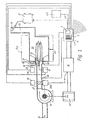
- a burner 20 having a burner head 21, a combustion chamber 22 and a duct 23 for combustion products which comprise exhaust gases.
- the duct 23 passes through a pressurized steam boiler; thereafter the exhaust gases are vented through a flue.
- Air is fed to the burner head 21 from an air inlet 24, through a centrifugal fan 26 and then through an outlet damper 27.
- the burner head 21 is able to operate with either gas or oil as the fuel; gas is fed to the burner head from an inlet 28 via a valve 29 whilst oil is fed to the burner head from an inlet 30 via a valve 31.
- a control unit 1 is provided for controlling the operation of the burner and boiler.
- the control unit 1 has a display 2, a proximity sensor 3 for detecting that a person is nearby, and a set of keys 5 enabling an operator to enter instructions to the control unit.
- the purpose of the proximity sensor is not relevant to the present invention and will not be described further herein; its purpose is described in GB2335736A.
- the control unit 1 is connected to various sensing devices and drive devices, as shown in the drawing. More particularly the unit is connected via an exhaust gas analyser 37 to an exhaust gas analysis probe 38 (which includes a temperature sensor), and to a flame detection unit 40 at the burner head.
- the control unit 1 is also connected via an inverter interface unit 41 and an inverter 42 to the motor of the fan 26 (with interface unit 41 receiving a feed back signal from a tachometer 26A associated with the fan 26), via an air servo motor 44 to the air outlet damper 27, to an air pressure sensing device 45 provided in the air supply duct downstream of the outlet damper 27, via fuel servo motors 46 to the fuel valves 29, 31 and to a further servo motor 47 for adjusting the configuration of the burner head 21.
- control unit 1 The connections described above relate to the control of the burner 20 by the control unit 1.
- the control unit 1 is, however, also connected, via an RS485 link 48 to a further controller 49, which is shown in Fig 2 and whose functions are described below.
- the combustion chamber 22 of the burner 20 is arranged inside a boiler 50 in a conventional manner.
- the boiler 50 is shown schematically in chain dotted outline.
- Fig 1 suggests that the combustion chamber leads directly to the exhaust duct 23, it will be understood by those skilled in the art that in practice the gaseous products of combustion follow a serpentine path passing through the boiler 50 a few times before reaching the exhaust duct 23 and being exhausted to atmosphere.
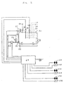
- Fig 2 provides a schematic representation of the boiler and shows a boiler housing 51 which in normal use is filled to approximately the height shown by dotted line L1 in Fig 2. It will be appreciated that the combustion chamber and ducting for the exhaust gases are not shown in Fig 2.
- a water pipe 52 feeds water into the bottom of the boiler at a rate determined by settings of a variable speed pump 53 and via a motorized control valve 54.
- a temperature detector 59 senses the temperature of the water as it enters the boiler.
- a steam outlet pipe 55 takes steam under pressure from the top of the boiler 51.
- the pressure of the steam taken from the boiler housing 51 is sensed by a pressure detector 56 while its temperature is sensed by a temperature detector 57.
- Mounted in the top of the boiler housing 51 are a pair of capacitance probe assemblies 58A and 58B.
- the capacitance probe assemblies are identical to one another and one is described below with reference to Figs 3 and 4.
- the further controller 49 receives input signals from the following (excluding the connection via the RS485 link 48 to the control unit 1):
- a signal from the pressure detector 56 is passed back along a line 60 (not shown in Fig 1) to the control unit 1 where it provides an input signal representing demand to the control unit.
- the further controller 49 provides output signals to the following (excluding the connection via the RS485 link 48 to the control unit 1):
- warning light and audible alarms may be varied from one application to another according to what is required.
- the dotted line L1 indicates the centre of the normal operating range of water level in the boiler. Also shown is a dotted line L2 marking the "first low”, a dotted line L3 marking the "second low” and a dotted line L4 marking the high water level.
- each capacitance probe assembly 58A, 58B includes a main body 70 and an elongate probe 71 which projects downwardly into the interior of the boiler and extends through the high water level (L4), the normal operating level (L1), the "first low” (L2) and the “second low” (L3).
- L4 high water level
- L1 normal operating level
- L2 first low
- L3 second low
- the probes 71 are manufactured in various lengths and an appropriate length of probe is chosen for each boiler.
- the probes may be available in lengths of about 0.5m, 1.0m and 1.5m.
- Each probe 71 is formed from a central steel bar 72 surrounded by a sleeve 73 of dielectric material. Also a plug 74 of dielectric material is provided at the free end of the sleeve 73 to seal that end of the probe.
- the probe 71 forms together with the medium surrounding the sleeve 73 a variable capacitance. Since the capacitance is very dependent on whether the medium is water or steam the value of the capacitance is dependent upon how great a length of the probe is surrounded by water rather than steam. Thus, the capacitance of the probe provides an indication of the level of water in the boiler, for all levels between, and including, L3 and L4.
- a printed circuit board 75 is mounted in an enlarged rear portion 76 of the main body 70, the board 75 carrying the necessary processing circuitry, which is shown in block diagram form in Fig 4.
- Fig 4 there is shown the probe 71 marked as a varying capacitance, a reference capacitance 77, a relay 78 for alternately connecting the probe 71 and the reference capacitance in the circuit, an oscillator 79, a processor 80 which both controls the operation of the relay 78 and together with the oscillator 79 is able to provide a measure of the capacitance being sensed by detecting the frequency of a signal in a circuit incorporating the capacitance, and a driver 81 which transmits a signal from the probe assembly to the further controller 49.
- the connection between each probe assembly 58A, 58B and the further controller 49 is made via RS485 links.
- the probe capacitance varies from 10pF to 200pf
- the reference capacitance 77 is 120pF
- the oscillator 79 is a 555 Type Oscillator
- the processor 80 is an 80188 processor
- the sleeve 73 is 12mm outside diameter, 6mm inside diameter and is made of PTFE (polytetra-fluoroethylene).
- the frequency of the output from the probe assembly alters; typically, the frequency output is of the order of 45,000 Hz and a change of 1mm in water level alters the frequency by 20 Hz.
- the capacitance of each probe 71 is measured alternately with the reference capacitance 77 of that probe.
- the controller 49 reads signals from each of the probe assemblies 58A, 58B alternately, although, if preferred, simultaneous readings may be obtained.
- the water is somewhat turbulent at least near the surface and that is liable to give rise to some inaccuracy in the measurement made.
- controller 49 is arranged to allow for some discrepancy in the signals from the probe assemblies 58A, 58B, but apart from that checks both that the signal of the reference capacitance indicates the correct value of capacitance and that each of the probes 71 indicates the same value of capacitance and therefore the same water level.
- One particular way in which turbulence in the water can be allowed for and indeed even taken advantage of is described later.
- GB2138610A and GB2169726A both provide further details of the normal operation of the burner.
- the boiler operates in a conventional manner when the water level is normal and, via the controller 49, feeds back signals, for example indicating a dropping steam temperature, to the control unit 1.
- the controller 49 is programmed to adjust the speed of the pump 53 at the water inlet to allow more water into the boiler; similarly, in the event that the water level in the boiler rises gradually a little above the average normal level, then the controller 49 is programmed to close the control valve 54 or reduce the speed of the pump 53 at the water inlet to allow less water into the boiler. In either case, however, the operation of the burner 20 is not affected because the output signals from the control unit 1 are not altered.
- the controller 49 reacts in various ways: firstly the warning light 61A and audible alarm 61B are actuated; secondly a signal is passed back via the RS485 link 48 to the control unit 1 which then shuts down the burner 20 by turning off the supplies of fuel and air to the burner head 21; thirdly, the inlet flow of water into the boiler 5 is increased by adjustment of the control valve 54 and/or the pump 53.
- the controller 49 can reverse the measures described in the paragraph immediately above. If for some reason, however, the water level continues to fall, for example because the water inlet is blocked, then when it reaches the level L3 in Fig 2 the warning light 62A and the audible alarm 62B are activated and a further control signal sent from the controller 49 to the control unit 1, preventing the burner from being turned back on without manual intervention by an operator.
- the controller 49 reacts in various ways: firstly the warning light 63A and the audible alarm 63B are activated; secondly a signal is passed back via the RS485 link 48 to the control unit 1 which then shuts down the burner 20 by turning off the supplies of fuel and air to the burner head; thirdly, the inlet flow of water into the boiler 5 is stopped by adjustment of the control valve 54 and/or the pump 53.
- the reaction to an increasing water level is determined by assessing within the control system also how the steam pressure in the boiler, which is measured by the detector 56, is changing and how the firing rate of the burner 20, which can for example be assessed from the information in the control unit 1 of the amount of fuel being fed to the burner, is changing.
- the variables of water level, steam pressure and firing rate can each be sensed at one second intervals and their movements over the last twenty seconds used to assess the cause of an increase in water level.
- the controller 49 acts to reduce at a slow rate the amount of water per unit time entering the boiler through the pipe 52.
- the controller 49 may act to maintain, at its current rate, or to increase the amount of water per unit time entering the boiler through the pipe 52.
- control criteria that are applied can be varied by the designer of the control system and/or by the commissioning engineer who installs the control system.
- the system may be arranged so that, if only one probe assembly detects a water level beyond an acceptable range, the alarm and/or burner shut down procedure is commenced only after a relatively long period, for example 20 seconds, whereas, if both probe assemblies detect a water level beyond an acceptable range, the alarm and/or burner shut down procedure is commenced sooner, for example after 10 seconds.
- a relatively long period for example 20 seconds
- both probe assemblies detect a water level beyond an acceptable range
- the alarm and/or burner shut down procedure is commenced sooner, for example after 10 seconds.
- the controller 49 reads a water level signal from each of the probe assemblies 58A, 58B every tenth of a second. To form a water level signal the highest and lowest values are taken from ten consecutive readings from a probe and one tenth of the difference between the values is added to the lowest value to define what is then regarded as the value for that probe. The same procedure is carried out for the other probe and the two values so obtained averaged to provide a good measurement of water level even when the water is turbulent.
- a characteristic of a typical wave in a boiler is that peaks of the wave are significantly narrower than troughs; for that reason and because of other forms of turbulence, the peaks in the turbulent water contain relatively little water.
- a water level reading is generated every second; that reading may itself then advantageously be combined with, say, nine other similar readings to provide an average reading that covers a ten second period. That average reading may be updated at any selected rate down to once per second.
- the readings from each probe are also used in this particularly advantageous embodiment to detect turbulence.
- the probe assemblies 58A, 58B can be expected to give readings with short term variations when there is turbulence; more particularly the readings can be expected to fluctuate considerably over a period of a second when there is turbulence.
- the control system already described is knowledgeable of the pressure in the boiler and the water temperature and therefore knows whether or not the water should be boiling and therefore turbulent. Changes in water level of 2.5mm or more in the course of one second may be regarded as indicative of turbulence and thus it is possible to arrange for the control system to conduct a further check that the probe assemblies 58A and 58B are operating properly. In the event of a conflict between the inputs, an alarm may be sounded and/or the burner 20 turned off.
- the system may be arranged to allow for a disparity in water level readings from the respective probe assemblies of up to 50mm for up to 20 seconds.
- the control system described above is also able to assess the amount of steam per unit time that is leaving the boiler and, therefore, can dispose with the need for one or more steam flow meters.
- the assessment is accomplished by assessing all the energy input per unit time into the burner and boiler and the energy output per unit time other than in the steam.
- the difference between the energy input and the energy output as so assessed is of course a measure of the energy that has been put into the water/steam in the boiler.
- Provided the approximate temperature of the water passed into the system is known and the temperature and pressure of the steam are also known it becomes possible to calculate the mass flow rate of the steam.
- the accuracy with which the energy inputs and outputs are assessed is a matter of design choice, but one particular example is given below.
- the energy input to the system is regarded as consisting exclusively of the heat generated from combustion of the fuel in the burner 20.
- the control unit 1 is able to compute the amount of fuel being combusted and, if desired, can also take into account the exhaust gas analysis results from the analyser 37 to arrive at the rate of energy input at any one time.
- a calibrated fuel meter may be used in order that the control unit 1 is able to store a value of the fuel flow rate and/or heat energy input corresponding to each of a plurality of settings of the fuel valve. The control unit 1 is then able to arrive at appropriate values for any intermediate settings by interpolation.
- the energy outputs from the system, apart from the steam are regarded as comprising the following:
- the control unit 1 is informed of the temperature of the exhaust gases from the exhaust gas analyser 37 and is able to compute the flow rate of exhaust gases from the amounts of fuel and/or air being fed to the burner. For the losses from the burner and boiler, it is assumed that a fixed percentage of the heat input (in a particular example 0.25%) is lost when the burner is running at maximum firing rate and that the amount of heat lost remains the same at lower firing rates so that if the burner is turned down to, for example, one quarter of its maximum firing rate the percentage loss increases fourfold (in the particular example to 1%).
- control unit 1 is able to assess the energy input into the water in the boiler. From the controller 49 the temperature of the water fed into the boiler is known and the temperature and pressure of the steam leaving the boiler are also known. The heat required to heat water (specific heat) to convert water to steam (latent heat) and to bring steam to a certain temperature and pressure is of course all well established and therefore the data available from the controller 49 when taken with that from the control unit 1 enables the new flow rate of the steam to be computed.
- control unit 1 and the controller 49 are separate physical units; it is, however, possible to locate the controller 49 within the control unit 1 and indeed, if desired, the controller 49 may be integrated wholly into the control unit 1, so that for example they share the same microprocessor.
Landscapes
- Engineering & Computer Science (AREA)
- Physics & Mathematics (AREA)
- Thermal Sciences (AREA)
- Mechanical Engineering (AREA)
- General Engineering & Computer Science (AREA)
- Control Of Steam Boilers And Waste-Gas Boilers (AREA)
- Engine Equipment That Uses Special Cycles (AREA)
- Irons (AREA)
- Air Bags (AREA)
- Switches With Compound Operations (AREA)
- Regulation And Control Of Combustion (AREA)
Claims (6)
- Procédé d'évaluation, dans une unité de commande (1), du débit massique de la vapeur issue d'une chaudière à vapeur sous pression en traitant des signaux d'entrée, y compris des signaux permettant d'exécuter des évaluations de :dans lequel les variables mesurées pour évaluer la chaleur dissipée autrement que dans la vapeur comprennent la température des produits de combustion, et les signaux d'entrée qui sont traités pour évaluer le débit massique de la vapeur issue de la chaudière (50) comprennent un signal représentant la température de l'eau introduite dans la chaudière (50).a) la chaleur générée par la combustion dans le brûleur (20)b) la température et la pression de la vapeur générée par la chaudière (50)c) la chaleur dissipée autrement que dans la vapeur,
- Procédé selon la revendication 1, dans lequel les variables mesurées pour évaluer la chaleur générée par combustion dans le brûleur (20) comprennent la vitesse d'introduction du combustible vers le brûleur (20).
- Procédé selon la revendication 1 ou 2, dans lequel les variables mesurées pour évaluer la chaleur générée par combustion dans le brûleur (20) comprennent la composition des produits de combustion.
- Procédé selon l'une quelconque des revendications 1 à 3, dans lequel les variables mesurées pour évaluer la chaleur dissipée autrement que dans la vapeur comprennent la vitesse d'introduction du combustible vers le brûleur (20).
- Chaudière à vapeur sous pression comprenant :un corps de chaudière (51) pour contenir l'eau dans la chaudière,un brûleur (20) pour chauffer l'eau dans la chaudière (50) et convertir l'eau en vapeur,un détecteur ou capteur de pression (56) pour détecter la pression de la vapeur dans la chaudière,un détecteur ou capteur de température (57) pour détecter la température de la vapeur dans la chaudière,un détecteur ou capteur de débit de combustible pour mesurer le débit du combustible dans le brûleur,un autre détecteur ou capteur de température pour détecter la température des gaz d'échappement,une unité de commande (1) pour recevoir et traiter les signaux d'entrée issus de tous lesdits détecteurs et pour évaluer indirectement le débit massique de la vapeur issue de la chaudière, la chaudière comprenant également encore un autre détecteur ou capteur de température pour détecter la température de l'eau à une entrée de la chaudière (50), l'unité de commande (1) étant disposée de façon à recevoir et à traiter également un signal d'entrée issu de l'autre encore détecteur de température, afin d'évaluer indirectement le débit massique de la vapeur issue de la chaudière.
- Chaudière à vapeur sous pression selon la revendication 5, comprenant en outre un détecteur ou capteur (38) de gaz d'échappement pour analyser la composition des produits de combustion, l'unité de commande (1) étant disposée pour recevoir et traiter également un signal d'entrée issu du détecteur de gaz d'échappement (38), afin d'évaluer indirectement le débit massique de la vapeur issue de la chaudière.
Priority Applications (3)
| Application Number | Priority Date | Filing Date | Title |
|---|---|---|---|
| EP03023290A EP1384946B1 (fr) | 2001-04-02 | 2002-04-02 | Chaudières à vapeur sous pression et leur commande |
| EP03023289A EP1384944B1 (fr) | 2001-04-02 | 2002-04-02 | Chaudières à vapeur sous pression et leur commande |
| EP03023291A EP1384945B1 (fr) | 2001-04-02 | 2002-04-02 | Chaudières à vapeur sous pression et leur commande |
Applications Claiming Priority (3)
| Application Number | Priority Date | Filing Date | Title |
|---|---|---|---|
| GB0108229A GB2374135A (en) | 2001-04-02 | 2001-04-02 | Pressurised steam boilers and their control |
| GB0108229 | 2001-04-02 | ||
| PCT/GB2002/001547 WO2002079695A2 (fr) | 2001-04-02 | 2002-04-02 | Chaudieres a vapeur sous pression et leur commande |
Related Child Applications (3)
| Application Number | Title | Priority Date | Filing Date |
|---|---|---|---|
| EP03023290A Division EP1384946B1 (fr) | 2001-04-02 | 2002-04-02 | Chaudières à vapeur sous pression et leur commande |
| EP03023291A Division EP1384945B1 (fr) | 2001-04-02 | 2002-04-02 | Chaudières à vapeur sous pression et leur commande |
| EP03023289A Division EP1384944B1 (fr) | 2001-04-02 | 2002-04-02 | Chaudières à vapeur sous pression et leur commande |
Publications (2)
| Publication Number | Publication Date |
|---|---|
| EP1373796A2 EP1373796A2 (fr) | 2004-01-02 |
| EP1373796B1 true EP1373796B1 (fr) | 2005-02-02 |
Family
ID=9912084
Family Applications (4)
| Application Number | Title | Priority Date | Filing Date |
|---|---|---|---|
| EP03023289A Expired - Lifetime EP1384944B1 (fr) | 2001-04-02 | 2002-04-02 | Chaudières à vapeur sous pression et leur commande |
| EP02720166A Expired - Lifetime EP1373796B1 (fr) | 2001-04-02 | 2002-04-02 | Chaudieres a vapeur sous pression et leur commande |
| EP03023291A Expired - Lifetime EP1384945B1 (fr) | 2001-04-02 | 2002-04-02 | Chaudières à vapeur sous pression et leur commande |
| EP03023290A Expired - Lifetime EP1384946B1 (fr) | 2001-04-02 | 2002-04-02 | Chaudières à vapeur sous pression et leur commande |
Family Applications Before (1)
| Application Number | Title | Priority Date | Filing Date |
|---|---|---|---|
| EP03023289A Expired - Lifetime EP1384944B1 (fr) | 2001-04-02 | 2002-04-02 | Chaudières à vapeur sous pression et leur commande |
Family Applications After (2)
| Application Number | Title | Priority Date | Filing Date |
|---|---|---|---|
| EP03023291A Expired - Lifetime EP1384945B1 (fr) | 2001-04-02 | 2002-04-02 | Chaudières à vapeur sous pression et leur commande |
| EP03023290A Expired - Lifetime EP1384946B1 (fr) | 2001-04-02 | 2002-04-02 | Chaudières à vapeur sous pression et leur commande |
Country Status (7)
| Country | Link |
|---|---|
| US (1) | US7249573B2 (fr) |
| EP (4) | EP1384944B1 (fr) |
| AT (4) | ATE289669T1 (fr) |
| AU (1) | AU2002251236A1 (fr) |
| DE (4) | DE60203002T2 (fr) |
| GB (1) | GB2374135A (fr) |
| WO (1) | WO2002079695A2 (fr) |
Families Citing this family (27)
| Publication number | Priority date | Publication date | Assignee | Title |
|---|---|---|---|---|
| GB2374135A (en) | 2001-04-02 | 2002-10-09 | Autoflame Eng Ltd | Pressurised steam boilers and their control |
| US7819334B2 (en) * | 2004-03-25 | 2010-10-26 | Honeywell International Inc. | Multi-stage boiler staging and modulation control methods and controllers |
| GB0408102D0 (en) | 2004-04-08 | 2004-05-12 | Autoflame Eng Ltd | Total dissolved solids |
| GB2418724A (en) * | 2004-09-30 | 2006-04-05 | Energy Control Systems Ltd | Boiler control unit |
| US7425834B2 (en) * | 2005-08-26 | 2008-09-16 | Power Integrations, Inc. | Method and apparatus to select a parameter/mode based on a time measurement |
| DE102006015771A1 (de) * | 2006-04-04 | 2007-10-11 | J. Eberspächer GmbH & Co. KG | Verfahren zum Betreiben eines brennstoffbetriebenen Fahrzeugheizgerätes |
| US9863646B2 (en) * | 2007-01-26 | 2018-01-09 | David E. Johnson, Jr. | Modulation control of hydronic systems |
| EP2065641A3 (fr) * | 2007-11-28 | 2010-06-09 | Siemens Aktiengesellschaft | Procédé de fonctionnement d'un générateur de vapeur en flux continu, ainsi que générateur de vapeur en flux à sens unique |
| US20090145218A1 (en) * | 2007-12-07 | 2009-06-11 | Bulldog Boiler Rentals, Ltd. | Fluid level sensing assembly and method for configuring same |
| US20090197212A1 (en) * | 2008-02-04 | 2009-08-06 | Maxitrol Company | Premix Burner Control System and Method |
| EP2119880A1 (fr) * | 2008-02-15 | 2009-11-18 | Siemens Aktiengesellschaft | Procédé destiné à démarrer une chaudière à vapeur |
| KR100985384B1 (ko) * | 2008-06-27 | 2010-10-05 | 주식회사 경동네트웍 | 온수 공급 시스템에서 저유량의 온수 사용시 온수 온도를제어하기 위한 방법 |
| US8116106B2 (en) | 2008-09-19 | 2012-02-14 | Power Integrations, Inc. | Method and apparatus to select a parameter/mode based on a measurement during an initialization period |
| DE102008042274A1 (de) * | 2008-09-22 | 2010-04-08 | BSH Bosch und Siemens Hausgeräte GmbH | Dampfkessel für ein Haushaltsgerät mit einem befüllbaren Dampfkessel und Verfahren zum Betreiben eines Dampfkessels |
| US8469050B2 (en) * | 2008-11-07 | 2013-06-25 | Abbott Medical Optics Inc. | Capacitive fluid level sensing |
| US8757105B2 (en) * | 2008-12-08 | 2014-06-24 | General Electric Company | System and method for controlling liquid level in a vessel |
| GB0901284D0 (en) * | 2009-01-26 | 2009-03-11 | Autoflame Eng Ltd | Burner operation and installation |
| US9017156B2 (en) * | 2009-10-30 | 2015-04-28 | Mestek, Inc. | Air control module |
| GB2484957A (en) * | 2010-10-28 | 2012-05-02 | Autoflame Eng Ltd | Burner control with stored values for valve settings and pressures |
| DE102011084906A1 (de) * | 2011-10-20 | 2013-04-25 | Endress+Hauser Meßtechnik GmbH+Co.KG | Verfahren zur Überwachung einer Pumpe für Flüssigkeiten und Pumpe |
| US10429063B2 (en) | 2016-01-27 | 2019-10-01 | Fluid Handling Llc | Smart algorithm to determine “steam boiler water condition” |
| CN108224401A (zh) * | 2018-03-14 | 2018-06-29 | 华北电力大学 | 超临界水防烧干系统装置 |
| CN108679593A (zh) * | 2018-07-03 | 2018-10-19 | 南京曼可新材料有限公司 | 一种锅炉运行监测装置及系统 |
| CN109813400B (zh) * | 2019-03-23 | 2024-02-06 | 重庆市计量质量检测研究院 | 基于物联网技术的锅炉主蒸汽流量计在线校核测试系统 |
| CN111380592A (zh) * | 2020-04-07 | 2020-07-07 | 奥普家居股份有限公司 | 水盒水位检测装置、检测方法及集成灶 |
| CN113984129B (zh) * | 2021-12-27 | 2022-03-22 | 常州艾肯智造科技有限公司 | 蒸汽系统用智能化在线数据采集传输系统及方法 |
| CN115468184B (zh) * | 2022-09-05 | 2024-07-12 | 哈尔滨森泰克再生能源技术开发有限公司 | 一种锅炉供热监测装置 |
Family Cites Families (33)
| Publication number | Priority date | Publication date | Assignee | Title |
|---|---|---|---|---|
| US3042007A (en) * | 1958-07-28 | 1962-07-03 | Beckman Instruments Inc | Boiler controller |
| US3776200A (en) * | 1972-09-01 | 1973-12-04 | Watts Regulator Co | Automatic self-testing low-water cut-off |
| US3834357A (en) * | 1973-06-07 | 1974-09-10 | Itt | Low-water cut off system |
| GB2079908B (en) * | 1980-06-23 | 1984-05-16 | Metal Spinners Ireland Ltd | Steam and water boiler |
| US4383544A (en) * | 1980-09-03 | 1983-05-17 | Vosper George W | Boiler low water level sensing device |
| US4465088A (en) * | 1980-09-03 | 1984-08-14 | Vosper George W | Construction of low water level sensing device for hot water boiler |
| US4443646A (en) * | 1982-08-30 | 1984-04-17 | Atlantic Richfield Company | Methane conversion |
| US4433646A (en) * | 1982-09-16 | 1984-02-28 | The Babcock & Wilcox Company | Boiler water trip system |
| GB2138610B (en) | 1983-04-21 | 1986-10-29 | Autoflame Eng Ltd | Fuel burner control systems |
| US4457266A (en) * | 1983-08-02 | 1984-07-03 | Phillips Petroleum Company | Boiler control |
| US4497283A (en) * | 1983-11-18 | 1985-02-05 | Phillips Petroleum Company | Boiler control |
| US4582025A (en) * | 1984-02-21 | 1986-04-15 | The United States Of America As Represented By The Department Of Energy | Liquid level detector |
| US4495899A (en) * | 1984-04-11 | 1985-01-29 | Carberry Victor V | Low pressure relief valve assembly for high pressure boiler |
| GB8429292D0 (en) | 1984-11-20 | 1984-12-27 | Autoflame Eng Ltd | Fuel burner controller |
| US4598668A (en) * | 1985-01-09 | 1986-07-08 | Energy Systems And Service Corp. | Apparatus for efficiently controlling the operation of parallel boiler units |
| GB8501805D0 (en) * | 1985-01-24 | 1985-02-27 | Ward Ind Plant Ltd T W | Water level controller |
| US4975154A (en) * | 1987-03-10 | 1990-12-04 | Pure Water, Inc. | Water purification method and apparatus with conductivity sensing controls |
| DE3741653A1 (de) * | 1987-12-09 | 1989-06-22 | Regeltechnik Kornwestheim Gmbh | Verfahren und vorrichtung zur regelung des kesselspeisewassers bei dampfkesseln |
| US5111691A (en) * | 1990-12-20 | 1992-05-12 | Itt Corporation | Conductance/thermal limit control apparatus and method |
| US5148775A (en) * | 1992-01-22 | 1992-09-22 | The Babcock & Wilcox Company | Feedwater control for drum type steam generators |
| BE1005793A3 (fr) * | 1992-05-08 | 1994-02-01 | Cockerill Mech Ind Sa | Chaudiere de recuperation de chaleur a circulation induite. |
| US5467424A (en) * | 1994-07-11 | 1995-11-14 | Gasonics, Inc. | Apparatus and method for generating steam |
| US5810977A (en) * | 1994-11-21 | 1998-09-22 | Aqua Health International Ltd. | Purifying water by superheated steam |
| US5739504A (en) * | 1995-07-28 | 1998-04-14 | C. Cowles & Company | Control system for boiler and associated burner |
| US5600997A (en) * | 1995-08-11 | 1997-02-11 | Itt Corporation | Carrier frequency sensing of fluids in vessels |
| JP2737753B2 (ja) * | 1996-08-19 | 1998-04-08 | 三浦工業株式会社 | ボイラー用蒸気負荷分析装置 |
| GB2335736A (en) | 1997-01-03 | 1999-09-29 | Autoflame Eng Ltd | Burner control instrument and method |
| GB9700035D0 (en) | 1997-01-03 | 1997-02-19 | Autoflame Eng Ltd | Improvements in or relating to burner control instruments |
| US6078729A (en) * | 1997-10-21 | 2000-06-20 | National Environmental Products Ltd., Inc. | Foam, drain and fill control system for humidifier |
| US6390027B1 (en) * | 2000-05-31 | 2002-05-21 | C. Cowles & Company | Cycle control system for boiler and associated burner |
| GB2374135A (en) | 2001-04-02 | 2002-10-09 | Autoflame Eng Ltd | Pressurised steam boilers and their control |
| US6520122B2 (en) * | 2001-04-04 | 2003-02-18 | Autoflame Engineering Ltd. | Pressurized steam boilers and their control |
| US7436187B2 (en) * | 2005-01-07 | 2008-10-14 | Itt Manufacturing Enterprises, Inc. | Conductance control for detecting foam and/or an unstable fluid line |
-
2001
- 2001-04-02 GB GB0108229A patent/GB2374135A/en not_active Withdrawn
-
2002
- 2002-04-02 WO PCT/GB2002/001547 patent/WO2002079695A2/fr not_active Ceased
- 2002-04-02 DE DE60203002T patent/DE60203002T2/de not_active Expired - Lifetime
- 2002-04-02 US US10/416,930 patent/US7249573B2/en not_active Expired - Lifetime
- 2002-04-02 AT AT03023291T patent/ATE289669T1/de not_active IP Right Cessation
- 2002-04-02 AT AT02720166T patent/ATE288566T1/de not_active IP Right Cessation
- 2002-04-02 AU AU2002251236A patent/AU2002251236A1/en not_active Abandoned
- 2002-04-02 DE DE60201594T patent/DE60201594T2/de not_active Expired - Lifetime
- 2002-04-02 EP EP03023289A patent/EP1384944B1/fr not_active Expired - Lifetime
- 2002-04-02 DE DE60203040T patent/DE60203040T2/de not_active Expired - Lifetime
- 2002-04-02 EP EP02720166A patent/EP1373796B1/fr not_active Expired - Lifetime
- 2002-04-02 DE DE60202855T patent/DE60202855T2/de not_active Expired - Lifetime
- 2002-04-02 EP EP03023291A patent/EP1384945B1/fr not_active Expired - Lifetime
- 2002-04-02 AT AT03023289T patent/ATE279687T1/de not_active IP Right Cessation
- 2002-04-02 AT AT03023290T patent/ATE289399T1/de not_active IP Right Cessation
- 2002-04-02 EP EP03023290A patent/EP1384946B1/fr not_active Expired - Lifetime
Also Published As
| Publication number | Publication date |
|---|---|
| EP1384945B1 (fr) | 2005-02-23 |
| GB0108229D0 (en) | 2001-05-23 |
| DE60202855D1 (de) | 2005-03-10 |
| EP1373796A2 (fr) | 2004-01-02 |
| EP1384946A1 (fr) | 2004-01-28 |
| ATE289399T1 (de) | 2005-03-15 |
| DE60203002T2 (de) | 2006-01-12 |
| DE60203040T2 (de) | 2006-04-13 |
| ATE279687T1 (de) | 2004-10-15 |
| WO2002079695A3 (fr) | 2003-02-06 |
| DE60202855T2 (de) | 2006-03-30 |
| DE60201594D1 (de) | 2004-11-18 |
| US20040069249A1 (en) | 2004-04-15 |
| ATE288566T1 (de) | 2005-02-15 |
| EP1384945A1 (fr) | 2004-01-28 |
| DE60203040D1 (de) | 2005-03-31 |
| DE60201594T2 (de) | 2006-03-09 |
| EP1384944A1 (fr) | 2004-01-28 |
| ATE289669T1 (de) | 2005-03-15 |
| DE60203002D1 (de) | 2005-03-24 |
| EP1384944B1 (fr) | 2004-10-13 |
| US7249573B2 (en) | 2007-07-31 |
| GB2374135A (en) | 2002-10-09 |
| EP1384946B1 (fr) | 2005-02-16 |
| AU2002251236A1 (en) | 2002-10-15 |
| WO2002079695A2 (fr) | 2002-10-10 |
Similar Documents
| Publication | Publication Date | Title |
|---|---|---|
| EP1373796B1 (fr) | Chaudieres a vapeur sous pression et leur commande | |
| US6520122B2 (en) | Pressurized steam boilers and their control | |
| KR100742351B1 (ko) | 풍량센서와 화염감지수단을 통해 이상 연소 상태를감지하는 보일러 및 그 제어방법 | |
| JP5969028B2 (ja) | 酸素センサーを備えた水加熱システム | |
| EP2898268B1 (fr) | Méthode et système pour la surveillance d'un brûleur | |
| JP7368612B2 (ja) | 一酸化炭素とメタンの同時測定可能な燃焼分析装置 | |
| GB2448623A (en) | Assessing the level of total dissolved solids in a steam boiler | |
| US20120260834A1 (en) | Boiler control system | |
| KR102017769B1 (ko) | 보일러의 증기량 계측 방법, 보일러의 부하 분석 방법, 보일러의 증기량 계측 장치 및 보일러의 부하 분석 장치 | |
| US4887958A (en) | Method and system for controlling the supply of fuel and air to a furnace | |
| EP0243701B1 (fr) | Appareil pour mesurer une température | |
| CN104903649A (zh) | 具有改进的诊断和补偿功能的现场探针 | |
| CN216048407U (zh) | 风速测量机构、风机和热水器 | |
| EP1584866A2 (fr) | Appareil et méthode pour mesurer le total des solides dissous dans un générateur de vapeur | |
| EP0445861A1 (fr) | Méthode et appareil pour la mesure de l'indice de Wobbe | |
| JP2649434B2 (ja) | バーナー監視方法及び装置 | |
| KR101889161B1 (ko) | 열식 질량 유량계 | |
| JP2019078727A (ja) | 原子炉水位計 | |
| US10451484B2 (en) | Temperature sensor system and method | |
| JPH08270936A (ja) | バーナーの燃焼異常検知方法 | |
| IT202100032360A1 (it) | Metodo e apparato per il monitoraggio e controllo della combustione in apparecchi bruciatori a gas combustibile | |
| KR19980076531A (ko) | 냉장고의 콘덴서 방열량 측정장치 | |
| JP2003011650A (ja) | 加熱装置における過熱認識をする方法 | |
| JPH09243070A (ja) | ガス燃焼機器の不完全燃焼防止装置 | |
| HU187123B (en) | Method for checking and regulating work of the boilers of membrane wall |
Legal Events
| Date | Code | Title | Description |
|---|---|---|---|
| PUAI | Public reference made under article 153(3) epc to a published international application that has entered the european phase |
Free format text: ORIGINAL CODE: 0009012 |
|
| 17P | Request for examination filed |
Effective date: 20030903 |
|
| AK | Designated contracting states |
Kind code of ref document: A2 Designated state(s): AT BE CH CY DE DK ES FI FR GB GR IE IT LI LU MC NL PT SE TR |
|
| AX | Request for extension of the european patent |
Extension state: AL LT LV MK RO SI |
|
| 17Q | First examination report despatched |
Effective date: 20040302 |
|
| GRAP | Despatch of communication of intention to grant a patent |
Free format text: ORIGINAL CODE: EPIDOSNIGR1 |
|
| GRAS | Grant fee paid |
Free format text: ORIGINAL CODE: EPIDOSNIGR3 |
|
| GRAA | (expected) grant |
Free format text: ORIGINAL CODE: 0009210 |
|
| AK | Designated contracting states |
Kind code of ref document: B1 Designated state(s): AT BE CH CY DE DK ES FI FR GB GR IE IT LI LU MC NL PT SE TR |
|
| PG25 | Lapsed in a contracting state [announced via postgrant information from national office to epo] |
Ref country code: CH Free format text: LAPSE BECAUSE OF FAILURE TO SUBMIT A TRANSLATION OF THE DESCRIPTION OR TO PAY THE FEE WITHIN THE PRESCRIBED TIME-LIMIT Effective date: 20050202 Ref country code: AT Free format text: LAPSE BECAUSE OF FAILURE TO SUBMIT A TRANSLATION OF THE DESCRIPTION OR TO PAY THE FEE WITHIN THE PRESCRIBED TIME-LIMIT Effective date: 20050202 Ref country code: BE Free format text: LAPSE BECAUSE OF FAILURE TO SUBMIT A TRANSLATION OF THE DESCRIPTION OR TO PAY THE FEE WITHIN THE PRESCRIBED TIME-LIMIT Effective date: 20050202 Ref country code: FI Free format text: LAPSE BECAUSE OF FAILURE TO SUBMIT A TRANSLATION OF THE DESCRIPTION OR TO PAY THE FEE WITHIN THE PRESCRIBED TIME-LIMIT Effective date: 20050202 Ref country code: TR Free format text: LAPSE BECAUSE OF FAILURE TO SUBMIT A TRANSLATION OF THE DESCRIPTION OR TO PAY THE FEE WITHIN THE PRESCRIBED TIME-LIMIT Effective date: 20050202 Ref country code: LI Free format text: LAPSE BECAUSE OF FAILURE TO SUBMIT A TRANSLATION OF THE DESCRIPTION OR TO PAY THE FEE WITHIN THE PRESCRIBED TIME-LIMIT Effective date: 20050202 |
|
| REG | Reference to a national code |
Ref country code: GB Ref legal event code: FG4D |
|
| REG | Reference to a national code |
Ref country code: CH Ref legal event code: EP |
|
| REG | Reference to a national code |
Ref country code: IE Ref legal event code: FG4D |
|
| REF | Corresponds to: |
Ref document number: 60202855 Country of ref document: DE Date of ref document: 20050310 Kind code of ref document: P |
|
| PG25 | Lapsed in a contracting state [announced via postgrant information from national office to epo] |
Ref country code: CY Free format text: LAPSE BECAUSE OF FAILURE TO SUBMIT A TRANSLATION OF THE DESCRIPTION OR TO PAY THE FEE WITHIN THE PRESCRIBED TIME-LIMIT Effective date: 20050402 Ref country code: LU Free format text: LAPSE BECAUSE OF NON-PAYMENT OF DUE FEES Effective date: 20050402 |
|
| PG25 | Lapsed in a contracting state [announced via postgrant information from national office to epo] |
Ref country code: IE Free format text: LAPSE BECAUSE OF NON-PAYMENT OF DUE FEES Effective date: 20050404 |
|
| PG25 | Lapsed in a contracting state [announced via postgrant information from national office to epo] |
Ref country code: MC Free format text: LAPSE BECAUSE OF NON-PAYMENT OF DUE FEES Effective date: 20050430 |
|
| PG25 | Lapsed in a contracting state [announced via postgrant information from national office to epo] |
Ref country code: SE Free format text: LAPSE BECAUSE OF FAILURE TO SUBMIT A TRANSLATION OF THE DESCRIPTION OR TO PAY THE FEE WITHIN THE PRESCRIBED TIME-LIMIT Effective date: 20050502 Ref country code: DK Free format text: LAPSE BECAUSE OF FAILURE TO SUBMIT A TRANSLATION OF THE DESCRIPTION OR TO PAY THE FEE WITHIN THE PRESCRIBED TIME-LIMIT Effective date: 20050502 Ref country code: GR Free format text: LAPSE BECAUSE OF FAILURE TO SUBMIT A TRANSLATION OF THE DESCRIPTION OR TO PAY THE FEE WITHIN THE PRESCRIBED TIME-LIMIT Effective date: 20050502 |
|
| PG25 | Lapsed in a contracting state [announced via postgrant information from national office to epo] |
Ref country code: ES Free format text: LAPSE BECAUSE OF FAILURE TO SUBMIT A TRANSLATION OF THE DESCRIPTION OR TO PAY THE FEE WITHIN THE PRESCRIBED TIME-LIMIT Effective date: 20050513 |
|
| REG | Reference to a national code |
Ref country code: CH Ref legal event code: PL |
|
| ET | Fr: translation filed | ||
| PLBE | No opposition filed within time limit |
Free format text: ORIGINAL CODE: 0009261 |
|
| STAA | Information on the status of an ep patent application or granted ep patent |
Free format text: STATUS: NO OPPOSITION FILED WITHIN TIME LIMIT |
|
| 26N | No opposition filed |
Effective date: 20051103 |
|
| PG25 | Lapsed in a contracting state [announced via postgrant information from national office to epo] |
Ref country code: PT Free format text: LAPSE BECAUSE OF NON-PAYMENT OF DUE FEES Effective date: 20050702 |
|
| REG | Reference to a national code |
Ref country code: FR Ref legal event code: PLFP Year of fee payment: 15 |
|
| REG | Reference to a national code |
Ref country code: FR Ref legal event code: PLFP Year of fee payment: 16 |
|
| REG | Reference to a national code |
Ref country code: FR Ref legal event code: PLFP Year of fee payment: 17 |
|
| PGFP | Annual fee paid to national office [announced via postgrant information from national office to epo] |
Ref country code: NL Payment date: 20210312 Year of fee payment: 20 Ref country code: IT Payment date: 20210310 Year of fee payment: 20 Ref country code: FR Payment date: 20210310 Year of fee payment: 20 |
|
| PGFP | Annual fee paid to national office [announced via postgrant information from national office to epo] |
Ref country code: GB Payment date: 20210318 Year of fee payment: 20 |
|
| PGFP | Annual fee paid to national office [announced via postgrant information from national office to epo] |
Ref country code: DE Payment date: 20210316 Year of fee payment: 20 |
|
| REG | Reference to a national code |
Ref country code: DE Ref legal event code: R071 Ref document number: 60202855 Country of ref document: DE |
|
| REG | Reference to a national code |
Ref country code: NL Ref legal event code: MK Effective date: 20220401 |
|
| REG | Reference to a national code |
Ref country code: GB Ref legal event code: PE20 Expiry date: 20220401 |
|
| PG25 | Lapsed in a contracting state [announced via postgrant information from national office to epo] |
Ref country code: GB Free format text: LAPSE BECAUSE OF EXPIRATION OF PROTECTION Effective date: 20220401 |