EP1374355B1 - Optische komponente - Google Patents
Optische komponente Download PDFInfo
- Publication number
- EP1374355B1 EP1374355B1 EP02715549A EP02715549A EP1374355B1 EP 1374355 B1 EP1374355 B1 EP 1374355B1 EP 02715549 A EP02715549 A EP 02715549A EP 02715549 A EP02715549 A EP 02715549A EP 1374355 B1 EP1374355 B1 EP 1374355B1
- Authority
- EP
- European Patent Office
- Prior art keywords
- grating
- optical resonator
- tunable
- tunable optical
- cavity
- Prior art date
- Legal status (The legal status is an assumption and is not a legal conclusion. Google has not performed a legal analysis and makes no representation as to the accuracy of the status listed.)
- Expired - Lifetime
Links
Images
Classifications
-
- H—ELECTRICITY
- H01—ELECTRIC ELEMENTS
- H01S—DEVICES USING THE PROCESS OF LIGHT AMPLIFICATION BY STIMULATED EMISSION OF RADIATION [LASER] TO AMPLIFY OR GENERATE LIGHT; DEVICES USING STIMULATED EMISSION OF ELECTROMAGNETIC RADIATION IN WAVE RANGES OTHER THAN OPTICAL
- H01S5/00—Semiconductor lasers
- H01S5/10—Construction or shape of the optical resonator, e.g. extended or external cavity, coupled cavities, bent-guide, varying width, thickness or composition of the active region
- H01S5/14—External cavity lasers
- H01S5/141—External cavity lasers using a wavelength selective device, e.g. a grating or etalon
-
- H—ELECTRICITY
- H01—ELECTRIC ELEMENTS
- H01S—DEVICES USING THE PROCESS OF LIGHT AMPLIFICATION BY STIMULATED EMISSION OF RADIATION [LASER] TO AMPLIFY OR GENERATE LIGHT; DEVICES USING STIMULATED EMISSION OF ELECTROMAGNETIC RADIATION IN WAVE RANGES OTHER THAN OPTICAL
- H01S5/00—Semiconductor lasers
- H01S5/02—Structural details or components not essential to laser action
- H01S5/022—Mountings; Housings
- H01S5/023—Mount members, e.g. sub-mount members
- H01S5/02325—Mechanically integrated components on mount members or optical micro-benches
-
- H—ELECTRICITY
- H01—ELECTRIC ELEMENTS
- H01S—DEVICES USING THE PROCESS OF LIGHT AMPLIFICATION BY STIMULATED EMISSION OF RADIATION [LASER] TO AMPLIFY OR GENERATE LIGHT; DEVICES USING STIMULATED EMISSION OF ELECTROMAGNETIC RADIATION IN WAVE RANGES OTHER THAN OPTICAL
- H01S5/00—Semiconductor lasers
- H01S5/10—Construction or shape of the optical resonator, e.g. extended or external cavity, coupled cavities, bent-guide, varying width, thickness or composition of the active region
- H01S5/14—External cavity lasers
- H01S5/141—External cavity lasers using a wavelength selective device, e.g. a grating or etalon
- H01S5/143—Littman-Metcalf configuration, e.g. laser - grating - mirror
Definitions
- the present invention relates to the field of optical components and, in particular to tunable optical components.
- Widely tunable lasers are essential elements of dense wavelength-division modulation (DWDM) optical communications systems and wavelength-routed optical systems.
- Monolithic laser light sources currently exist in the form of multi-section distributed Bragg reflector (DBR) lasers.
- DBR distributed Bragg reflector
- Marconi Caswell Limited, Towcester, UK offers a 4-section sampled grating injection-tuned DBR laser (DC9806D) with > 50 nm tuning range.
- DC9806D 4-section sampled grating injection-tuned DBR laser
- the power output available from such monolithic tunable sources are lower than fixed wavelength devices.
- tuning of these devices requires a complex control algorithm based on stored calibration data, which may become inaccurate as the laser ages.
- External cavity lasers which may have the advantage of higher output power, a simpler relationship between control signals and the emission wavelength, reduced modal noise during tuning, and reduced sensitivity to ageing.
- External cavities based on thermally-tuned external fibre Bragg gratings allow excellent frequency selectivity, but a limited tuning range; mechanically-tuned dispersive gratings offer lower selectivity but a wider tuning range.
- External cavity laser diodes with dispersive gratings are now available.
- the most common geometries for a grating-tunable diode laser are the Littrow (see Wyatt R., Devlin W.J. "10 kHz linewidth 1.5 ⁇ m InGaAsP external cavity laser with 55 nm tuning range” Elect.Lett 19, 110-112 (1983) and Littman (see Littman M.G., Metcalf H.J. "Spectrally narrow pulsed dye laser without a beam expander" Appl.Opt .17, 2224-2227 (1978 - -Liu K.C., Littman M.G. "Novel geometry for single mode scanning of a tunable laser” Opt.Lett. 6, 117-118 (1981) cavity configurations.
- Mode hopping occurs because the cavity supports a discrete set of longitudinal modes, which correspond to a discrete set of optical wavelengths.
- the cavity length must alter during tuning.
- Individual tuning schemes have used piezoelectric and motor translation, phase plates, and phase modulator sections in the laser to alter the apparent cavity length.
- tunable external cavity laser diodes systems are constructed from discrete components on low-expansion metal breadboards. Tuning is most commonly performed either by motor rotation or piezoelectric actuation. Although their optical performance is very good, the systems are extremely expensive, overall package dimensions are large (many cm), and tuning is too slow for use in communications. Available systems are therefore generally restricted to test functions. The smallest systems demonstrated have involved miniaturised packages containing either fixed or tunable Littrow cavities.
- Micro-electromechanical systems refer to small electro-mechanical devices created by use of silicon (or similar) processing technology. MEMS devices may be fabricated in a wide range of materials including semiconductors (silicon, germanium, gallium arsenide, indium phosphide), diamond and metals. MEMS technology is an appropriate integration route, but its impact on tunable lasers has so far been small. Hybrid MEMS tunable external cavity lasers have been demonstrated with small nickel electroplated mirrors placed close to the AR laser facet of a diode laser, rather than blazed reflection gratings. Consequently, the external cavity has been Fabry-Perot type.
- the vertical cavity semiconductor laser is an alternative form of laser, which emits light normal to the wafer plane (rather than from a cleaved edge facet, as in a conventional laser diode).
- a mechanically movable mirror may be constructed above the wafer surface using multilayer deposition and etching. This may be combined with a VCSEL to form a tunable laser, but again with an external Fabry-Perot cavity.
- the main advantage of the VCSEL approach is that extremely small, monolithically integrated lasers may be constructed, with a self-aligned external cavity. Tuning speeds and stability are therefore likely to be high, and the cavity is automatically set for lasing. Testing may also be carried out on-wafer.
- the main disadvantages are that entirely new laser structures are required, and output powers are likely to be lower because of the reduced active volume. Tuning characteristics may also be complicated, because of the need to engineer a tuning mechanism equivalent to the optimum pivot discussed earlier.
- hybrid tunable lasers which have gain blocks (i.e. optical amplifiers) based on existing stripe-emitting diodes, but which use MEMS technology for the tunable external cavity.
- gain blocks i.e. optical amplifiers
- MEMS technology for the tunable external cavity.
- processes have not been available to fabricate the high quality components needed in a such a laser.
- most microengineered devices have been constructed using polysilicon surface micromachining. This fabrication technique does allow the construction of a pivot bearing, but the use of thin deposited polysilicon layers results in weak components with poor mechanical properties, and the need for clearances in lithography causes slop and instability in bearings (Fan L.S., Tai Y.-C., Muller R.S. "Integrated movable micromechanical structures for sensors and actuators" IEEE Trans. Electron Devices 35, 724-730 (1988), Mehregany M., Gabriel K.J., Trimmer W.S.N. "Integrated fabrication of polysilicon mechanisms” IEEE Trans. Electron Devid
- the present invention provides a tunable optical resonator comprising a cavity delimited in one axis at one end by a reflector and at the opposite end by a reflection grating; in which the reflection grating is supported by a flexible support, the optical resonator also comprising means for adjusting the length of the cavity along the axis by causing the grating to mimic rotation about a selected point by flexing the support.
- the invention provides a tunable laser light source comprising the tunable optical resonator.
- the invention provides a tunable optical filter comprising the tunable optical resonator.
- the tunable optical resonator of the present invention will now be described with reference to its application to tunable lasers.
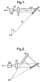
- the Littrow cavity uses a single pass through the grating, which is rotated to tune the wavelength.
- the cavity consists of a optical amplifier (OA) with one high-reflection coated end facet (10) and one anti-reflection coated facet (20), an anti-reflection coated lens (LE) and a high reflectivity blazed reflection grating (G), although other components such as etalons, cylindrical lenses, and prisms (not shown) may also be used to improve optical performance as described later.
- OA optical amplifier
- LE anti-reflection coated facet
- G high reflectivity blazed reflection grating
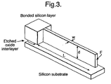
- the Littman cavity uses a double pass through the grating (G), and requires an external mirror (M), which is rotated for tuning. Spectral purity is enhanced in this geometry, because the filtering action of the grating is encountered twice per round trip.
- ⁇ 2Lc/m
- Lc the effective cavity length (i.e., the optical length of all parts of the cavity, including the laser, the lens, and the air propagation distance)
- m the mode number
- Equation 5 This construction represents the optimum mounting of the grating for synchronous tuning. Note that the result in Equation 5 is independent of both the mode number m and the grating order n, so the optimum pivot radius is unique.
- the process of aligning the laser cavity so that lasing takes place is itself relatively complicated.
- One method involves the laser (and often some other components) being mounted on flexure suspensions, allowing gradual and precise linear and angular adjustment. After lasing has been achieved, the flexures may be fixed in position by spot-welding
- a device is based on a deep etched (i.e. at least 10 micrometres deep) silicon micro-engineered breadboard which provides alignment features for the laser diode and a Graded Index (GRIN) lens, and carries an electrically-tuned blazed grating on a flexure suspension to form a Littrow cavity.
- Deep etching is described in Laermer F., Schilp A. "Method of anisotropically etching silicon” US Patent 5 501 893 March 26th (1996) and Gormley C., Yallup K., Nevin W.A., Bhardwaj J., Ashraf H., Hugget P., Blackstone S.
- the mounting is designed to be capable of initial passive adjustment, followed by dynamic wavelength tuning.
- the grating is a deep etched structure, set up normal to the wafer plane, and mounted on a novel elastic flexure suspension that mimics the action of an optimised pivot to allow wide range, mode-hop free tuning. Electrical control of grating rotation and axial mode synchronisation is by electrostatic drives, although other actuation methods may be used.
- the advantage of the invention compared with a conventional grating-tuned external cavity laser diode is that miniaturisation of the tuning mechanism will allow higher tuning speeds and improve mechanical and thermal stability, and the use of a mass fabrication technology will reduce costs.
- the use of existing stripe emitting diodes will allow output powers to be maintained at levels similar to those of fixed wavelength devices, which are typically considerably in excess of those currently achievable from VCSELs.
- An example MEMS tunable laser system is based on a laser diode hybridised on a silicon breadboard formed by deep reactive ion etching of bonded silicon-on-insulator (BSOI).
- BSOI bonded silicon-on-insulator
- This approach allows thick, strain-free suspended mechanical parts to be made in single crystal silicon.
- the Advanced Silicon Etch (ASE - a trade mark of Analog Devices (Belfast)
- ASE - a trade mark of Analog Devices (Belfast)
- process can etch silicon to depths > 350 ⁇ m at rates of ⁇ 3 ⁇ m per min, so that deep structures are economic.
- sidewall angles of 90° ⁇ 0.25°. anisotropy of > 0.99 and feature aspects of 40:1 are possible on this basis allowing the production of high quality parts.
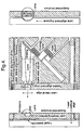
- a beam of length L and width w has been etched into the bonded layer (itself of thickness d) of a BSOI wafer by deep reactive ion etching.
- the oxide underlayer has been removed from beneath the relatively narrow beam by etching the sacrificial oxide interlayer with (for example) a wet acid etch such as buffered hydrofluoric acid.
- a wet acid etch such as buffered hydrofluoric acid.
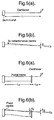
- Figure 4 shows the layout of a MEMS Littrow cavity according to a preferred embodiment. This might have dimensions ⁇ 5 mm x 6 mm: an approximate 10-fold reduction in linear dimension over conventional systems.
- the substrate has been anisotropically etched to form a buried alignment V-groove for a ⁇ 1 mm diameter quarter pitch GRIN lens prior to formation of a ⁇ 2 ⁇ m thick thermal oxide layer and attachment of a ⁇ 400 ⁇ m thick bonded silicon layer.
- the mechanical parts and grating are formed in the bonded layer.
- Two deep dry etched levels define the device: the first passes right through the bonded layer and outlines all precision features (grating, flexures, electrostatic drives), while the second passes only half-way through and forms a terrace to mount the laser approximately on the optical axis. All features are etched together, using two masks (resist and oxide), one of which is stripped (i.e. removed) half way through etching. The sacrificial oxide is then removed.
- the resultant structure is metallised to increase grating reflectivity and allow electrical connections, and solder bumps are then deposited for the laser die.
- the laser and lens mounts must be capable of one-time set-up adjustment to compensate for die bonding errors and lens outside diameter (OD) and core concentricity errors.
- the laser is therefore mounted on a two-axis flexure, while the lens alignment groove provides the third degree of freedom. Assembly of the system involves mounting the silicon breadboard on a feedback-controlled thermoelectric cooler to ensure temperature stability of the cavity, soldering the laser die in place against coarse passive alignment stops, and wire bonding.
- the cavity is aligned using external micromanipulators to slide the GRIN lens along the V-groove to achieve collimation (the least critical operation), and electrostatic actuation to flex the laser support cantilevers and correct positional errors (the most critical). Lateral adjustment is performed by electrostatic comb drives, and vertical adjustment by a parallel plate drive.
- the laser output is monitored using a scanning Fabry-Perot optical spectrum analyser until lasing is achieved. The lens and the laser supports are then fixed in position.
- first-order grating reflecting at ⁇ ⁇ 1.5 ⁇ m with ⁇ ⁇ 45° requires 0.75 ⁇ m features.
- the 1.5 ⁇ m features of a second-order grating are within the scope of direct E-beam lithography, and the resulting pattern may be transferred to the bonded silicon material using existing deep reactive ion etching techniques.
- the flexure mount used for the grating has the following attributes for mode-hop free tuning: 1) a primary end displacement that mimics rotation about an optimised pivot, and 2) a secondary linear motion that allows adjustment of the cavity length without altering the grating orientation.
- 1 dw 3 /12.
- the present invention advantageously provides a compound flexure that allows linear and angular displacements to be adjusted separately, so that both conditions 1) and 2), above, can be met.
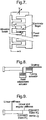
- Figure 6 shows a compound flexure consisting of a cantilever of length L2 attached to a portal frame of length L1.
- I1 12 (i.e., for beams of equal width and depth everywhere)
- the point load F needed for tuning may conveniently be applied to the cantilever using a comb-drive electrostatic microactuator, as shown in Figure 7 [103].
- Tuning of the MEMS tunable laser may therefore be performed by mounting the moving half of a comb drive electrostatic actuator on the suspension flexure as shown in Figure 8, so that the force given in Equation 16 may act to deflect the suspension.
- the deflection will be linearly related to the applied force. Because of the squared term in Equation 16, the deflection will not vary linearly with the applied voltage, however, alternative electrode geometries exist that have a linear force-voltage relationship.
- Tuning times are therefore likely to be in excess of 2 ms. This implies that tuning rates will be considerably in excess of conventional external cavity lasers.
- Figure 9 shows that the mount actually has three degrees of freedom, since it effectively contains one mass m1 mounted on a linear spring (the axial tuning actuator), coupled to another mass m2 (the grating and its actuator), which also has inertia J2 and is mounted on a spring with linear and angular stiffness. Consequently, three characteristic modes are to be expected. However, appropriate dynamic behaviour can be obtained up to the frequency of the lowest order mode.
- the selective nature of the tunable resonator of the present invention also has application in tunable optical filters advantageously offering mode hop free tuning.
Landscapes
- Physics & Mathematics (AREA)
- Condensed Matter Physics & Semiconductors (AREA)
- General Physics & Mathematics (AREA)
- Electromagnetism (AREA)
- Optics & Photonics (AREA)
- Semiconductor Lasers (AREA)
- Lasers (AREA)
- Glass Compositions (AREA)
- Mechanical Light Control Or Optical Switches (AREA)
Claims (13)
- Ein abstimmbarer optischer Resonator aufweisend einen Hohlraum, der auf einer Achse an einem Ende durch einen Reflektor und auf der gegenüberliegenden Seite durch ein Reflexionsgitter begrenzt ist; bei dem das Reflexionsgitter von einer flexiblen Halterung gehaltert ist, der optische Resonator außerdem aufweisend eine Vorrichtung zur Einstellung des Resonators entlang der Achse, in dem sie das Gitter zu einer simulierten Rotation um einen ausgewählten Punkt durch Biegung der flexiblen Halterung bringt; bei dem die flexible Halterung sich in einem Halbleitermaterial befindet.
- Der abstimmbare optische Resonator gemäß Anspruch 1, aufweisend eine Vorrichtung zur Biegung der flexiblen Halterung, um Rotation und Translation des Gitters in einer einzigen Bewegung durchzuführen.
- Der abstimmbare optische Resonator gemäß irgendeinem der obigen Ansprüche, bei dem die flexible Halterung durch Tiefätzen des Halbleitermaterials hergestellt wird.
- Der abstimmbare optische Resonator gemäß irgendeinem der obigen Ansprüche, bei dem das Reflexionsgitter ein Blazegitter aufweist.
- Der abstimmbare optische Resonator gemäß irgendeinem der obigen Ansprüche, bei dem die flexible Halterung einen Rahmen in Kombination mit einem Ausleger aufweist.
- Der abstimmbare optische Resonator gemäß Anspruch 5, bei dem der Rahmen ein fixiertes und ein freies Ende aufweist, wobei der Ausleger von dem freien Ende gestützt ist.
- Der abstimmbare optische Resonator gemäß irgendeinem der obigen Ansprüche, bei dem die Bewegung des Reflexionsgitters eine modensprungfreie Einstellung gewährleistet.
- Der abstimmbare optische Resonator gemäß irgendeinem der obigen Ansprüche aufweisend eine erste Einstellvorrichtung zur radialen Justierung der Position des Gitters und eine zweite Einstellvorrichtung für eine unabhängige axiale Einstellung der Gitterposition.
- Eine abstimmbare optische Laserlichtquelle aufweisend den abstimmbaren optischen Resonator gemäß irgendeinem der obigen Ansprüche.
- Die abstimmbare optische Laserlichtquelle gemäß Anspruch 9, bei der der Reflektor in einem optischen Verstärker enthalten ist.
- Die abstimmbare optische Laserlichtquelle gemäß einem der Ansprüche 9 oder 10 aufweisend eine streifenemittierende Diode.
- Ein abstimmbarer optischer Filter aufweisend den abstimmbaren optischen Resonator gemäß irgendeinem der Ansprüche 1 bis 8.
- Ein optisches Kommunikationssystem aufweisend den abstimmbaren optischen Resonator gemäß irgendeinem der obigen Ansprüche.
Applications Claiming Priority (3)
| Application Number | Priority Date | Filing Date | Title |
|---|---|---|---|
| GBGB0101985.0A GB0101985D0 (en) | 2001-01-25 | 2001-01-25 | Optical component |
| GB0101985 | 2001-01-25 | ||
| PCT/GB2002/000267 WO2002080319A2 (en) | 2001-01-25 | 2002-01-23 | Optical component |
Publications (2)
| Publication Number | Publication Date |
|---|---|
| EP1374355A2 EP1374355A2 (de) | 2004-01-02 |
| EP1374355B1 true EP1374355B1 (de) | 2005-10-12 |
Family
ID=9907524
Family Applications (1)
| Application Number | Title | Priority Date | Filing Date |
|---|---|---|---|
| EP02715549A Expired - Lifetime EP1374355B1 (de) | 2001-01-25 | 2002-01-23 | Optische komponente |
Country Status (8)
| Country | Link |
|---|---|
| US (1) | US7116481B2 (de) |
| EP (1) | EP1374355B1 (de) |
| CN (1) | CN1237674C (de) |
| AT (1) | ATE306729T1 (de) |
| CA (1) | CA2437110A1 (de) |
| DE (1) | DE60206610T2 (de) |
| GB (1) | GB0101985D0 (de) |
| WO (1) | WO2002080319A2 (de) |
Cited By (1)
| Publication number | Priority date | Publication date | Assignee | Title |
|---|---|---|---|---|
| EP3925038A1 (de) * | 2019-02-12 | 2021-12-22 | Laboratorio Europeo di Spettroscopie Non Lineari (Lens) | Laservorrichtung mit externem resonator, entsprechendes system und verfahren |
Families Citing this family (13)
| Publication number | Priority date | Publication date | Assignee | Title |
|---|---|---|---|---|
| GB0316448D0 (en) * | 2003-07-14 | 2003-08-20 | Univ Cambridge Tech | An extended cavity diode laser |
| JP4073886B2 (ja) * | 2004-03-30 | 2008-04-09 | アンリツ株式会社 | 可変波長光源 |
| WO2005100961A2 (en) * | 2004-04-19 | 2005-10-27 | Phoseon Technology, Inc. | Imaging semiconductor strucutures using solid state illumination |
| KR100550141B1 (ko) * | 2004-08-09 | 2006-02-08 | 한국전자통신연구원 | 가변 광 편향기를 이용한 파장 가변형 외부 공진 레이저다이오드 |
| US20070280326A1 (en) * | 2005-12-16 | 2007-12-06 | Sioptical, Inc. | External cavity laser in thin SOI with monolithic electronics |
| US7903704B2 (en) * | 2006-06-23 | 2011-03-08 | Pranalytica, Inc. | Tunable quantum cascade lasers and photoacoustic detection of trace gases, TNT, TATP and precursors acetone and hydrogen peroxide |
| WO2009054808A1 (en) * | 2007-10-26 | 2009-04-30 | Agency For Science, Technology And Research | Packaged tunable semiconductor laser structure and its fabrication |
| CN101609959B (zh) * | 2008-06-18 | 2013-01-16 | 中国计量科学研究院 | 利特罗结构光栅外腔半导体激光器和准同步调谐方法 |
| JP2012531754A (ja) * | 2009-06-30 | 2012-12-10 | 山▲東▼▲遠▼普光学股▲フン▼有限公司 | 連続モードホップフリー同調可能格子外部空洞レーザ |
| DE102014201701B4 (de) | 2014-01-30 | 2018-04-05 | Fraunhofer-Gesellschaft zur Förderung der angewandten Forschung e.V. | Mikroelektromechanisches System zum Durchstimmen von Lasern |
| EP3592227B1 (de) * | 2017-03-10 | 2022-03-02 | University of Washington | Verfahren und systeme zur messung und bewertung der stabilität von medizinischen implantaten |
| DE102018207783B4 (de) | 2018-05-17 | 2022-11-10 | Fraunhofer-Gesellschaft zur Förderung der angewandten Forschung e.V. | MEMS-Array aus MEMS mit jeweils einem beweglichen Strukturelement |
| CN109449750B (zh) * | 2018-12-14 | 2021-03-02 | 周淼淼 | 一种激光光路稳定装置 |
Family Cites Families (22)
| Publication number | Priority date | Publication date | Assignee | Title |
|---|---|---|---|---|
| US4229710A (en) | 1977-10-21 | 1980-10-21 | Itamar Shoshan | Wavelength selector for tunable laser |
| US4589115A (en) | 1983-09-09 | 1986-05-13 | Xerox Corporation | Wavelength tuning of quantum well heterostructure lasers using an external grating |
| US4942583A (en) | 1988-06-17 | 1990-07-17 | Hewlett-Packard Company | Misalignment-tolerant, grating-tuned external-cavity laser |
| SE463181B (sv) * | 1989-09-07 | 1990-10-15 | Radians Innova Ab | Saett att saekestaella modhoppsfri avstaemning av resonansfrekvens och q-vaerde hos en optisk resonator samt anordning foer utoevande av saettet |
| FR2664439A1 (fr) * | 1990-07-06 | 1992-01-10 | Alsthom Cge Alcatel | Laser semi-conducteur a reflecteur externe. |
| US5263037A (en) * | 1990-08-01 | 1993-11-16 | Hewlett-Packard Company | Optical oscillator sweeper |
| SE467474B (sv) | 1990-09-17 | 1992-07-20 | Radians Innova Ab | Positioneringsanordning |
| SE468337B (sv) | 1991-05-08 | 1992-12-14 | Radians Innova Ab | Saett att anordna och justera in en laser samt laseranordning vilken genomfoer saettet |
| US5177750A (en) | 1991-07-30 | 1993-01-05 | Hewlett-Packard Company | Misalignment-tolerant, grating-tuned external-cavity laser with enhanced longitudinal mode selectivity |
| FR2690012B1 (fr) | 1992-04-13 | 1994-07-08 | France Telecom | Procede de reglage d'une source lumineuse continument syntonisable. |
| US5319668A (en) | 1992-09-30 | 1994-06-07 | New Focus, Inc. | Tuning system for external cavity diode laser |
| DE4241045C1 (de) | 1992-12-05 | 1994-05-26 | Bosch Gmbh Robert | Verfahren zum anisotropen Ätzen von Silicium |
| JPH0766482A (ja) | 1993-08-26 | 1995-03-10 | Anritsu Corp | 可変波長光源 |
| US5579327A (en) | 1994-06-06 | 1996-11-26 | Anritsu Corporation | External-cavity tunable wavelength light source using semiconductor laser having phase adjustment area |
| FR2724496B1 (fr) | 1994-09-13 | 1996-12-20 | Photonetics | Source laser monomode accordable en longueur d'onde a cavite externe autoalignee |
| US5524012A (en) | 1994-10-27 | 1996-06-04 | New Focus, Inc. | Tunable, multiple frequency laser diode |
| JPH08172233A (ja) | 1994-12-15 | 1996-07-02 | Anritsu Corp | 可変波長光源装置 |
| US5739945A (en) | 1995-09-29 | 1998-04-14 | Tayebati; Parviz | Electrically tunable optical filter utilizing a deformable multi-layer mirror |
| US5771253A (en) | 1995-10-13 | 1998-06-23 | The Board Of Trustees Of The Leland Stanford Junior University | High performance micromechanical tunable verticle cavity surface emitting laser |
| US5629951A (en) | 1995-10-13 | 1997-05-13 | Chang-Hasnain; Constance J. | Electrostatically-controlled cantilever apparatus for continuous tuning of the resonance wavelength of a fabry-perot cavity |
| JPH10341057A (ja) | 1997-06-06 | 1998-12-22 | Ando Electric Co Ltd | 外部共振器型波長可変半導体レーザー光源およびその波長可変方法 |
| US6847661B2 (en) * | 1999-09-20 | 2005-01-25 | Iolon, Inc. | Tunable laser with microactuator |
-
2001
- 2001-01-25 GB GBGB0101985.0A patent/GB0101985D0/en not_active Ceased
-
2002
- 2002-01-23 CA CA002437110A patent/CA2437110A1/en not_active Abandoned
- 2002-01-23 WO PCT/GB2002/000267 patent/WO2002080319A2/en not_active Ceased
- 2002-01-23 CN CNB028070445A patent/CN1237674C/zh not_active Expired - Fee Related
- 2002-01-23 AT AT02715549T patent/ATE306729T1/de not_active IP Right Cessation
- 2002-01-23 US US10/470,392 patent/US7116481B2/en not_active Expired - Fee Related
- 2002-01-23 DE DE60206610T patent/DE60206610T2/de not_active Expired - Lifetime
- 2002-01-23 EP EP02715549A patent/EP1374355B1/de not_active Expired - Lifetime
Cited By (1)
| Publication number | Priority date | Publication date | Assignee | Title |
|---|---|---|---|---|
| EP3925038A1 (de) * | 2019-02-12 | 2021-12-22 | Laboratorio Europeo di Spettroscopie Non Lineari (Lens) | Laservorrichtung mit externem resonator, entsprechendes system und verfahren |
Also Published As
| Publication number | Publication date |
|---|---|
| CN1502153A (zh) | 2004-06-02 |
| WO2002080319A3 (en) | 2003-10-16 |
| ATE306729T1 (de) | 2005-10-15 |
| CN1237674C (zh) | 2006-01-18 |
| DE60206610T2 (de) | 2006-05-11 |
| GB0101985D0 (en) | 2001-03-14 |
| DE60206610D1 (de) | 2005-11-17 |
| US20040151214A1 (en) | 2004-08-05 |
| WO2002080319A2 (en) | 2002-10-10 |
| EP1374355A2 (de) | 2004-01-02 |
| CA2437110A1 (en) | 2002-10-10 |
| US7116481B2 (en) | 2006-10-03 |
Similar Documents
| Publication | Publication Date | Title |
|---|---|---|
| EP1374355B1 (de) | Optische komponente | |
| US6847661B2 (en) | Tunable laser with microactuator | |
| US6704332B2 (en) | Tunable external cavity laser | |
| EP1480302B1 (de) | Halbleiterlaser mit externem Resonator enthaltend ein Etalon und Verfahren zur Herstellung desselben | |
| US6856632B1 (en) | Widely tunable laser | |
| US20030053078A1 (en) | Microelectromechanical tunable fabry-perot wavelength monitor with thermal actuators | |
| WO1995013638A1 (en) | Hybrid external coupled cavity semiconductor laser device | |
| US20150153563A1 (en) | Wavelength tunable mems-fabry perot filter | |
| Syms et al. | MOEMS tuning element for a Littrow external cavity laser | |
| Berger et al. | Widely tunable external cavity diode laser using a MEMS electrostatic rotary actuator | |
| Liu et al. | A novel integrated micromachined tunable laser using polysilicon 3-D mirror | |
| WO2002052329A2 (en) | Triple electrode moems tunable filter and fabrication process therefor | |
| Anthon et al. | External cavity diode lasers tuned with silicon MEMS | |
| EP3837573B1 (de) | Mems/pnems-integrierte, auf unterbrochenen racetrack abstimmbare laserdiode | |
| Berger et al. | Tunable MEMS devices for optical networks | |
| Huang et al. | Precision MEMS flexure mount for a Littman tunable external cavity laser | |
| US7457033B2 (en) | MEMS tunable vertical-cavity semiconductor optical amplifier | |
| Liu et al. | Single-/multi-mode tunable lasers using MEMS mirror and grating | |
| Zhao et al. | 800 nm band MEMS-tunable VCSEL for microfabricated atomic clock | |
| Jerman et al. | A mechanically-balanced, DRIE rotary actuator for a high-power tunable laser | |
| JP2005243756A (ja) | 外部共振器型波長可変半導体レーザ装置 | |
| Liu et al. | MEMS widely tunable lasers for WDM system applications | |
| Liu et al. | Micromachined MEMS Tunable Laser for WDM System Applications | |
| EP1238448A2 (de) | Abstimmbarer laser mit einem mikroaktuator | |
| Mateus et al. | Tunable micromechanical optical filter using a torsional structure |
Legal Events
| Date | Code | Title | Description |
|---|---|---|---|
| PUAI | Public reference made under article 153(3) epc to a published international application that has entered the european phase |
Free format text: ORIGINAL CODE: 0009012 |
|
| 17P | Request for examination filed |
Effective date: 20030822 |
|
| AK | Designated contracting states |
Kind code of ref document: A2 Designated state(s): AT BE CH CY DE DK ES FI FR GB GR IE IT LI LU MC NL PT SE TR |
|
| AX | Request for extension of the european patent |
Extension state: AL LT LV MK RO SI |
|
| GRAP | Despatch of communication of intention to grant a patent |
Free format text: ORIGINAL CODE: EPIDOSNIGR1 |
|
| GRAS | Grant fee paid |
Free format text: ORIGINAL CODE: EPIDOSNIGR3 |
|
| GRAA | (expected) grant |
Free format text: ORIGINAL CODE: 0009210 |
|
| AK | Designated contracting states |
Kind code of ref document: B1 Designated state(s): AT BE CH CY DE DK ES FI FR GB GR IE IT LI LU MC NL PT SE TR |
|
| PG25 | Lapsed in a contracting state [announced via postgrant information from national office to epo] |
Ref country code: CH Free format text: LAPSE BECAUSE OF FAILURE TO SUBMIT A TRANSLATION OF THE DESCRIPTION OR TO PAY THE FEE WITHIN THE PRESCRIBED TIME-LIMIT Effective date: 20051012 Ref country code: FI Free format text: LAPSE BECAUSE OF FAILURE TO SUBMIT A TRANSLATION OF THE DESCRIPTION OR TO PAY THE FEE WITHIN THE PRESCRIBED TIME-LIMIT Effective date: 20051012 Ref country code: AT Free format text: LAPSE BECAUSE OF FAILURE TO SUBMIT A TRANSLATION OF THE DESCRIPTION OR TO PAY THE FEE WITHIN THE PRESCRIBED TIME-LIMIT Effective date: 20051012 Ref country code: BE Free format text: LAPSE BECAUSE OF FAILURE TO SUBMIT A TRANSLATION OF THE DESCRIPTION OR TO PAY THE FEE WITHIN THE PRESCRIBED TIME-LIMIT Effective date: 20051012 Ref country code: LI Free format text: LAPSE BECAUSE OF FAILURE TO SUBMIT A TRANSLATION OF THE DESCRIPTION OR TO PAY THE FEE WITHIN THE PRESCRIBED TIME-LIMIT Effective date: 20051012 |
|
| REG | Reference to a national code |
Ref country code: GB Ref legal event code: FG4D |
|
| REG | Reference to a national code |
Ref country code: CH Ref legal event code: EP |
|
| REG | Reference to a national code |
Ref country code: SE Ref legal event code: TRGR |
|
| REG | Reference to a national code |
Ref country code: IE Ref legal event code: FG4D |
|
| REF | Corresponds to: |
Ref document number: 60206610 Country of ref document: DE Date of ref document: 20051117 Kind code of ref document: P |
|
| PG25 | Lapsed in a contracting state [announced via postgrant information from national office to epo] |
Ref country code: GR Free format text: LAPSE BECAUSE OF FAILURE TO SUBMIT A TRANSLATION OF THE DESCRIPTION OR TO PAY THE FEE WITHIN THE PRESCRIBED TIME-LIMIT Effective date: 20060112 Ref country code: DK Free format text: LAPSE BECAUSE OF FAILURE TO SUBMIT A TRANSLATION OF THE DESCRIPTION OR TO PAY THE FEE WITHIN THE PRESCRIBED TIME-LIMIT Effective date: 20060112 |
|
| PG25 | Lapsed in a contracting state [announced via postgrant information from national office to epo] |
Ref country code: ES Free format text: LAPSE BECAUSE OF FAILURE TO SUBMIT A TRANSLATION OF THE DESCRIPTION OR TO PAY THE FEE WITHIN THE PRESCRIBED TIME-LIMIT Effective date: 20060123 Ref country code: IE Free format text: LAPSE BECAUSE OF NON-PAYMENT OF DUE FEES Effective date: 20060123 |
|
| PG25 | Lapsed in a contracting state [announced via postgrant information from national office to epo] |
Ref country code: LU Free format text: LAPSE BECAUSE OF NON-PAYMENT OF DUE FEES Effective date: 20060131 Ref country code: MC Free format text: LAPSE BECAUSE OF NON-PAYMENT OF DUE FEES Effective date: 20060131 |
|
| PG25 | Lapsed in a contracting state [announced via postgrant information from national office to epo] |
Ref country code: PT Free format text: LAPSE BECAUSE OF FAILURE TO SUBMIT A TRANSLATION OF THE DESCRIPTION OR TO PAY THE FEE WITHIN THE PRESCRIBED TIME-LIMIT Effective date: 20060313 |
|
| REG | Reference to a national code |
Ref country code: CH Ref legal event code: PL |
|
| ET | Fr: translation filed | ||
| REG | Reference to a national code |
Ref country code: GB Ref legal event code: 732E |
|
| PLBE | No opposition filed within time limit |
Free format text: ORIGINAL CODE: 0009261 |
|
| STAA | Information on the status of an ep patent application or granted ep patent |
Free format text: STATUS: NO OPPOSITION FILED WITHIN TIME LIMIT |
|
| 26N | No opposition filed |
Effective date: 20060713 |
|
| NLS | Nl: assignments of ep-patents |
Owner name: ERICSSON AB Effective date: 20060802 Owner name: M (DGP1) LTD Effective date: 20060802 |
|
| REG | Reference to a national code |
Ref country code: IE Ref legal event code: MM4A |
|
| REG | Reference to a national code |
Ref country code: FR Ref legal event code: TP |
|
| REG | Reference to a national code |
Ref country code: FR Ref legal event code: TP |
|
| PGFP | Annual fee paid to national office [announced via postgrant information from national office to epo] |
Ref country code: IT Payment date: 20080130 Year of fee payment: 7 Ref country code: SE Payment date: 20080129 Year of fee payment: 7 |
|
| PG25 | Lapsed in a contracting state [announced via postgrant information from national office to epo] |
Ref country code: TR Free format text: LAPSE BECAUSE OF FAILURE TO SUBMIT A TRANSLATION OF THE DESCRIPTION OR TO PAY THE FEE WITHIN THE PRESCRIBED TIME-LIMIT Effective date: 20051012 |
|
| PG25 | Lapsed in a contracting state [announced via postgrant information from national office to epo] |
Ref country code: CY Free format text: LAPSE BECAUSE OF FAILURE TO SUBMIT A TRANSLATION OF THE DESCRIPTION OR TO PAY THE FEE WITHIN THE PRESCRIBED TIME-LIMIT Effective date: 20051012 |
|
| EUG | Se: european patent has lapsed | ||
| PG25 | Lapsed in a contracting state [announced via postgrant information from national office to epo] |
Ref country code: IT Free format text: LAPSE BECAUSE OF NON-PAYMENT OF DUE FEES Effective date: 20090123 |
|
| PG25 | Lapsed in a contracting state [announced via postgrant information from national office to epo] |
Ref country code: SE Free format text: LAPSE BECAUSE OF NON-PAYMENT OF DUE FEES Effective date: 20090124 |
|
| REG | Reference to a national code |
Ref country code: FR Ref legal event code: PLFP Year of fee payment: 14 |
|
| PGFP | Annual fee paid to national office [announced via postgrant information from national office to epo] |
Ref country code: NL Payment date: 20150126 Year of fee payment: 14 |
|
| PGFP | Annual fee paid to national office [announced via postgrant information from national office to epo] |
Ref country code: DE Payment date: 20150128 Year of fee payment: 14 |
|
| PGFP | Annual fee paid to national office [announced via postgrant information from national office to epo] |
Ref country code: GB Payment date: 20150127 Year of fee payment: 14 Ref country code: FR Payment date: 20150119 Year of fee payment: 14 |
|
| REG | Reference to a national code |
Ref country code: DE Ref legal event code: R119 Ref document number: 60206610 Country of ref document: DE |
|
| GBPC | Gb: european patent ceased through non-payment of renewal fee |
Effective date: 20160123 |
|
| REG | Reference to a national code |
Ref country code: NL Ref legal event code: MM Effective date: 20160201 |
|
| REG | Reference to a national code |
Ref country code: FR Ref legal event code: ST Effective date: 20160930 |
|
| PG25 | Lapsed in a contracting state [announced via postgrant information from national office to epo] |
Ref country code: GB Free format text: LAPSE BECAUSE OF NON-PAYMENT OF DUE FEES Effective date: 20160123 Ref country code: DE Free format text: LAPSE BECAUSE OF NON-PAYMENT OF DUE FEES Effective date: 20160802 |
|
| PG25 | Lapsed in a contracting state [announced via postgrant information from national office to epo] |
Ref country code: FR Free format text: LAPSE BECAUSE OF NON-PAYMENT OF DUE FEES Effective date: 20160201 Ref country code: NL Free format text: LAPSE BECAUSE OF NON-PAYMENT OF DUE FEES Effective date: 20160201 |