EP1374797A1 - Lumière-DEL de durcissement - Google Patents
Lumière-DEL de durcissement Download PDFInfo
- Publication number
- EP1374797A1 EP1374797A1 EP03008607A EP03008607A EP1374797A1 EP 1374797 A1 EP1374797 A1 EP 1374797A1 EP 03008607 A EP03008607 A EP 03008607A EP 03008607 A EP03008607 A EP 03008607A EP 1374797 A1 EP1374797 A1 EP 1374797A1
- Authority
- EP
- European Patent Office
- Prior art keywords
- light
- lems
- light source
- curing
- leds
- Prior art date
- Legal status (The legal status is an assumption and is not a legal conclusion. Google has not performed a legal analysis and makes no representation as to the accuracy of the status listed.)
- Withdrawn
Links
- 239000000835 fiber Substances 0.000 claims description 28
- 230000003595 spectral effect Effects 0.000 claims description 15
- VYPSYNLAJGMNEJ-UHFFFAOYSA-N Silicium dioxide Chemical compound O=[Si]=O VYPSYNLAJGMNEJ-UHFFFAOYSA-N 0.000 claims description 5
- 239000005350 fused silica glass Substances 0.000 claims description 3
- XAGFODPZIPBFFR-UHFFFAOYSA-N aluminium Chemical compound [Al] XAGFODPZIPBFFR-UHFFFAOYSA-N 0.000 claims description 2
- 229910052782 aluminium Inorganic materials 0.000 claims description 2
- 239000004020 conductor Substances 0.000 claims description 2
- 230000001154 acute effect Effects 0.000 claims 1
- 230000000717 retained effect Effects 0.000 claims 1
- 239000013307 optical fiber Substances 0.000 abstract description 9
- 230000005540 biological transmission Effects 0.000 description 6
- 239000002131 composite material Substances 0.000 description 6
- 229910052736 halogen Inorganic materials 0.000 description 6
- 150000002367 halogens Chemical class 0.000 description 6
- 238000005253 cladding Methods 0.000 description 5
- 239000000463 material Substances 0.000 description 5
- 239000011350 dental composite resin Substances 0.000 description 3
- 238000005516 engineering process Methods 0.000 description 3
- 239000007788 liquid Substances 0.000 description 3
- 238000000034 method Methods 0.000 description 3
- NBIIXXVUZAFLBC-UHFFFAOYSA-N Phosphoric acid Chemical compound OP(O)(O)=O NBIIXXVUZAFLBC-UHFFFAOYSA-N 0.000 description 2
- 230000015556 catabolic process Effects 0.000 description 2
- 239000011248 coating agent Substances 0.000 description 2
- 238000000576 coating method Methods 0.000 description 2
- 238000001816 cooling Methods 0.000 description 2
- 230000007812 deficiency Effects 0.000 description 2
- 238000006731 degradation reaction Methods 0.000 description 2
- 238000004519 manufacturing process Methods 0.000 description 2
- 229920000642 polymer Polymers 0.000 description 2
- 239000000843 powder Substances 0.000 description 2
- 230000009467 reduction Effects 0.000 description 2
- 239000004450 Cordite Substances 0.000 description 1
- 244000043261 Hevea brasiliensis Species 0.000 description 1
- XUIMIQQOPSSXEZ-UHFFFAOYSA-N Silicon Chemical compound [Si] XUIMIQQOPSSXEZ-UHFFFAOYSA-N 0.000 description 1
- 238000005299 abrasion Methods 0.000 description 1
- 239000000443 aerosol Substances 0.000 description 1
- 238000007605 air drying Methods 0.000 description 1
- 229910000147 aluminium phosphate Inorganic materials 0.000 description 1
- 230000003667 anti-reflective effect Effects 0.000 description 1
- 230000002238 attenuated effect Effects 0.000 description 1
- 230000001580 bacterial effect Effects 0.000 description 1
- 229910010293 ceramic material Inorganic materials 0.000 description 1
- 238000010276 construction Methods 0.000 description 1
- 230000003247 decreasing effect Effects 0.000 description 1
- 210000004262 dental pulp cavity Anatomy 0.000 description 1
- 238000005553 drilling Methods 0.000 description 1
- 230000000694 effects Effects 0.000 description 1
- 238000001914 filtration Methods 0.000 description 1
- 230000004907 flux Effects 0.000 description 1
- 230000007794 irritation Effects 0.000 description 1
- 230000031700 light absorption Effects 0.000 description 1
- 238000000386 microscopy Methods 0.000 description 1
- 229920003052 natural elastomer Polymers 0.000 description 1
- 229920001194 natural rubber Polymers 0.000 description 1
- 230000002093 peripheral effect Effects 0.000 description 1
- 239000004033 plastic Substances 0.000 description 1
- 238000006116 polymerization reaction Methods 0.000 description 1
- 239000000377 silicon dioxide Substances 0.000 description 1
- 150000003512 tertiary amines Chemical class 0.000 description 1
- 239000006163 transport media Substances 0.000 description 1
- WFKWXMTUELFFGS-UHFFFAOYSA-N tungsten Chemical compound [W] WFKWXMTUELFFGS-UHFFFAOYSA-N 0.000 description 1
- 229910052721 tungsten Inorganic materials 0.000 description 1
- 239000010937 tungsten Substances 0.000 description 1
- 239000002918 waste heat Substances 0.000 description 1
- XLYOFNOQVPJJNP-UHFFFAOYSA-N water Substances O XLYOFNOQVPJJNP-UHFFFAOYSA-N 0.000 description 1
- 229910052724 xenon Inorganic materials 0.000 description 1
- FHNFHKCVQCLJFQ-UHFFFAOYSA-N xenon atom Chemical compound [Xe] FHNFHKCVQCLJFQ-UHFFFAOYSA-N 0.000 description 1
Images




Classifications
-
- F—MECHANICAL ENGINEERING; LIGHTING; HEATING; WEAPONS; BLASTING
- F21—LIGHTING
- F21K—NON-ELECTRIC LIGHT SOURCES USING LUMINESCENCE; LIGHT SOURCES USING ELECTROCHEMILUMINESCENCE; LIGHT SOURCES USING CHARGES OF COMBUSTIBLE MATERIAL; LIGHT SOURCES USING SEMICONDUCTOR DEVICES AS LIGHT-GENERATING ELEMENTS; LIGHT SOURCES NOT OTHERWISE PROVIDED FOR
- F21K9/00—Light sources using semiconductor devices as light-generating elements, e.g. using light-emitting diodes [LED] or lasers
-
- A—HUMAN NECESSITIES
- A61—MEDICAL OR VETERINARY SCIENCE; HYGIENE
- A61C—DENTISTRY; APPARATUS OR METHODS FOR ORAL OR DENTAL HYGIENE
- A61C19/00—Dental auxiliary appliances
- A61C19/003—Apparatus for curing resins by radiation
-
- A—HUMAN NECESSITIES
- A61—MEDICAL OR VETERINARY SCIENCE; HYGIENE
- A61N—ELECTROTHERAPY; MAGNETOTHERAPY; RADIATION THERAPY; ULTRASOUND THERAPY
- A61N5/00—Radiation therapy
- A61N5/06—Radiation therapy using light
- A61N2005/065—Light sources therefor
- A61N2005/0651—Diodes
- A61N2005/0652—Arrays of diodes
Definitions
- This invention relates to a light transmission system for curing instruments. More particularly, the invention relates to a light transmission system comprising an array of light emitting diodes (LEDs) optically coupled to a light guide arranged as a bundle of drawn optical fibers having a wide diameter at a light receiving end and a narrowed diameter at a light emitting end.
- LEDs light emitting diodes
- Dental composites employ well-known materials, and are used in a variety of dental procedures including restoration work and teeth filling after root canal procedures and other procedures requiring drilling.
- Several well-known dental composites have been sold, for example, under the trade names of BRILLIANT LINE, Z-100, TPH, CHARISMA and HERCULITE & BRODIGY.
- These composites are typically formed from liquid and powder components that are mixed together to form a paste.
- the paste is formed to have a consistency sufficiently workable and self-supporting to be applied to an opening or cavity in a tooth.
- the liquid component may comprise phosphoric acid and water, while the powder component may comprise ceramic materials such as cordite, silica or silicium oxide. After the composite is applied to a tooth, it must be cured to form a permanent bond with the tooth.
- Curing requires the liquid component to evaporate, causing the composite to harden.
- curing has been accomplished by air drying, which has had the disadvantage of requiring significant time. This time can greatly inconvenience the patient.
- light curing has become popular in the field of dentistry as a means for decreasing curing times. According to this trend, curing lights have been developed for dental curing applications.
- An example of such a curing light is illustrated by U.S. Patent No. 5,975,895, issued November 2, 1999 to Sullivan, which is hereby incorporated by reference.
- Conventional dental curing lights generally employ tungsten filament halogen lamps that incorporate a filament for generating light, a reflector for directing light and a blue filter to limit transmitted light to wavelengths in the region of 400 to 500 nanometers (nm).
- Light is typically directed from the filtered lamp to a light guide, which directs the light emanating from a light emitting end of the guide to a position adjacent to the material to be cured.
- Composites may be selected to take advantage of curing light properties.
- blue light provided by a curing light may be used to excite a camphoroquinine photo intitiator, which has a light absorption peak of 468 nm. This in turn stimulates the production of free radicals in a tertiary amine component, causing polymerization and hardening of the polymer composite.
- a problem with conventional halogen-based lights is that the lamp, filter and reflector degrade over time. This degradation is particularly accelerated, for example, by the significant heat generated by the halogen lamp. For example, this heat may cause filters to blister and cause reflectors to discolor, leading to reductions in light output and curing effectiveness. While heat may be dissipated by adding a cooling fan to the light, this fan may cause other undesired effects (for example, undesirably dispersing a bacterial aerosol that may have been topically applied by the dentist to the patient's mouth). Alternate lamp technologies using Xenon and laser light sources have been investigated, but these technologies tend to be costly, require filtration, consume large amounts of power and generate significant heat. Laser technologies also require stringent safety precautions.
- LEDs and LDs appear to be good candidate curing light sources, having excellent cost and life characteristics.
- LEDs and LDs can be designed to produce a significant portion of light output having a frequency in the desired range of 400 to 500 nm, thereby eliminating the need to incorporate supplementary spectral filters in the device. For example, much of the spectral radiant intensity for many blue LEDs peaks at 468 nm, producing an almost ideal bandwidth of the required blue light.
- LED light sources require no filters and generate little waste heat, and are thereby capable of transferring a greater percentage of applied power to generating blue light than, for example, halogen light sources. Generating little heat, they also present less risk of irritation or discomfort to the patient.
- a novel light source comprising an array of LEDs fixedly held in a LED holder such that emitters in each of the LEDs are approximately positioned along a spherical surface defined by a predetermined radius. The radius is selected in order to provided a desired focal length for the LED array.
- the array comprises 36 LEDs and has a focal length of 0.445 inches.
- the LED array is combined with a light guide having a light receiving end positioned near the focal length of the LED array.
- the light guide comprises a bundle of optical fibers, which have been progressively drawn so that the diameter of the bundle at a receiving end is between 14 and 25 millimeters (mm), and the diameter of the bundle at a light emitting end is between 3 and 13 mm.
- the large diameter at the receiving end allows the receiving end to capture substantially all of the light emitted by the LED array while being positioned at a minimum distance from the LED array. Minimizing the distance between the LED array and light guide reduces the amount of light energy lost by attenuation over this distance.
- the surface of the receiving end of the light guide may be concave and, preferably, follow a spherical surface. This surface shape reduces reflections of light transmitted by the LED array, thereby capturing more of the transmitted light and reducing light energy losses.
- a convex lens is interposed between the array and light guide of the second embodiment to further focus and curing light emitted by the LED array for transmission through the light receiving end of the light guide.
- Figure 1 illustrates a standard light transport medium in the form of an optical fiber 10.
- Optical fiber 10 includes a fiber core 12, a fiber cladding 14 and a fiber outer coating 16.
- Fiber core 12 typically serves as the portion of the fiber operative to carry light, and has an index of refraction N 1 .
- Fiber cladding 14 serves to help confine light within the core 12, and has an index of refraction N 2 , which is typically less than N 1 .
- Fiber Outer coating 16 provides protection against abrasion and other potential physical damage to fiber 10.
- a typical fiber 10 in the present inventive application might have an outer diameter between 0.001 and 0.003 inches in diameter, and have about 83 percent of its cross-sectional area comprising the core 12 and about 17 percent of its cross-sectional area comprising the cladding 14.
- Incident beam 22 from light source 20 moves across air gap 21 to strike receiving end 13 of the fiber 10 at an angle ⁇ 1 with respect to fiber centerline 15.
- Incident beam 22 is reflected at face 13 as reflected beam 24, and is refracted at face 13 as refracted beam 30.
- Reflected beam 24 makes an angle ⁇ 3 with respect to centerline 15, and refracted beam 30 makes an angle ⁇ 2 with centerline 15. Because face 13 is perpendicular to centerline 15, angle ⁇ 3 is equal to angle ⁇ 1 .
- NA .56, which correspond to critical angle of 34 degrees.
- the acceptance angle of the fiber 10 is twice the critical angle, or 68 degrees.
- the cone of light produced at the exit of the fiber will be limited to the smaller of the acceptance angle of the fiber 10 and an incident angle associated with light source 20.
- FIG. 2 illustrates a conventional curing light 40 as disclosed by U.S. Patent No. 5,975,895.
- Curing light 40 includes a halogen lamp 41 that is mounted in a reflector 42. Light reflected by reflector 42 is contained by a collector 43, and directed to light receiving end 47 of fiber optic bundle 44 and then to light emitting end 48 of bundle 44. The light reflected from lamp 41 passes through a corrective filter 49 before entering receiving end 47. Lamp 41, reflector 42, collector 43, filter 49 and receiving end 47 of fiber optic bundle 44 are each aligned along a centerline of barrel 45. Lamp 41 is powered by power and control unit 52, cooled by a fan 46, and actuated by a switch 50 in handle 51. Power and control unit 52 includes AC power cord 54 and controls 56. Controls 56 may be used, for example, to control power output and timing of the curing light 40.
- the curing light 40 of Figure 2 suffers from a number of the previously discussed difficulties associated with conventional curing lights.
- Halogen lamp 41 requires use of a costly, externally provisioned power supply 52 to power the light 40.
- Filter 49, lamp 41 and reflector elements 42, 43 are each subject to degradations over time.
- Lamp 41 produces a substantial amount of heat, necessitating both the addition of cooling fan 46 and the positioning of lamp 41 at a substantial distance from receiving end 47 of light guide 44 for patient safety.
- U.S. Patent No. 6,102,696 to Osterwalder et al. discloses an alternative curing light design using LEDs or LDs.
- the curing light 60 of Osterwalder includes, for example, a LED light source including a plurality of LEDs 61 arranged along a concave edge 63 of a circuit board 64, each LED being interconnected to the circuit board 64 at a connecting resistor 62.
- the light source produces a focused light beam having a focal point 65.
- the light source of curing light 60 solves some of the difficulties associated with other conventional curing lights, it exhibits certain other deficiencies.
- the light source is positioned in an application end 66 of the curing light 60 so that the light can be transmitted over a short distance through a window 67. Because no light guide is employed in curing light 60, the application end 66 housing the light source must be placed in close proximity to the materials being cured. Application end 66 may be relatively large, and therefore difficult to use in applications having limited physical access such as teeth fillings.
- a novel LED light source 80 illustrated in Figures 4A - 4C comprising a plurality of LEDs 81 and a LED holder 82 arranged for fixedly holding the plurality of LEDs 81 so that an emitter in each LED is approximately positioned on a spherical surface having a predetermined radius R.
- Figure 4A - 4C respectively illustrate top, side and perspective views of the novel LED light source 80.
- R can be calculated as 1.199.
- LEDs 81 in light source 80 will naturally exhibit a variety of spectral characteristics as a result of variation in associated manufacturing processes. While each of the LEDs 81 are selected to transmit light that is primarily in a spectral range of 430 nanometers (nm) to 490 nm in wavelength, individual ones of LEDs 81 will vary as to characteristic wavelength (wavelength produced with greatest intensity) and spectral range. Accordingly, one aspect of the present invention provides for selectively positioning LEDs 81 within holder 82 in accordance with their spectral characteristics. In one embodiment of the present invention, individual LEDs 81 are grouped according to their spectral characteristics and are randomly selected from these groups and positioned in holder 82. This scheme provides for a reasonably uniform spectral range and intensity across the full area of the incident light beam generated by light source 80.
- LEDs 81 may be grouped and selected so that LEDs having most desired spectral characteristics (for example, characteristic wavelength of 468 nm) occupy central positions on holder 82, and LEDs having least desired spectral characteristics occupy peripheral or outer positions on holder 82. Because peripherally-located LEDs may be positioned at or near the critical angle, this embodiment provides, for example, an incident light beam that maximizes transmission at the desired characteristic wavelength.
- spectral characteristics for example, characteristic wavelength of 468 nm
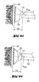
- Light guides 100 comprise a plurality of optical fibers 102 arranged in a bundle. Optical fibers 102 are heated and drawn so that a bundle diameter 104 at light emitting end 106 is substantially smaller than a bundle diameter 108 at light receiving end 110. Diameters for individual fibers in the bundle may typically range from 0.001 to 0.003 inches in diameter. As a result, light emitting end bundle diameter 104 preferably ranges between 3 and 13 millimeters, while receiving end bundle diameter 108 preferably ranges from 14 to 25 millimeters in diameter. Light receiving end bundle diameter 108 is accordingly substantially larger than bundle diameters found in conventional curing lamp guides.
- Emitting end 106 of light guide 100 may be positioned at an angle with respect to receiving end 110 (defined between longitudinal axes of emitting end 106 and receiving end 110 by tip angle ⁇ tip ).
- Light guide 100 may, for example, have a typical length 112 of between two and eight inches and a typical tip depth 114 of between 1 ⁇ 2 and 3 inches.
- Receiving end bundle diameter 108 has the advantage of enabling light guide 100 to be closely positioned with respect to light source 80 (see, for example, Figures 6A, 6B).
- rays 120 represent an outer edge limit for incident light rays generated by the light source 80.
- a minimum distance 130 between the light source 80 and receiving end 110 of light guide 100 is inversely related to the receiving end diameter 108 of the light guide 100.
- light guide 100 having an expanded receiving end diameter 108 can be positioned more closely to light source 80 than conventional light guides. As a result, less light energy is attenuated by air gap 21 as shown in Figure 1, thereby increasing light transmission through receiving end 108 of light guide 100 of Figure 6A.
- FIG. 5B A second example of light guide 100 is illustrated in Figures 5B and 6B.
- receiving end 110 of light guide 100 is formed to have a concave surface 125 that may be, for example, approximately spherical in shape.
- the concave surface 125 effectively alters the angle of refraction ⁇ 2 shown in Figure 1 so that the critical angle ⁇ 1 may be enlarged, and the amount of light reflected at angle of reflection ⁇ 3 may thereby reduced.
- comparing the light guide of Figure 5B to the light guide of Figure 5A less light energy from light source 80 is reflected by receiving end 110, thereby increasing light transmission through receiving end 110.
- FIG. 7 presents a cross-sectional view of assembly 200, comprising light guide 210, light source 230, collimating lens 240 and assembly housing 220.
- Lens 240 is fixedly positioned between light source 230 and light guide 210, and acts to further collimate light emitted by light source 230 in order to reduce the focal distance between light source 230 and light guide 210. This reduction in focal distance helps to further reduce transmissive losses between light source 230 and light guide 210.
- Collimating lens 240 is preferably an anti-reflective fused silica convex lens having a minimum of 98% transmissivity within the operative spectral range (430 nm to 490 nm), as may be commercially obtained, for example, from Thermo Electron Corporation of Waltham, Massachusetts.
- Light guide 210 is positioned through recess 225 and cavity 226 of housing 220 such that light receiving end 211 of light guide 210 is held against annular seat 227 of cavity 226.
- Recess 228 is arranged to hold an O-ring (not shown) for gripping an outer diameter of light guide 210.
- Recess 225 is arranged to engagingly receive a retaining nut (not shown) for applying sufficient lateral pressure to the O-ring in recess 228 to cause an inner diameter of the O-ring to meet and fixedly grip the outer diameter of light guide 210 in order to hold light guide 210 against annular seat 227 of cavity 226.
- a front annular surface 233 of holder 231 of light source 230 is fixedly held against seat 222 in cavity 221 of housing 220.
- a variety of conventional means may be employed to hold surface 233 against seat 222 including, for example, an interference fit between outer diameter 235 of holder 231 and inner surface 219 of cavity 221.
- Lens 240 may also be fixedly positioned by a variety of conventional means, including fixedly fitting lens 240 within cavity 224 in physical contact with conical surface 229 and covers of ones of the plurality of LEDs 234 in light source 230.
- Mounting plate 223 is fixedly mounted within cavity 221 by one of a variety of conventional means.
- Mounting plate 223 includes a variety of apertures (not shown) for receiving terminals 236 of light source 230, and may further include printed wiring paths (not shown) for interconnecting certain ones of terminals 236.
- Figures 8A - 8C illustrate a preferred example of the third embodiment of Figure 7.
- Figure 8A provides a perspective view of a light source 230a comprising LEDs 234 each individually mounted on facets 237 of holder 231. Facets 237 are configured so that emitters associated with LEDs 234 are approximately positioned on a spherical surface.
- light source 230a comprises five LEDs 234. Four of the five LEDs 234 at a periphery of holder 231 are positioned at an angle of approximately 25 degrees with respect to a fifth, centrally-located LED in order to define the approximately spherical surface.
- LEDs 234 are high output (high luminous flux) LEDs generating in excess of 160 milliwatts of output power (commercially available, for example, as LUXEON LEDs from Lumileds Lighting, LLC of San Jose, California).
- holder 231 is formed from a heat-conductive material (for example, aluminum) and incorporates fingers 238 that effectively operate as a heat sink.
- Figures 8B and 8C provide cutaway views illustrating assembly 200a comprising light source 230 fixedly positioned in housing 220a.
- Figure 8C presents a cross-sectional view of assembly 200a through section A-A of Figure 8B.
- light source 230a is fixedly held at a desired position in housing 220a by front cup 235.
- Front cup 235 provides a friction fit against a perimeter 230b of light source 230a, and may comprise a variety of materials including natural rubber and plastic.
- Light guide 210 is fixedly held in housing 200a by bushing 228a, which applies force against an outer surface of light guide 210 when compressed by front cup clamp 225a.
- Collimating lens 240a is interposed between light source 230a and light guide 210.
- Light receiving end 211 has a concave surface 211a for matingly receiving convex surface 240c of lens 240a.
- An opposing surface of lens 240a includes pockets 240b for matingly receiving dome portions of LEDs 234a. In this configuration, a viewing angle of approximately 110 degrees for LEDs 234a is collimated by lens 240 into a viewing angle of approximately 15 degrees for light rays leaving lens 240a and entering light guide 210
Landscapes
- Health & Medical Sciences (AREA)
- Engineering & Computer Science (AREA)
- Epidemiology (AREA)
- Life Sciences & Earth Sciences (AREA)
- General Engineering & Computer Science (AREA)
- Microelectronics & Electronic Packaging (AREA)
- Oral & Maxillofacial Surgery (AREA)
- Dentistry (AREA)
- Physics & Mathematics (AREA)
- Optics & Photonics (AREA)
- Animal Behavior & Ethology (AREA)
- General Health & Medical Sciences (AREA)
- Public Health (AREA)
- Veterinary Medicine (AREA)
- Optical Couplings Of Light Guides (AREA)
- Led Device Packages (AREA)
Applications Claiming Priority (2)
| Application Number | Priority Date | Filing Date | Title |
|---|---|---|---|
| US178142 | 1998-10-23 | ||
| US10/178,142 US20030235800A1 (en) | 2002-06-24 | 2002-06-24 | LED curing light |
Publications (1)
| Publication Number | Publication Date |
|---|---|
| EP1374797A1 true EP1374797A1 (fr) | 2004-01-02 |
Family
ID=29717879
Family Applications (1)
| Application Number | Title | Priority Date | Filing Date |
|---|---|---|---|
| EP03008607A Withdrawn EP1374797A1 (fr) | 2002-06-24 | 2003-04-15 | Lumière-DEL de durcissement |
Country Status (2)
| Country | Link |
|---|---|
| US (1) | US20030235800A1 (fr) |
| EP (1) | EP1374797A1 (fr) |
Cited By (10)
| Publication number | Priority date | Publication date | Assignee | Title |
|---|---|---|---|---|
| US7182597B2 (en) | 2002-08-08 | 2007-02-27 | Kerr Corporation | Curing light instrument |
| EP1953446A1 (fr) * | 2007-02-02 | 2008-08-06 | Swiss Medical Technology GmbH | Module lumineux cascadable |
| US7989839B2 (en) | 2002-08-23 | 2011-08-02 | Koninklijke Philips Electronics, N.V. | Method and apparatus for using light emitting diodes |
| US8096691B2 (en) | 1997-09-25 | 2012-01-17 | Koninklijke Philips Electronics N V | Optical irradiation device |
| US9066777B2 (en) | 2009-04-02 | 2015-06-30 | Kerr Corporation | Curing light device |
| US9072572B2 (en) | 2009-04-02 | 2015-07-07 | Kerr Corporation | Dental light device |
| US9572643B2 (en) | 1998-01-20 | 2017-02-21 | Kerr Corporation | Apparatus and method for curing materials with radiation |
| US9726435B2 (en) | 2002-07-25 | 2017-08-08 | Jonathan S. Dahm | Method and apparatus for using light emitting diodes for curing |
| EP3462811A1 (fr) * | 2017-09-29 | 2019-04-03 | Heraeus Noblelight GmbH | Dispositif de chauffage sélectif d'une cible avec un rayonnement ir |
| CN109578832A (zh) * | 2018-12-27 | 2019-04-05 | 北京华夏光谷光电科技有限公司 | 水下ld激光/led复合型照明手电筒 |
Families Citing this family (40)
| Publication number | Priority date | Publication date | Assignee | Title |
|---|---|---|---|---|
| US20020151941A1 (en) * | 2001-04-16 | 2002-10-17 | Shinichi Okawa | Medical illuminator, and medical apparatus having the medical illuminator |
| US6940659B2 (en) | 2002-01-11 | 2005-09-06 | Ultradent Products, Inc. | Cone-shaped lens having increased forward light intensity and kits incorporating such lenses |
| KR20050072152A (ko) | 2002-12-02 | 2005-07-08 | 쓰리엠 이노베이티브 프로퍼티즈 컴파니 | 복수의 광원을 사용한 조사 시스템 |
| US6890175B2 (en) | 2002-12-18 | 2005-05-10 | Ultradent Products, Inc. | Cooling system for hand-held curing light |
| US6994546B2 (en) | 2002-12-18 | 2006-02-07 | Ultradent Products, Inc. | Light curing device with detachable power supply |
| USD530013S1 (en) | 2003-02-18 | 2006-10-10 | Ultradent Products, Inc. | Dental illumination device |
| US7798692B2 (en) * | 2003-03-26 | 2010-09-21 | Optim, Inc. | Illumination device |
| US7229201B2 (en) | 2003-03-26 | 2007-06-12 | Optim Inc. | Compact, high-efficiency, high-power solid state light source using a single solid state light-emitting device |
| US20090185392A1 (en) * | 2003-03-26 | 2009-07-23 | Optim, Inc. | Detachable illumination system |
| US7579218B2 (en) * | 2003-07-23 | 2009-08-25 | Onscreen Technologies | Electronic assembly/system with reduced cost, mass, and volume and increased efficiency and power density |
| US7192276B2 (en) | 2003-08-20 | 2007-03-20 | Ultradent Products, Inc. | Dental curing light adapted to emit light at a desired angle |
| US7250611B2 (en) * | 2003-12-02 | 2007-07-31 | 3M Innovative Properties Company | LED curing apparatus and method |
| US7329887B2 (en) | 2003-12-02 | 2008-02-12 | 3M Innovative Properties Company | Solid state light device |
| US7403680B2 (en) | 2003-12-02 | 2008-07-22 | 3M Innovative Properties Company | Reflective light coupler |
| US20050116235A1 (en) * | 2003-12-02 | 2005-06-02 | Schultz John C. | Illumination assembly |
| US7144250B2 (en) | 2003-12-17 | 2006-12-05 | Ultradent Products, Inc. | Rechargeable dental curing light |
| US7456805B2 (en) | 2003-12-18 | 2008-11-25 | 3M Innovative Properties Company | Display including a solid state light device and method using same |
| US7195482B2 (en) | 2003-12-30 | 2007-03-27 | Ultradent Products, Inc. | Dental curing device having a heat sink for dissipating heat |
| US7074040B2 (en) * | 2004-03-30 | 2006-07-11 | Ultradent Products, Inc. | Ball lens for use with a dental curing light |
| US7182496B2 (en) | 2004-04-14 | 2007-02-27 | Opto Technology, Inc. | Multiple LED focused lighting device |
| US7217022B2 (en) * | 2004-08-31 | 2007-05-15 | Opto Technology, Inc. | Optic fiber LED light source |
| US7198397B2 (en) * | 2004-09-17 | 2007-04-03 | Optim, Inc. | LED endoscope illuminator and methods of mounting within an endoscope |
| US7056116B2 (en) | 2004-10-26 | 2006-06-06 | Ultradent Products, Inc. | Heat sink for dental curing light comprising a plurality of different materials |
| USRE43464E1 (en) * | 2004-12-29 | 2012-06-12 | University Of Florida Research Foundation, Incorporated | High intensity laser or diode-based lighting apparatus having integrated optics |
| US8109981B2 (en) | 2005-01-25 | 2012-02-07 | Valam Corporation | Optical therapies and devices |
| US9055863B2 (en) * | 2006-11-14 | 2015-06-16 | Optim, Inc. | Portable endoscope |
| US8152715B2 (en) | 2007-09-14 | 2012-04-10 | Optim, Incorporated | Endoscope with internal light source and power supply |
| FR2923026B1 (fr) * | 2007-10-31 | 2011-02-18 | Tokendo | Dispositif d'eclairage pour videoendoscope |
| US20090190371A1 (en) * | 2008-01-24 | 2009-07-30 | Optim, Inc. | Monolithic illumination device |
| USD619552S1 (en) * | 2009-03-05 | 2010-07-13 | Nakanishi Inc. | Light emitting diode dental handpiece |
| US20100327726A1 (en) * | 2009-06-27 | 2010-12-30 | Harris Technology, Llc | LED bulb |
| USD638944S1 (en) | 2009-09-22 | 2011-05-31 | Ultradent Products, Inc. | Dental illumination device |
| KR101819636B1 (ko) * | 2009-12-23 | 2018-01-17 | 헤라우스 노블라이트 아메리카 엘엘씨 | 컴팩트한 uv 경화 램프 어셈블리들을 위한 uv led 기반 램프 |
| DE102010013286B4 (de) * | 2010-03-29 | 2012-03-22 | Heraeus Noblelight Gmbh | LED-Lampe zur homogenen Ausleuchtung von Hohlkörpern |
| US8608328B2 (en) * | 2011-05-06 | 2013-12-17 | Teledyne Technologies Incorporated | Light source with secondary emitter conversion element |
| CH705854A2 (de) * | 2011-12-12 | 2013-06-14 | Volpi Ag | Beleuchtungsvorrichtung mit einem mischenden Lichtleitkörper. |
| WO2013151585A1 (fr) | 2012-04-05 | 2013-10-10 | American Eagle Instruments, Inc. | Dispositif et procédé de diffusion en continue acoustique induite par photons |
| US10159548B2 (en) | 2014-09-17 | 2018-12-25 | Garrison Dental Solutions, L.L.C. | Dental curing light |
| USD810293S1 (en) | 2017-01-20 | 2018-02-13 | Garrison Dental Solutions, Llc | Dental instrument |
| US11154722B1 (en) * | 2020-05-19 | 2021-10-26 | Biothread Llc | Light therapy wearable |
Citations (6)
| Publication number | Priority date | Publication date | Assignee | Title |
|---|---|---|---|---|
| JPH0910238A (ja) * | 1995-06-29 | 1997-01-14 | Osada Res Inst Ltd | 歯科用光照射器 |
| US5975895A (en) | 1997-11-12 | 1999-11-02 | Coltene/Whaledent | Strobe light curing apparatus and method |
| US6102696A (en) * | 1999-04-30 | 2000-08-15 | Osterwalder; J. Martin | Apparatus for curing resin in dentistry |
| JP2000271155A (ja) * | 1999-03-24 | 2000-10-03 | Ushio Inc | 歯科用光重合照射器 |
| WO2000067048A2 (fr) * | 1999-05-03 | 2000-11-09 | Premier Laser Systems, Inc. | Source optique et procede |
| WO2002011640A2 (fr) * | 2000-08-04 | 2002-02-14 | Kerr Corporation | Dispositif et procede pour traiter des matieres a l'aide d'un rayonnement lumineux |
Family Cites Families (23)
| Publication number | Priority date | Publication date | Assignee | Title |
|---|---|---|---|---|
| US3153283A (en) * | 1962-01-12 | 1964-10-20 | Weissman Bernard | Dowel pin assembly for dental dies |
| US3518761A (en) * | 1967-09-28 | 1970-07-07 | Harry Susman | Pin and sleeve combination to support dies in dentistry |
| DK121568B (da) * | 1970-05-27 | 1971-11-01 | G Lystager | Fremgangsmåde til fremstilling af arbejdsmodel af tand- og kæbepartier. |
| US3969820A (en) * | 1975-02-21 | 1976-07-20 | The J. M. Ney Company | Composite dowel pin for dental models |
| DE2521573C3 (de) * | 1975-05-15 | 1980-03-06 | Richard 7707 Engen Sauter | Stumpfmodellstift mit Steckhälse |
| US4363625A (en) * | 1980-08-29 | 1982-12-14 | Der Avanessian Mesrop | Dental technicians tool and tool retainer |
| US4450139A (en) * | 1982-05-03 | 1984-05-22 | Solid State Systems, Corporation | Light generating apparatus for curing dental restorative composites |
| US4820010A (en) * | 1987-04-28 | 1989-04-11 | Spectra Diode Laboratories, Inc. | Bright output optical system with tapered bundle |
| US4801264A (en) * | 1987-07-23 | 1989-01-31 | Ipco Corporation | Dental pin and bushing assembly |
| DE3810690A1 (de) * | 1988-03-29 | 1989-11-23 | Mack Heinz | Steckverbindung zur befestigung von zahn- oder kiefersegmenten auf einer modellbasis |
| US5401171A (en) * | 1992-07-20 | 1995-03-28 | Paghdiwala; Abid F. | Dental laser device and method |
| US5611686A (en) * | 1995-03-17 | 1997-03-18 | Silva; Tyrone A. | Pin stabilizer for dental model |
| US5690417A (en) * | 1996-05-13 | 1997-11-25 | Optical Gaging Products, Inc. | Surface illuminator with means for adjusting orientation and inclination of incident illumination |
| US5759032A (en) * | 1996-07-24 | 1998-06-02 | Bartel; William B. | Device for applying pressure to photocurable materials during polymerization |
| DE19636266A1 (de) * | 1996-09-06 | 1998-03-12 | Kaltenbach & Voigt | Verfahren und Vorrichtung zum Aushärten von lichtempfindlichen polymeren Zusammensetzungen |
| US6008264A (en) * | 1997-04-30 | 1999-12-28 | Laser Med, Inc. | Method for curing polymeric materials, such as those used in dentistry, and for tailoring the post-cure properties of polymeric materials through the use of light source power modulation |
| US6200134B1 (en) * | 1998-01-20 | 2001-03-13 | Kerr Corporation | Apparatus and method for curing materials with radiation |
| US6162055A (en) * | 1998-02-13 | 2000-12-19 | Britesmile, Inc. | Light activated tooth whitening composition and method of using same |
| US6193510B1 (en) * | 1999-07-28 | 2001-02-27 | Efraim Tsimerman | Medical device with time-out feature |
| US6324326B1 (en) * | 1999-08-20 | 2001-11-27 | Corning Incorporated | Tapered fiber laser |
| US6331111B1 (en) * | 1999-09-24 | 2001-12-18 | Cao Group, Inc. | Curing light system useful for curing light activated composite materials |
| DE10045543A1 (de) * | 2000-09-13 | 2002-03-28 | Degussa | Steckverbindung für Kieferstumpfmodelle |
| US6511317B2 (en) * | 2001-04-26 | 2003-01-28 | New Photonic, Llc | Device for curing photosensitive dental compositions with off-axis lens and method of curing |
-
2002
- 2002-06-24 US US10/178,142 patent/US20030235800A1/en not_active Abandoned
-
2003
- 2003-04-15 EP EP03008607A patent/EP1374797A1/fr not_active Withdrawn
Patent Citations (6)
| Publication number | Priority date | Publication date | Assignee | Title |
|---|---|---|---|---|
| JPH0910238A (ja) * | 1995-06-29 | 1997-01-14 | Osada Res Inst Ltd | 歯科用光照射器 |
| US5975895A (en) | 1997-11-12 | 1999-11-02 | Coltene/Whaledent | Strobe light curing apparatus and method |
| JP2000271155A (ja) * | 1999-03-24 | 2000-10-03 | Ushio Inc | 歯科用光重合照射器 |
| US6102696A (en) * | 1999-04-30 | 2000-08-15 | Osterwalder; J. Martin | Apparatus for curing resin in dentistry |
| WO2000067048A2 (fr) * | 1999-05-03 | 2000-11-09 | Premier Laser Systems, Inc. | Source optique et procede |
| WO2002011640A2 (fr) * | 2000-08-04 | 2002-02-14 | Kerr Corporation | Dispositif et procede pour traiter des matieres a l'aide d'un rayonnement lumineux |
Non-Patent Citations (2)
| Title |
|---|
| PATENT ABSTRACTS OF JAPAN vol. 1997, no. 05 30 May 1997 (1997-05-30) * |
| PATENT ABSTRACTS OF JAPAN vol. 2000, no. 13 5 February 2001 (2001-02-05) * |
Cited By (17)
| Publication number | Priority date | Publication date | Assignee | Title |
|---|---|---|---|---|
| US8096691B2 (en) | 1997-09-25 | 2012-01-17 | Koninklijke Philips Electronics N V | Optical irradiation device |
| US9622839B2 (en) | 1998-01-20 | 2017-04-18 | Kerr Corporation | Apparatus and method for curing materials with radiation |
| US9572643B2 (en) | 1998-01-20 | 2017-02-21 | Kerr Corporation | Apparatus and method for curing materials with radiation |
| US9726435B2 (en) | 2002-07-25 | 2017-08-08 | Jonathan S. Dahm | Method and apparatus for using light emitting diodes for curing |
| US7182597B2 (en) | 2002-08-08 | 2007-02-27 | Kerr Corporation | Curing light instrument |
| US7989839B2 (en) | 2002-08-23 | 2011-08-02 | Koninklijke Philips Electronics, N.V. | Method and apparatus for using light emitting diodes |
| EP1953446A1 (fr) * | 2007-02-02 | 2008-08-06 | Swiss Medical Technology GmbH | Module lumineux cascadable |
| WO2008092660A1 (fr) * | 2007-02-02 | 2008-08-07 | Swiss Medical Technology Gmbh | Module d'éclairage pouvant tomber en cascade |
| US9066777B2 (en) | 2009-04-02 | 2015-06-30 | Kerr Corporation | Curing light device |
| US9693846B2 (en) | 2009-04-02 | 2017-07-04 | Kerr Corporation | Dental light device |
| US9072572B2 (en) | 2009-04-02 | 2015-07-07 | Kerr Corporation | Dental light device |
| US9730778B2 (en) | 2009-04-02 | 2017-08-15 | Kerr Corporation | Curing light device |
| US9987110B2 (en) | 2009-04-02 | 2018-06-05 | Kerr Corporation | Dental light device |
| EP3462811A1 (fr) * | 2017-09-29 | 2019-04-03 | Heraeus Noblelight GmbH | Dispositif de chauffage sélectif d'une cible avec un rayonnement ir |
| WO2019063713A1 (fr) * | 2017-09-29 | 2019-04-04 | Heraeus Noblelight Gmbh | Dispositif de chauffage sélectif d'une cible par rayonnement ir |
| US11617231B2 (en) | 2017-09-29 | 2023-03-28 | Heraeus Noblelight Gmbh | Device for selectively heating a target with IR radiation |
| CN109578832A (zh) * | 2018-12-27 | 2019-04-05 | 北京华夏光谷光电科技有限公司 | 水下ld激光/led复合型照明手电筒 |
Also Published As
| Publication number | Publication date |
|---|---|
| US20030235800A1 (en) | 2003-12-25 |
Similar Documents
| Publication | Publication Date | Title |
|---|---|---|
| EP1374797A1 (fr) | Lumière-DEL de durcissement | |
| JP4393991B2 (ja) | 照射装置 | |
| US6102696A (en) | Apparatus for curing resin in dentistry | |
| CN101621969B (zh) | 具有菲涅尔透镜的led固化机 | |
| US5290169A (en) | Optical light guide for dental light-curing lamps | |
| KR100643516B1 (ko) | 의료용 광조사장치 | |
| US8231383B2 (en) | Curing light instrument | |
| US7101072B2 (en) | Photoirradiation device and fiber rod | |
| AU768286B2 (en) | Irradiation unit | |
| US7029277B2 (en) | Curing light with engineered spectrum and power compressor guide | |
| US20030215766A1 (en) | Light emitting systems and kits that include a light emitting device and one or more removable lenses | |
| EP1578295A1 (fr) | Guide de lumiere dentaire | |
| JPH0910238A (ja) | 歯科用光照射器 | |
| WO2003060574A1 (fr) | Verre retreci a intensite de lumiere directe augmentee, dispositifs de photopolymerisation et kits equipes de ces verres | |
| US20030147258A1 (en) | Curing light with plurality of LEDs and corrresponding lenses configured to focus light | |
| EP1372008A1 (fr) | Source de lumière concentrée pour un instrument de durcissement | |
| EP3134028B1 (fr) | Dispositif d'irradiation de lumière dentaire | |
| KR101608022B1 (ko) | 광섬유의 손상을 예방하는 광학구조를 갖는 치과용 레이저 핸드피스 | |
| US20050286845A1 (en) | Fiberoptic device for dental or industrial use | |
| JP3091381B2 (ja) | 医療用照光ハンドピース | |
| JP2004275276A (ja) | ファイバーロッド及び光照射装置 | |
| JP2004275277A (ja) | 光照射装置 | |
| JP2008006043A (ja) | 歯科用光重合照射器及び集光用アダプタ | |
| AU2003235591B2 (en) | Tapered lens having increased forward light intensity and light curing devices and kits incorporating such lenses | |
| HK1032523A (en) | Device for photo-activation of photosensitive composite materials especially in dentistry |
Legal Events
| Date | Code | Title | Description |
|---|---|---|---|
| PUAI | Public reference made under article 153(3) epc to a published international application that has entered the european phase |
Free format text: ORIGINAL CODE: 0009012 |
|
| AK | Designated contracting states |
Kind code of ref document: A1 Designated state(s): AT BE BG CH CY CZ DE DK EE ES FI FR GB GR HU IE IT LI LU MC NL PT RO SE SI SK TR |
|
| AX | Request for extension of the european patent |
Extension state: AL LT LV MK |
|
| 17P | Request for examination filed |
Effective date: 20040403 |
|
| AKX | Designation fees paid |
Designated state(s): DE FR GB SE |
|
| STAA | Information on the status of an ep patent application or granted ep patent |
Free format text: STATUS: THE APPLICATION IS DEEMED TO BE WITHDRAWN |
|
| 18D | Application deemed to be withdrawn |
Effective date: 20060808 |