EP1374805A2 - Modulare Kniegelenkprothese - Google Patents
Modulare Kniegelenkprothese Download PDFInfo
- Publication number
- EP1374805A2 EP1374805A2 EP03253927A EP03253927A EP1374805A2 EP 1374805 A2 EP1374805 A2 EP 1374805A2 EP 03253927 A EP03253927 A EP 03253927A EP 03253927 A EP03253927 A EP 03253927A EP 1374805 A2 EP1374805 A2 EP 1374805A2
- Authority
- EP
- European Patent Office
- Prior art keywords
- component
- channel
- joint
- joint prosthesis
- stabilizing post
- Prior art date
- Legal status (The legal status is an assumption and is not a legal conclusion. Google has not performed a legal analysis and makes no representation as to the accuracy of the status listed.)
- Granted
Links
Images


Classifications
-
- A—HUMAN NECESSITIES
- A61—MEDICAL OR VETERINARY SCIENCE; HYGIENE
- A61F—FILTERS IMPLANTABLE INTO BLOOD VESSELS; PROSTHESES; DEVICES PROVIDING PATENCY TO, OR PREVENTING COLLAPSING OF, TUBULAR STRUCTURES OF THE BODY, e.g. STENTS; ORTHOPAEDIC, NURSING OR CONTRACEPTIVE DEVICES; FOMENTATION; TREATMENT OR PROTECTION OF EYES OR EARS; BANDAGES, DRESSINGS OR ABSORBENT PADS; FIRST-AID KITS
- A61F2/00—Filters implantable into blood vessels; Prostheses, i.e. artificial substitutes or replacements for parts of the body; Appliances for connecting them with the body; Devices providing patency to, or preventing collapsing of, tubular structures of the body, e.g. stents
- A61F2/02—Prostheses implantable into the body
- A61F2/30—Joints
- A61F2/38—Joints for elbows or knees
- A61F2/3868—Joints for elbows or knees with sliding tibial bearing
-
- A—HUMAN NECESSITIES
- A61—MEDICAL OR VETERINARY SCIENCE; HYGIENE
- A61F—FILTERS IMPLANTABLE INTO BLOOD VESSELS; PROSTHESES; DEVICES PROVIDING PATENCY TO, OR PREVENTING COLLAPSING OF, TUBULAR STRUCTURES OF THE BODY, e.g. STENTS; ORTHOPAEDIC, NURSING OR CONTRACEPTIVE DEVICES; FOMENTATION; TREATMENT OR PROTECTION OF EYES OR EARS; BANDAGES, DRESSINGS OR ABSORBENT PADS; FIRST-AID KITS
- A61F2/00—Filters implantable into blood vessels; Prostheses, i.e. artificial substitutes or replacements for parts of the body; Appliances for connecting them with the body; Devices providing patency to, or preventing collapsing of, tubular structures of the body, e.g. stents
- A61F2/02—Prostheses implantable into the body
- A61F2/30—Joints
- A61F2/38—Joints for elbows or knees
- A61F2/3886—Joints for elbows or knees for stabilising knees against anterior or lateral dislocations
Definitions
- the present invention relates to prosthetic joints, and particularly to a prosthesis for the knee joint.
- Implantable knee prostheses for diseased and/or damaged knees typically include three components, namely a femoral component, a tibial component and a meniscal component.
- the femoral component may also include a patellar element, or a separate patellar component may be provided.
- the prosthesis components are generally configured to restore or emulate as much of the natural motion of the knee joint as possible. The selection of the particular prosthesis components is usually dictated by the condition of the patient's knee. For instance, the condition of the distal end of the femur and proximal end of the tibia, as well as the patency of the surrounding ligaments and soft tissue can affect the form of the joint prosthesis.
- a total knee joint replacement includes a tibial component having a platform portion which replaces the entire superior surface of the tibial plateau and substitutes for the tibial condylar surfaces.
- the femoral component also includes laterally-spaced condylar portions joined by an inter-condylar bridge and a patellar surface.
- the tibial component typically includes a tibial tray and stem for surgical attachment to the proximal end of the tibia.
- the component also includes an intermediate articulating surface member that is connected to the tibial tray.
- the intermediate member defines a bearing surface for articulation of the femoral component thereon.
- the mating surfaces are smoothly curved in the anterior-posterior (AP) direction to generally match the lateral profile of the natural femoral and tibial condyles, and to ultimately replicate the normal joint movement.
- AP anterior-posterior
- This normal joint movement includes a translational component in the AP direction, as well as a rolling of the femoral condyles on the tibial condyles when the knee is flexed.
- the natural tibia is capable of rotation relative to the femur about the axis of the tibia.
- an ideal knee prosthesis will be able to achieve all three degrees of freedom of movement.
- the patient's knee lacks adequate posterior support due to a deficient posterior cruciate ligament.
- the modular knee is preferably posteriorly stabilized, meaning that posterior movement of the tibia relative to the femur is restricted.
- This posterior stabilization can be achieved in a typical implant by a projection or eminence on the tibial insert that engages a box-like intercondylar portion of the femoral component. Intact collateral ligaments keep the projection within the box-like portion as the knee is flexed to inhibit dislocation of the joint at hyper-extension or hyper-flexion.
- the mating bearing surfaces between the tibial and femoral components generally permit a combination of rolling and translational movement as the knee joint is flexed. These two degrees of freedom of movement change the direction of forces between the two components so the force transmitted through the joint is not focussed on one location.
- some prosthetic knees include a translating intermediate bearing component.
- One problem with modular implants of this type is that the articulating and sliding components can be exposed to the soft tissue surrounding the joint.
- a modular joint prosthesis comprises a first joint component having a bone engaging portion, an articular surface, and a recess defined within the articular surface.
- the prosthesis further includes a mating component having a bone engaging portion and defining a bearing surface for sliding contact with the articular surface of the first joint component.
- a stabilizing post is slidably mounted to the mating component amid the bearing surface with the post projecting from the mating component and into the recess when the articular surface is in contact with the bearing surface.
- the mating component includes a second joint component including the bone engaging portion and an intermediate component connected to the second joint component, the intermediate component including the bearing surface.
- the first component is the femoral component
- the second component is the tibial component
- the intermediate is the meniscal component.
- the second joint component can define a bore, while the intermediate component can includes a pin sized to be received within the bore.
- the bore and pin can be configured to permit relative rotation therebetween when the pin is received within the bore to add a rotational degree of freedom between the femoral and tibial components.
- the mating component or the intermediate component defines an elongated channel.
- the stabilizing post includes a base configured for sliding engagement within the channel and a spine projecting from the base through the channel and into the recess when the articular surface is in contact with the bearing surface.
- the channel is open at one end.
- a locking member can be provided that is configured to close the one end with the base of the stabilizing post disposed within the channel. The locking member can be configured for a press-fit within the channel.
- the channel includes an enlarged groove at opposite sides of the channel.
- the base of the stabilizing post can then be configured for sliding engagement within the grooves, while the locking component can be configured for locking engagement within the grooves.
- the channel has a length greater than the length of the base so that the base can translate within the channel.
- the recess of the first joint component can define surfaces at its opposite ends.
- the stabilizing post preferably includes a face opposing each of the opposite end surfaces.
- the recess surfaces and a corresponding opposing face of the stabilizing post are configured to provide a camming movement of the stabilizing post as the recess end surface moves in contact with the opposing face.
- the camming movement causes the stabilizing post to slide between the ends of the channel.
- two faces of the stabilizing post are differently curved to provide different camming effects at opposite ends of the channel.
- a plurality of stabilizing posts can be provided having different profiles. An appropriate stabilizing post can be selected during a total knee procedure to optimize the movement of the resulting prosthetic joint.
- a further object is achieved by features of the invention that reduce the exposure of articulating surfaces and components of the prosthetic joint to soft tissue surrounding the joint.
- FIG. 1 shows a modular joint prosthesis 10 which comprises a first joint component 12, a second joint component 14 and an intermediate joint component 16.
- the first joint component 12 can be referred to as the femoral component
- the second joint component 14 as the tibial component
- the intermediate joint component 16 as the meniscal component.
- the femoral and tibial components can be configured according to known designs for these elements. For the purposes of the present disclosure, certain details of these components will be described.
- the femoral component 12 can include an articular surface, or more particularly a pair of condylar articular surfaces 25. These surfaces are smoothly curved and configured to emulate the shape of the natural femoral condyles.
- the component 12 also includes a bone engaging portion 27 which can include fixation posts 28.
- the bone engaging portion 27 can be configured in a known manner for attachment to the distal femur.
- the femur can be prepared in a conventional manner to accept the femoral component 12.
- the femoral component 12 can further include a patellar element 30 that is integral with the articular surfaces 25. A separate patellar element can also be provided for connection to the femoral component.
- the component 12 also includes an intercondylar recess 32 which is preferably a box-like structure spanning the AP dimension of the component. A slot 33 can be included in the proximal face of the recess 32.
- a tab 34 can be provided at the posterior end of the recess 32. The tab 34 can operate as a control for roll-back of the tibia relative to the femur as the joint is articulated.
- the tibial component 14 can be in the form of a conventional tibial tray.
- the component includes a proximal surface 35 that parallels the tibial plateau cut into the proximal end of the tibia to receive the component.
- a fixation stem 37 projects downwardly from the tibial tray and is configured for solid, permanent fixation within the prepared end of the tibia.
- a connection bore 39 extends from the proximal surface 35 into the fixation stem 37. The bore is configured to receive a mating stem 45 of the intermediate joint component 16 in a known fashion.
- the tibial component 14 can define a posterior recess 41.
- the intermediate component 16 can be configured like similar components from known modular knee prostheses.
- the intermediate component 16 can include opposite spaced-apart bearing surfaces 43 that are configured for articulating contact with the articular surfaces 25 of the femoral component 12.
- the component 16 can also include a rotation pin 45 that is rotatably mounted within the connection bore 39 of the tibial component 14.
- the interface between the rotation pin and the tibial component bore can be of conventional design that permits relative rotation between the intermediate component 16 and the patient's tibia.
- the axis of rotation of the intermediate component 16 is at the centre of the component and of the tibial component 14; however, other axes of rotation are contemplated as required for the particular joint anatomy and the desired movement of the joint prosthesis.
- the component 16 of the present invention includes a channel 47 defined between the spaced-apart bearing surfaces 43.
- the position of the channel 47 corresponds to the position of the recess 32 of the femoral component 12 when the two components 12 and 16 are in articulating contact.
- the channel 47 can include a posterior opening 49 at the posterior side of the intermediate component 16.
- a stop surface 51 is provided at the closed anterior end of the channel 47.
- Opposite grooves 53 can be formed at the base of the channel 47 for reasons set forth below. As shown in the figures, the channel 47 extends substantially along the entire AP length of the intermediate joint component 16.
- the channel 47 is configured to receive a further novel component of the prosthesis 10, namely the stabilizing post 18.
- the stabilizing post 18 projects upward from the intermediate component 16 to engage the intercondylar recess 32 in the femoral component 12.
- the stabilizing post 18 includes a base 55 that is sized for sliding engagement within the grooves 53 of the channel 47.
- the base 55 and grooves 53 preferably form a close running fit so that the stabilizing post 18 can slide freely within the channel 47 without binding.
- the stabilizing post 18 includes a spine 57 that projects from the base 55.
- the spine 57 is sized for sliding movement along the exposed length of the channel 47 facing the femoral component recess 32.
- the spine 57 has a height from the base 55 that is sufficient to span the height of the recess 32 and extend at least partially into the slot 33 when the femoral component and intermediate component are in articulating contact.
- the spine 57 serves to limit the AP movement of the femoral component 12.
- a close running fit between the spine 57 and the recess 32 helps ensure that the femoral component 12 does not rotate relative to the intermediate component 16, even when the tibial component rotates relative to the intermediate component.
- the joint prosthesis also includes a locking member 20 that closes the posterior opening 49 of the channel 47.
- the locking member 20 retains the stabilizing post 18 within the channel 47.
- the locking member includes locking edges 69 on opposite sides of the member that are configured for locking engagement within the grooves 53 at the posterior end of the channel 47.
- the locking edges 69 and grooves 53 can be configured to achieve a variety of locking engagements therebetween to essentially permanently connect the two parts together and close the posterior opening of the channel.
- the locking edges and grooves can form a press-fit engagement.
- the press-fit engagement can be accomplished by complementary Morse taper angles.
- the locking edges and grooves can be configured for a snap-fit engagement, sock as a locking tab and notch configuration.
- an independent fixation such as a screw of even epoxy, can be used to lock the locking member 20 within the end of the channel.
- the locking member 20 operates to trap the stabilizing post 18 within the channel.
- the member includes a stop surface 71 facing the posterior end 65 of the post 18.
- the stabilizing post also includes an opposite anterior end 63 that contacts the closed end 51 of the channel 47. The stabilizing post can thus move along the length of the channel from an anterior position 18' to a posterior position 18", as depicted in FIG. 5.
- the spine 57 of the stabilizing post 18 includes an anterior face 59 and an opposite posterior face 61. Each face exhibits a pre-defined curvature for cammed movement of the stabilizing post during articulation of the femoral component 12 on the intermediate component 16.
- the femoral component and more particularly the intercondylar recess 32, defines a posterior-facing cam surface 77 at one end of the recess and an anterior-facing cam surface 79 at the opposite end of the recess, as shown best in FIG. 6.
- the two cam surfaces 77, 79 extend from the posterior and anterior ends of the slot 33 (FIG. 1).
- cam surfaces bear against a corresponding face 59, 61 of the spine 57 to urge the stabilizing post 18 along the channel in the AP direction.
- This feature allows the femoral component 12 to both roll and slide relative to the tibial component without exposing the articulating components and surfaces to the soft tissue surrounding the joint.
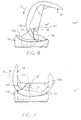
- FIG. 7 the stabilizing post 18 is in its anterior position 18' and the femur and femoral component 12 is essential at its zero degree angle relative to the tibia and tibial component 14.
- the posterior-facing cam surface 77 bears against the anterior face 59 of the spine 57.
- the cam surface 77 bears against the anterior face 59 of the spine 57 to push the stabilizing post 18 posteriorly.
- the post is pushed to its posterior position 18", as shown in FIG. 8.
- the slope and curvature of the anterior face 59 dictates the degree and speed of travel of the post along the channel 47.
- the camming surface 77 no longer contacts the spine 57 as the femoral component continues to roll and translation anteriorly relative to the tibial component.
- the femoral component is in the relative position shown in FIG. 8 in which the femur is at an angle of about 120° relative to the tibia.
- the tab 34 engages the posterior indentation 73 in the locking member 20 to prevent further relative rolling and translation (in conjunction with tension in the collateral ligaments).
- the anterior-facing cam surface 79 contacts the posterior face 61 of the spine 57.
- the sliding stabilizing post 18 of the present invention provides a significant advantage during the total knee replacement procedure.
- the specific post can be selected during the procedure and tested to verify optimum knee movement for the particular patient.
- an array of posts can be available, all with different profiles.
- the posts can be configured to permit greater or lesser movement within the channel 47.
- one or both of the faces 59, 61 can be modified to achieve a specific camming action when contacted by the femoral component cam surfaces 77, 79.
- the femoral and tibial components 12, 14 can be prepared bone surfaces.
- the intermediate or meniscal component 16 can be mounted to the tibial component 14 with the knee in flexion.
- a preselected stabilizing post 18 can be slid into the channel 47 and a temporary locking member can close the post within the channel.
- the knee can then be moved with the prosthesis in situ through certain degrees of motion to determine whether the selected post is optimum for the particular patient's anatomy. If not, the post can be removed and replaced with a different post having a different profile. Once an optimum stabilizing post has been found, the locking member 20 can be connected to the intermediate component 16 to lock the finally selected post 18 within the channel 47.
- Locking members having different lengths along the channel can be provided to allow more or less sliding movement of the stabilizing post 18 within the channel 47. In some cases, a locking member can be selected that does not permit any sliding of the post 18.
- the intermediate component 16 may be made integral with the tibial component 14. In this case, the rotational degree of freedom would be eliminated.
- the engagement of the stabilizing post 18 to the channel 47 can be modified so that the both ends of the channel are closed.
- the channel can be provided with an enlarged top opening and the base 55 of the post 18 can be configured to fit through the enlarged opening and then pivot to engage the grooves 53 at the base of the channel. Engagement of the spine 57 within the intercondylar recess 32 will prevent pivoting of the post once it is disposed within the channel.
- the channel 47 is described as including one closed end 51 and an opposite open end 49.
- both ends of the channel can be open with a corresponding locking member, such as the locking member 20, closing each end to trap the stabilizing post 18 within the channel.
- the two locking members can be selected intra-operatively to optimize and orient the translation of the stabilizing post within the channel.
Landscapes
- Health & Medical Sciences (AREA)
- Orthopedic Medicine & Surgery (AREA)
- Physical Education & Sports Medicine (AREA)
- Cardiology (AREA)
- Oral & Maxillofacial Surgery (AREA)
- Transplantation (AREA)
- Engineering & Computer Science (AREA)
- Biomedical Technology (AREA)
- Heart & Thoracic Surgery (AREA)
- Vascular Medicine (AREA)
- Life Sciences & Earth Sciences (AREA)
- Animal Behavior & Ethology (AREA)
- General Health & Medical Sciences (AREA)
- Public Health (AREA)
- Veterinary Medicine (AREA)
- Prostheses (AREA)
Applications Claiming Priority (2)
| Application Number | Priority Date | Filing Date | Title |
|---|---|---|---|
| US185492 | 2002-06-28 | ||
| US10/185,492 US20040002767A1 (en) | 2002-06-28 | 2002-06-28 | Modular knee joint prosthesis |
Publications (3)
| Publication Number | Publication Date |
|---|---|
| EP1374805A2 true EP1374805A2 (de) | 2004-01-02 |
| EP1374805A3 EP1374805A3 (de) | 2004-02-11 |
| EP1374805B1 EP1374805B1 (de) | 2012-08-22 |
Family
ID=29718002
Family Applications (1)
| Application Number | Title | Priority Date | Filing Date |
|---|---|---|---|
| EP03253927A Expired - Lifetime EP1374805B1 (de) | 2002-06-28 | 2003-06-20 | Modulare Kniegelenkprothese |
Country Status (4)
| Country | Link |
|---|---|
| US (2) | US20040002767A1 (de) |
| EP (1) | EP1374805B1 (de) |
| JP (1) | JP4307162B2 (de) |
| AU (1) | AU2003204778B2 (de) |
Cited By (11)
| Publication number | Priority date | Publication date | Assignee | Title |
|---|---|---|---|---|
| EP1591082A3 (de) * | 2004-03-17 | 2005-11-16 | Nakashima Propeller Co., Ltd. | Künstliches Kniegelenk |
| EP2149354A1 (de) * | 2008-06-30 | 2010-02-03 | DePuy Products, Inc. | Orthopädische Prothese |
| US8187335B2 (en) | 2008-06-30 | 2012-05-29 | Depuy Products, Inc. | Posterior stabilized orthopaedic knee prosthesis having controlled condylar curvature |
| US8192498B2 (en) | 2008-06-30 | 2012-06-05 | Depuy Products, Inc. | Posterior cructiate-retaining orthopaedic knee prosthesis having controlled condylar curvature |
| US8236061B2 (en) | 2008-06-30 | 2012-08-07 | Depuy Products, Inc. | Orthopaedic knee prosthesis having controlled condylar curvature |
| DE102011001885A1 (de) * | 2011-04-07 | 2012-10-11 | Aesculap Ag | Kniegelenkendoprothese |
| US9168145B2 (en) | 2008-06-30 | 2015-10-27 | Depuy (Ireland) | Posterior stabilized orthopaedic knee prosthesis having controlled condylar curvature |
| US9364332B2 (en) | 2011-09-27 | 2016-06-14 | Kyocera Medical Corporation | Artificial knee joint implant |
| US9492280B2 (en) | 2000-11-28 | 2016-11-15 | Medidea, Llc | Multiple-cam, posterior-stabilized knee prosthesis |
| US9931216B2 (en) | 2008-06-30 | 2018-04-03 | Depuy Ireland Unlimited Company | Orthopaedic femoral component having controlled condylar curvature |
| WO2020187722A1 (de) * | 2019-03-15 | 2020-09-24 | Aesculap Ag | Kniegelenkendoprothesenvorrichtung und kniegelenkendoprothese |
Families Citing this family (81)
| Publication number | Priority date | Publication date | Assignee | Title |
|---|---|---|---|---|
| US6719800B2 (en) | 2001-01-29 | 2004-04-13 | Zimmer Technology, Inc. | Constrained prosthetic knee with rotating bearing |
| US6485519B2 (en) | 2001-01-29 | 2002-11-26 | Bristol-Myers Squibb Company | Constrained prosthetic knee with rotating bearing |
| US20020120340A1 (en) | 2001-02-23 | 2002-08-29 | Metzger Robert G. | Knee joint prosthesis |
| US7497874B1 (en) | 2001-02-23 | 2009-03-03 | Biomet Manufacturing Corp. | Knee joint prosthesis |
| CA2646389A1 (en) | 2002-02-20 | 2003-08-28 | Donald M. Smucker | Knee arthroplasty prosthesis and method |
| DE50210270D1 (de) * | 2002-03-12 | 2007-07-19 | Cervitech Inc | Zwischenwirbelprothese, insbesondere für die Halswirbelsäule |
| RU2303422C2 (ru) * | 2002-03-12 | 2007-07-27 | Сервитек Инк. | Межпозвонковый протез и система межпозвонковых протезов, в частности для шейного отдела позвоночника |
| US20040054416A1 (en) * | 2002-09-12 | 2004-03-18 | Joe Wyss | Posterior stabilized knee with varus-valgus constraint |
| EP1575456B1 (de) | 2002-12-20 | 2011-02-09 | Smith & Nephew, Inc. | Hochleistungsknieprothese |
| FR2854060B1 (fr) * | 2003-04-24 | 2006-02-24 | Aesculap Sa | Prothese postero-stabilisee a plot tibial anti-basculement |
| FR2854059B1 (fr) * | 2003-04-24 | 2006-01-27 | Aesculap Sa | Plot modulaire pour prothese du genou postero-stabilisee |
| FR2854792B1 (fr) * | 2003-05-12 | 2005-09-09 | Tornier Sa | Jeu d'elements prothetiques pour un ensemble prothetique tibial |
| WO2005037147A1 (en) | 2003-10-17 | 2005-04-28 | Smith & Nephew, Inc. | High flexion articular insert |
| US7288115B2 (en) * | 2004-01-02 | 2007-10-30 | Zimmer Technology, Inc. | Multipart component for an orthopaedic implant |
| DE202004003133U1 (de) * | 2004-02-26 | 2004-07-29 | Aap Implantate Ag | Gelenkersatz-Tibiaplateau |
| US7753960B2 (en) * | 2004-02-26 | 2010-07-13 | Omni Life Science, Inc. | Modular knee prosthesis |
| US7581454B2 (en) * | 2004-05-28 | 2009-09-01 | össur hf | Method of measuring the performance of a prosthetic foot |
| US20060161259A1 (en) * | 2005-01-18 | 2006-07-20 | Cheng-Kung Cheng | Knee joint prosthesis |
| US20080288080A1 (en) * | 2005-08-24 | 2008-11-20 | Kantilal Hastimal Sancheti | Knee joint prosthesis |
| US20070116934A1 (en) * | 2005-11-22 | 2007-05-24 | Miller Scott M | Antireflective surfaces, methods of manufacture thereof and articles comprising the same |
| US7766969B2 (en) * | 2005-12-05 | 2010-08-03 | Zimmer, Inc. | Modular progressive implant for a joint articulation surface |
| US8211181B2 (en) * | 2005-12-14 | 2012-07-03 | New York University | Surface guided knee replacement |
| WO2007108933A1 (en) * | 2006-03-13 | 2007-09-27 | Mako Surgical Corp. | Prosthetic device and system and method for implanting prosthetic device |
| CN101431967A (zh) | 2006-03-21 | 2009-05-13 | 理查德·D·科米斯泰克 | 引入力矩的全关节置换假体 |
| US20070225819A1 (en) * | 2006-03-24 | 2007-09-27 | Depuy Products, Inc. | Apparatus and method for the treatment of periprosthetic fractures |
| CA2930222A1 (en) | 2006-06-30 | 2008-01-10 | Smith & Nephew, Inc. | Anatomical motion hinged prosthesis |
| US20080033567A1 (en) * | 2006-08-03 | 2008-02-07 | Stchur Robert P | Knee joint prosthesis used in total knee arthroplasty |
| US8328873B2 (en) | 2007-01-10 | 2012-12-11 | Biomet Manufacturing Corp. | Knee joint prosthesis system and method for implantation |
| US8157869B2 (en) | 2007-01-10 | 2012-04-17 | Biomet Manufacturing Corp. | Knee joint prosthesis system and method for implantation |
| US8187280B2 (en) | 2007-10-10 | 2012-05-29 | Biomet Manufacturing Corp. | Knee joint prosthesis system and method for implantation |
| US8163028B2 (en) | 2007-01-10 | 2012-04-24 | Biomet Manufacturing Corp. | Knee joint prosthesis system and method for implantation |
| US8562616B2 (en) | 2007-10-10 | 2013-10-22 | Biomet Manufacturing, Llc | Knee joint prosthesis system and method for implantation |
| US8632600B2 (en) | 2007-09-25 | 2014-01-21 | Depuy (Ireland) | Prosthesis with modular extensions |
| US9204967B2 (en) | 2007-09-28 | 2015-12-08 | Depuy (Ireland) | Fixed-bearing knee prosthesis having interchangeable components |
| US7918893B2 (en) * | 2007-09-30 | 2011-04-05 | Depuy Products, Inc. | Hinged orthopaedic prosthesis |
| CN102006839B (zh) * | 2008-02-18 | 2014-07-23 | 麦克斯外科整形公司 | 全膝关节置换假体 |
| US8377073B2 (en) | 2008-04-21 | 2013-02-19 | Ray Wasielewski | Method of designing orthopedic implants using in vivo data |
| US9119723B2 (en) | 2008-06-30 | 2015-09-01 | Depuy (Ireland) | Posterior stabilized orthopaedic prosthesis assembly |
| AU2015203508B2 (en) * | 2008-06-30 | 2017-08-17 | Depuy Products, Inc. | Orthopaedic knee prosthesis having controlled condylar curvature |
| GB0812631D0 (en) * | 2008-07-10 | 2008-08-20 | Imp Innovations Ltd | Modular knee implants |
| US8202323B2 (en) * | 2008-07-16 | 2012-06-19 | Depuy Products, Inc. | Knee prostheses with enhanced kinematics |
| US7981159B2 (en) * | 2008-07-16 | 2011-07-19 | Depuy Products, Inc. | Antero-posterior placement of axis of rotation for a rotating platform |
| US8715358B2 (en) | 2008-07-18 | 2014-05-06 | Michael A. Masini | PCL retaining ACL substituting TKA apparatus and method |
| US8078440B2 (en) * | 2008-09-19 | 2011-12-13 | Smith & Nephew, Inc. | Operatively tuning implants for increased performance |
| US8784490B2 (en) | 2008-11-18 | 2014-07-22 | Ray C. Wasielewski | Method of designing orthopedic implants using in vivo data |
| US8915965B2 (en) | 2009-05-07 | 2014-12-23 | Depuy (Ireland) | Anterior stabilized knee implant |
| ES2406366T3 (es) * | 2009-10-30 | 2013-06-06 | Depuy Products, Inc. | Prótesis con componente compuesto |
| US9271840B2 (en) | 2010-03-10 | 2016-03-01 | John Keggi | Low stress all poly tibial component |
| BR112013001673B1 (pt) | 2010-07-24 | 2021-02-09 | Zimmer, Inc | componentes de tíbia assimétrica para uma prótese de joelho |
| WO2012018563A1 (en) | 2010-07-24 | 2012-02-09 | Zimmer, Inc. | Tibial prosthesis |
| EP2603173B1 (de) | 2010-08-12 | 2016-03-23 | Smith & Nephew, Inc. | Strukturen zur verwendung bei der fixierung orthopädischer implantate |
| ES2631181T3 (es) | 2010-09-10 | 2017-08-29 | Zimmer, Inc. | Componentes de tibia que facilitan movimiento para una prótesis de rodilla |
| WO2012058560A1 (en) | 2010-10-28 | 2012-05-03 | Jerry Gerald J | Tibial tray system and method of implantation |
| US8603101B2 (en) | 2010-12-17 | 2013-12-10 | Zimmer, Inc. | Provisional tibial prosthesis system |
| US8617250B2 (en) * | 2011-06-17 | 2013-12-31 | Biomet Manufacturing, Llc | Revision knee tibial locking mechanism |
| EP2779950B1 (de) | 2011-11-18 | 2015-12-16 | Zimmer, Inc. | Schienbeinträgerkomponente für eine knieprothese mit verbesserten gelenkeigenschaften |
| CN104093380B (zh) | 2011-11-21 | 2016-08-31 | 捷迈有限公司 | 具有不对称设置的固定结构的胫骨基板 |
| WO2013086159A1 (en) * | 2011-12-07 | 2013-06-13 | Smith & Nephew, Inc. | Tibial insert with resistance-actuated post |
| EP3492044A1 (de) * | 2011-12-07 | 2019-06-05 | Smith & Nephew, Inc | Erprobung eines posterioren stabilisierten einsatzes mit einstellbarem stab |
| CN104203160B (zh) | 2012-01-30 | 2016-05-11 | 捷迈有限公司 | 用于膝关节假体的不对称胫骨件 |
| JP2015533608A (ja) * | 2012-11-07 | 2015-11-26 | ウク カン,ヒョン | 大腿膝インプラントシステム用大腿骨コンポーネント |
| KR101407608B1 (ko) | 2012-12-24 | 2014-06-13 | 충남대학교산학협력단 | 포스트-캠형 인공슬관절의 충격흡수형 조립식 베어링 시스템 |
| US9585758B2 (en) | 2013-03-12 | 2017-03-07 | Biomet Manufacturing, Llc | Knee prosthesis systems and methods |
| US10130480B2 (en) | 2013-03-13 | 2018-11-20 | Howmedica Osteonics Corp. | Modular patella trials |
| US9925052B2 (en) | 2013-08-30 | 2018-03-27 | Zimmer, Inc. | Method for optimizing implant designs |
| KR101696608B1 (ko) * | 2014-11-07 | 2017-01-17 | 주식회사 코렌텍 | 대퇴골 결합부재의 탈구를 방지할 수 있는 인공 슬관절 |
| US10278827B2 (en) | 2015-09-21 | 2019-05-07 | Zimmer, Inc. | Prosthesis system including tibial bearing component |
| US10179052B2 (en) | 2016-07-28 | 2019-01-15 | Depuy Ireland Unlimited Company | Total knee implant prosthesis assembly and method |
| ES3025978T3 (en) | 2017-03-10 | 2025-06-10 | Zimmer Inc | Tibial prosthesis with tibial bearing component securing feature |
| CN110636818B (zh) | 2017-05-12 | 2021-06-04 | 捷迈有限公司 | 具有尺码增大和尺码缩小能力的股骨假体 |
| US10925743B2 (en) * | 2017-09-26 | 2021-02-23 | Stephen J. Incavo | Knee arthroplasty with modular femoral adapters |
| RU179634U1 (ru) * | 2017-10-06 | 2018-05-21 | Федеральное Государственное Бюджетное Образовательное Учреждение Высшего Образования "Новосибирский Государственный Технический Университет" | Эндопротез коленного сустава |
| US11426282B2 (en) | 2017-11-16 | 2022-08-30 | Zimmer, Inc. | Implants for adding joint inclination to a knee arthroplasty |
| US10835380B2 (en) | 2018-04-30 | 2020-11-17 | Zimmer, Inc. | Posterior stabilized prosthesis system |
| US10736748B2 (en) | 2018-05-02 | 2020-08-11 | Depuy Ireland Unlimited Company | Orthopaedic prosthetic system for a hinged-knee prosthesis |
| US11116641B2 (en) | 2019-02-05 | 2021-09-14 | Depuy Ireland Unlimited Company | Orthopaedic prosthetic system for a rotating hinged-knee prosthesis |
| US11033396B2 (en) | 2019-02-05 | 2021-06-15 | Depuy Ireland Unlimited Company | Orthopaedic prosthetic system for a rotating hinged-knee prosthesis |
| US11141291B2 (en) * | 2019-06-30 | 2021-10-12 | Depuy Ireland Unlimited Company | Femoral trial components and associated orthopaedic surgical method of use |
| US11419731B1 (en) * | 2021-02-04 | 2022-08-23 | Jonathan P. GARINO | Modular artificial knee system |
| US12193941B2 (en) | 2021-04-23 | 2025-01-14 | Gerald J. Jerry | Tibial-tray system |
| CN113796998B (zh) | 2021-08-20 | 2023-12-19 | 北京纳通医疗科技控股有限公司 | 股骨假体和具有其的膝关节假体 |
Citations (1)
| Publication number | Priority date | Publication date | Assignee | Title |
|---|---|---|---|---|
| FR2751204A1 (fr) | 1996-07-16 | 1998-01-23 | Landanger Camus Sa | Prothese de genou, en particulier prothese de reprise |
Family Cites Families (17)
| Publication number | Priority date | Publication date | Assignee | Title |
|---|---|---|---|---|
| US5370701A (en) * | 1990-09-28 | 1994-12-06 | Arch Development Corporation | Rotating/sliding contrained prosthetic knee |
| US5282868A (en) * | 1991-06-17 | 1994-02-01 | Andre Bahler | Prosthetic arrangement for a complex joint, especially knee joint |
| US5395401A (en) * | 1991-06-17 | 1995-03-07 | Bahler; Andre | Prosthetic device for a complex joint |
| CH686401A5 (de) * | 1992-01-14 | 1996-03-29 | Wehrli Ueli Dr | Meniskusplattform zu einem kuenstlichen Kniegelenk. |
| US6102954A (en) * | 1992-05-18 | 2000-08-15 | Astra Aktiebolag | Joint prosthesis and apparatus for preparing the bone prior to fitting of the prosthesis |
| FR2692476B1 (fr) * | 1992-06-23 | 1994-10-07 | Medinov Sa | Prothèse totale du genou, du type à glissement. |
| US5370699A (en) * | 1993-01-21 | 1994-12-06 | Orthomet, Inc. | Modular knee joint prosthesis |
| GB9415180D0 (en) * | 1994-07-28 | 1994-09-21 | Walker Peter S | Stabilised mobile bearing knee |
| US6117175A (en) * | 1994-08-22 | 2000-09-12 | Bosredon; Jean | Spherical knee joint prosthesis |
| US5776201A (en) * | 1995-10-02 | 1998-07-07 | Johnson & Johnson Professional, Inc. | Modular femoral trial system |
| US5824103A (en) * | 1997-05-12 | 1998-10-20 | Howmedica Inc. | Tibial prosthesis |
| US6080195A (en) * | 1998-07-08 | 2000-06-27 | Johnson & Johnson Professional, Inc. | Rotatable and translatable joint prosthesis with posterior stabilization |
| US6629999B1 (en) * | 1999-03-08 | 2003-10-07 | Louis A. Serafin, Jr. | Modular joint |
| US6319283B1 (en) * | 1999-07-02 | 2001-11-20 | Bristol-Myers Squibb Company | Tibial knee component with a mobile bearing |
| US6210445B1 (en) * | 1999-10-26 | 2001-04-03 | Bristol-Myers Squibb Company | Tibial knee component with a mobile bearing |
| FR2805454B1 (fr) * | 2000-02-24 | 2003-01-10 | Aesculap Sa | Prothese du genou a cavite dans la trochlee |
| US6491726B2 (en) * | 2000-03-08 | 2002-12-10 | Biomedical Engineering Trust I | Posterior stabilized prosthetic knee replacement with bearing translation and dislocation prevention features |
-
2002
- 2002-06-28 US US10/185,492 patent/US20040002767A1/en not_active Abandoned
-
2003
- 2003-06-18 AU AU2003204778A patent/AU2003204778B2/en not_active Ceased
- 2003-06-20 EP EP03253927A patent/EP1374805B1/de not_active Expired - Lifetime
- 2003-06-27 JP JP2003185577A patent/JP4307162B2/ja not_active Expired - Fee Related
-
2004
- 2004-02-17 US US10/779,898 patent/US6926738B2/en not_active Expired - Lifetime
Patent Citations (1)
| Publication number | Priority date | Publication date | Assignee | Title |
|---|---|---|---|---|
| FR2751204A1 (fr) | 1996-07-16 | 1998-01-23 | Landanger Camus Sa | Prothese de genou, en particulier prothese de reprise |
Cited By (31)
| Publication number | Priority date | Publication date | Assignee | Title |
|---|---|---|---|---|
| US9492280B2 (en) | 2000-11-28 | 2016-11-15 | Medidea, Llc | Multiple-cam, posterior-stabilized knee prosthesis |
| US10188521B2 (en) | 2000-11-28 | 2019-01-29 | Medidea, Llc | Multiple-cam, posterior-stabilized knee prosthesis |
| EP1591082A3 (de) * | 2004-03-17 | 2005-11-16 | Nakashima Propeller Co., Ltd. | Künstliches Kniegelenk |
| US7678152B2 (en) | 2004-03-17 | 2010-03-16 | Toru Suguro | Artificial knee joint |
| US10543098B2 (en) | 2008-06-30 | 2020-01-28 | Depuy Ireland Unlimited Company | Orthopaedic femoral component having controlled condylar curvature |
| US9937049B2 (en) | 2008-06-30 | 2018-04-10 | Depuy Ireland Unlimited Company | Orthopaedic knee prosthesis having controlled condylar curvature |
| US8236061B2 (en) | 2008-06-30 | 2012-08-07 | Depuy Products, Inc. | Orthopaedic knee prosthesis having controlled condylar curvature |
| US12109119B2 (en) | 2008-06-30 | 2024-10-08 | Depuy Ireland Unlimited Company | Orthopaedic femoral component having controlled condylar curvature |
| US8784496B2 (en) | 2008-06-30 | 2014-07-22 | Depuy (Ireland) | Orthopaedic knee prosthesis having controlled condylar curvature |
| US8834575B2 (en) | 2008-06-30 | 2014-09-16 | Depuy (Ireland) | Posterior stabilized orthopaedic knee prosthesis having controlled condylar curvature |
| EP2878283A1 (de) * | 2008-06-30 | 2015-06-03 | DePuy (Ireland) | Orthopädische Prothese |
| US9168145B2 (en) | 2008-06-30 | 2015-10-27 | Depuy (Ireland) | Posterior stabilized orthopaedic knee prosthesis having controlled condylar curvature |
| US9326864B2 (en) | 2008-06-30 | 2016-05-03 | Depuy (Ireland) | Orthopaedic knee prosthesis having controlled condylar curvature |
| US12059356B2 (en) | 2008-06-30 | 2024-08-13 | Depuy Ireland Unlimited Company | Orthopaedic knee prosthesis having controlled condylar curvature |
| US9452053B2 (en) | 2008-06-30 | 2016-09-27 | Depuy (Ireland) | Orthopaedic knee prosthesis having controlled condylar curvature |
| US8192498B2 (en) | 2008-06-30 | 2012-06-05 | Depuy Products, Inc. | Posterior cructiate-retaining orthopaedic knee prosthesis having controlled condylar curvature |
| US9931216B2 (en) | 2008-06-30 | 2018-04-03 | Depuy Ireland Unlimited Company | Orthopaedic femoral component having controlled condylar curvature |
| US8206451B2 (en) | 2008-06-30 | 2012-06-26 | Depuy Products, Inc. | Posterior stabilized orthopaedic prosthesis |
| US10179051B2 (en) | 2008-06-30 | 2019-01-15 | Depuy Ireland Unlimited Company | Orthopaedic knee prosthesis having controlled condylar curvature |
| US8187335B2 (en) | 2008-06-30 | 2012-05-29 | Depuy Products, Inc. | Posterior stabilized orthopaedic knee prosthesis having controlled condylar curvature |
| US10265180B2 (en) | 2008-06-30 | 2019-04-23 | Depuy Ireland Unlimited Company | Orthopaedic knee prosthesis having controlled condylar curvature |
| EP2149354A1 (de) * | 2008-06-30 | 2010-02-03 | DePuy Products, Inc. | Orthopädische Prothese |
| US10729551B2 (en) | 2008-06-30 | 2020-08-04 | Depuy Ireland Unlimited Company | Orthopaedic knee prosthesis having controlled condylar curvature |
| US11730602B2 (en) | 2008-06-30 | 2023-08-22 | Depuy Ireland Unlimited Company | Orthopaedic knee prosthesis having controlled condylar curvature |
| US10849760B2 (en) | 2008-06-30 | 2020-12-01 | Depuy Ireland Unlimited Company | Orthopaedic knee prosthesis having controlled condylar curvature |
| US11337823B2 (en) | 2008-06-30 | 2022-05-24 | Depuy Ireland Unlimited Company | Orthopaedic femoral component having controlled condylar curvature |
| US11369478B2 (en) | 2008-06-30 | 2022-06-28 | Depuy Ireland Unlimited Company | Orthopaedic knee prosthesis having controlled condylar curvature |
| DE102011001885A1 (de) * | 2011-04-07 | 2012-10-11 | Aesculap Ag | Kniegelenkendoprothese |
| DE102011001885B4 (de) | 2011-04-07 | 2025-03-27 | Aesculap Ag | Kniegelenkendoprothese |
| US9364332B2 (en) | 2011-09-27 | 2016-06-14 | Kyocera Medical Corporation | Artificial knee joint implant |
| WO2020187722A1 (de) * | 2019-03-15 | 2020-09-24 | Aesculap Ag | Kniegelenkendoprothesenvorrichtung und kniegelenkendoprothese |
Also Published As
| Publication number | Publication date |
|---|---|
| US20040002767A1 (en) | 2004-01-01 |
| AU2003204778B2 (en) | 2009-04-09 |
| EP1374805A3 (de) | 2004-02-11 |
| US20040162620A1 (en) | 2004-08-19 |
| US6926738B2 (en) | 2005-08-09 |
| AU2003204778A1 (en) | 2004-01-22 |
| EP1374805B1 (de) | 2012-08-22 |
| JP4307162B2 (ja) | 2009-08-05 |
| JP2004160179A (ja) | 2004-06-10 |
Similar Documents
| Publication | Publication Date | Title |
|---|---|---|
| EP1374805B1 (de) | Modulare Kniegelenkprothese | |
| EP1400220B1 (de) | Posterior stabilisierte Knieprothese mit Varus/Valgus- Einschränkung | |
| US12383405B2 (en) | Anatomical motion hinged prosthesis | |
| US8715358B2 (en) | PCL retaining ACL substituting TKA apparatus and method | |
| US6206926B1 (en) | Prosthetic knee joint with enhanced posterior stabilization and dislocation prevention features | |
| KR100592895B1 (ko) | 무릎관절보철기구 | |
| EP1604623B1 (de) | Posterior-stabilisierte Knieprothese mit beweglichem Lager | |
| EP1333785B1 (de) | Schwimmend stützende kniegelenksprothese mit fixiertem tibialpfosten | |
| US5370699A (en) | Modular knee joint prosthesis | |
| US8292964B2 (en) | Surface guided knee replacement | |
| JPH0245456B2 (de) | ||
| US20020156535A1 (en) | Posterior stabilized knee replacement with bearing translation for knees with retained collateral ligaments | |
| EP0916321B1 (de) | Kniegelenkendprothese mit verbesserter hinterer Stabilität und Massnahmen zur Verhinderung einer Dislokation | |
| JP2001252296A (ja) | 膝義肢大腿骨部及びこれを用いた膝義肢 | |
| US9387084B2 (en) | Anterior stabilized PCL retaining total knee prosthesis | |
| US20250241760A1 (en) | Constrained prosthetic knee | |
| CA2217844C (en) | Prosthetic knee joint with enhanced posterior stabilization |
Legal Events
| Date | Code | Title | Description |
|---|---|---|---|
| PUAI | Public reference made under article 153(3) epc to a published international application that has entered the european phase |
Free format text: ORIGINAL CODE: 0009012 |
|
| PUAL | Search report despatched |
Free format text: ORIGINAL CODE: 0009013 |
|
| AK | Designated contracting states |
Kind code of ref document: A2 Designated state(s): AT BE BG CH CY CZ DE DK EE ES FI FR GB GR HU IE IT LI LU MC NL PT RO SE SI SK TR |
|
| AX | Request for extension of the european patent |
Extension state: AL LT LV MK |
|
| AK | Designated contracting states |
Kind code of ref document: A3 Designated state(s): AT BE BG CH CY CZ DE DK EE ES FI FR GB GR HU IE IT LI LU MC NL PT RO SE SI SK TR |
|
| AX | Request for extension of the european patent |
Extension state: AL LT LV MK |
|
| 17P | Request for examination filed |
Effective date: 20040705 |
|
| AKX | Designation fees paid |
Designated state(s): AT BE BG CH CY CZ DE DK EE ES FI FR GB GR HU IE IT LI LU MC NL PT RO SE SI SK TR |
|
| 17Q | First examination report despatched |
Effective date: 20070703 |
|
| GRAP | Despatch of communication of intention to grant a patent |
Free format text: ORIGINAL CODE: EPIDOSNIGR1 |
|
| GRAS | Grant fee paid |
Free format text: ORIGINAL CODE: EPIDOSNIGR3 |
|
| GRAA | (expected) grant |
Free format text: ORIGINAL CODE: 0009210 |
|
| AK | Designated contracting states |
Kind code of ref document: B1 Designated state(s): AT BE BG CH CY CZ DE DK EE ES FI FR GB GR HU IE IT LI LU MC NL PT RO SE SI SK TR |
|
| REG | Reference to a national code |
Ref country code: GB Ref legal event code: FG4D |
|
| REG | Reference to a national code |
Ref country code: CH Ref legal event code: EP Ref country code: CH Ref legal event code: NV Representative=s name: E. BLUM & CO. AG PATENT- UND MARKENANWAELTE VSP |
|
| REG | Reference to a national code |
Ref country code: IE Ref legal event code: FG4D |
|
| REG | Reference to a national code |
Ref country code: AT Ref legal event code: REF Ref document number: 571510 Country of ref document: AT Kind code of ref document: T Effective date: 20120915 |
|
| REG | Reference to a national code |
Ref country code: DE Ref legal event code: R096 Ref document number: 60341878 Country of ref document: DE Effective date: 20121018 |
|
| REG | Reference to a national code |
Ref country code: NL Ref legal event code: VDEP Effective date: 20120822 |
|
| REG | Reference to a national code |
Ref country code: AT Ref legal event code: MK05 Ref document number: 571510 Country of ref document: AT Kind code of ref document: T Effective date: 20120822 |
|
| PG25 | Lapsed in a contracting state [announced via postgrant information from national office to epo] |
Ref country code: CY Free format text: LAPSE BECAUSE OF FAILURE TO SUBMIT A TRANSLATION OF THE DESCRIPTION OR TO PAY THE FEE WITHIN THE PRESCRIBED TIME-LIMIT Effective date: 20120822 Ref country code: AT Free format text: LAPSE BECAUSE OF FAILURE TO SUBMIT A TRANSLATION OF THE DESCRIPTION OR TO PAY THE FEE WITHIN THE PRESCRIBED TIME-LIMIT Effective date: 20120822 Ref country code: FI Free format text: LAPSE BECAUSE OF FAILURE TO SUBMIT A TRANSLATION OF THE DESCRIPTION OR TO PAY THE FEE WITHIN THE PRESCRIBED TIME-LIMIT Effective date: 20120822 |
|
| PG25 | Lapsed in a contracting state [announced via postgrant information from national office to epo] |
Ref country code: BE Free format text: LAPSE BECAUSE OF FAILURE TO SUBMIT A TRANSLATION OF THE DESCRIPTION OR TO PAY THE FEE WITHIN THE PRESCRIBED TIME-LIMIT Effective date: 20120822 Ref country code: PT Free format text: LAPSE BECAUSE OF FAILURE TO SUBMIT A TRANSLATION OF THE DESCRIPTION OR TO PAY THE FEE WITHIN THE PRESCRIBED TIME-LIMIT Effective date: 20121224 Ref country code: GR Free format text: LAPSE BECAUSE OF FAILURE TO SUBMIT A TRANSLATION OF THE DESCRIPTION OR TO PAY THE FEE WITHIN THE PRESCRIBED TIME-LIMIT Effective date: 20121123 Ref country code: SI Free format text: LAPSE BECAUSE OF FAILURE TO SUBMIT A TRANSLATION OF THE DESCRIPTION OR TO PAY THE FEE WITHIN THE PRESCRIBED TIME-LIMIT Effective date: 20120822 Ref country code: SE Free format text: LAPSE BECAUSE OF FAILURE TO SUBMIT A TRANSLATION OF THE DESCRIPTION OR TO PAY THE FEE WITHIN THE PRESCRIBED TIME-LIMIT Effective date: 20120822 |
|
| PG25 | Lapsed in a contracting state [announced via postgrant information from national office to epo] |
Ref country code: NL Free format text: LAPSE BECAUSE OF FAILURE TO SUBMIT A TRANSLATION OF THE DESCRIPTION OR TO PAY THE FEE WITHIN THE PRESCRIBED TIME-LIMIT Effective date: 20120822 |
|
| PG25 | Lapsed in a contracting state [announced via postgrant information from national office to epo] |
Ref country code: DK Free format text: LAPSE BECAUSE OF FAILURE TO SUBMIT A TRANSLATION OF THE DESCRIPTION OR TO PAY THE FEE WITHIN THE PRESCRIBED TIME-LIMIT Effective date: 20120822 Ref country code: RO Free format text: LAPSE BECAUSE OF FAILURE TO SUBMIT A TRANSLATION OF THE DESCRIPTION OR TO PAY THE FEE WITHIN THE PRESCRIBED TIME-LIMIT Effective date: 20120822 Ref country code: ES Free format text: LAPSE BECAUSE OF FAILURE TO SUBMIT A TRANSLATION OF THE DESCRIPTION OR TO PAY THE FEE WITHIN THE PRESCRIBED TIME-LIMIT Effective date: 20121203 Ref country code: EE Free format text: LAPSE BECAUSE OF FAILURE TO SUBMIT A TRANSLATION OF THE DESCRIPTION OR TO PAY THE FEE WITHIN THE PRESCRIBED TIME-LIMIT Effective date: 20120822 Ref country code: CZ Free format text: LAPSE BECAUSE OF FAILURE TO SUBMIT A TRANSLATION OF THE DESCRIPTION OR TO PAY THE FEE WITHIN THE PRESCRIBED TIME-LIMIT Effective date: 20120822 |
|
| PG25 | Lapsed in a contracting state [announced via postgrant information from national office to epo] |
Ref country code: SK Free format text: LAPSE BECAUSE OF FAILURE TO SUBMIT A TRANSLATION OF THE DESCRIPTION OR TO PAY THE FEE WITHIN THE PRESCRIBED TIME-LIMIT Effective date: 20120822 |
|
| PLBE | No opposition filed within time limit |
Free format text: ORIGINAL CODE: 0009261 |
|
| STAA | Information on the status of an ep patent application or granted ep patent |
Free format text: STATUS: NO OPPOSITION FILED WITHIN TIME LIMIT |
|
| 26N | No opposition filed |
Effective date: 20130523 |
|
| PG25 | Lapsed in a contracting state [announced via postgrant information from national office to epo] |
Ref country code: BG Free format text: LAPSE BECAUSE OF FAILURE TO SUBMIT A TRANSLATION OF THE DESCRIPTION OR TO PAY THE FEE WITHIN THE PRESCRIBED TIME-LIMIT Effective date: 20121122 |
|
| REG | Reference to a national code |
Ref country code: DE Ref legal event code: R097 Ref document number: 60341878 Country of ref document: DE Effective date: 20130523 |
|
| PG25 | Lapsed in a contracting state [announced via postgrant information from national office to epo] |
Ref country code: MC Free format text: LAPSE BECAUSE OF FAILURE TO SUBMIT A TRANSLATION OF THE DESCRIPTION OR TO PAY THE FEE WITHIN THE PRESCRIBED TIME-LIMIT Effective date: 20120822 |
|
| PG25 | Lapsed in a contracting state [announced via postgrant information from national office to epo] |
Ref country code: TR Free format text: LAPSE BECAUSE OF FAILURE TO SUBMIT A TRANSLATION OF THE DESCRIPTION OR TO PAY THE FEE WITHIN THE PRESCRIBED TIME-LIMIT Effective date: 20120822 |
|
| PG25 | Lapsed in a contracting state [announced via postgrant information from national office to epo] |
Ref country code: HU Free format text: LAPSE BECAUSE OF FAILURE TO SUBMIT A TRANSLATION OF THE DESCRIPTION OR TO PAY THE FEE WITHIN THE PRESCRIBED TIME-LIMIT; INVALID AB INITIO Effective date: 20030620 Ref country code: LU Free format text: LAPSE BECAUSE OF NON-PAYMENT OF DUE FEES Effective date: 20130620 |
|
| REG | Reference to a national code |
Ref country code: FR Ref legal event code: PLFP Year of fee payment: 14 |
|
| REG | Reference to a national code |
Ref country code: FR Ref legal event code: PLFP Year of fee payment: 15 |
|
| PGFP | Annual fee paid to national office [announced via postgrant information from national office to epo] |
Ref country code: DE Payment date: 20170613 Year of fee payment: 15 Ref country code: FR Payment date: 20170511 Year of fee payment: 15 Ref country code: CH Payment date: 20170613 Year of fee payment: 15 Ref country code: IE Payment date: 20170609 Year of fee payment: 15 Ref country code: GB Payment date: 20170614 Year of fee payment: 15 |
|
| PGFP | Annual fee paid to national office [announced via postgrant information from national office to epo] |
Ref country code: IT Payment date: 20170619 Year of fee payment: 15 |
|
| REG | Reference to a national code |
Ref country code: DE Ref legal event code: R119 Ref document number: 60341878 Country of ref document: DE |
|
| REG | Reference to a national code |
Ref country code: CH Ref legal event code: PL |
|
| GBPC | Gb: european patent ceased through non-payment of renewal fee |
Effective date: 20180620 |
|
| REG | Reference to a national code |
Ref country code: IE Ref legal event code: MM4A |
|
| PG25 | Lapsed in a contracting state [announced via postgrant information from national office to epo] |
Ref country code: IE Free format text: LAPSE BECAUSE OF NON-PAYMENT OF DUE FEES Effective date: 20180620 Ref country code: GB Free format text: LAPSE BECAUSE OF NON-PAYMENT OF DUE FEES Effective date: 20180620 Ref country code: IT Free format text: LAPSE BECAUSE OF NON-PAYMENT OF DUE FEES Effective date: 20180620 Ref country code: DE Free format text: LAPSE BECAUSE OF NON-PAYMENT OF DUE FEES Effective date: 20190101 Ref country code: FR Free format text: LAPSE BECAUSE OF NON-PAYMENT OF DUE FEES Effective date: 20180630 Ref country code: CH Free format text: LAPSE BECAUSE OF NON-PAYMENT OF DUE FEES Effective date: 20180630 Ref country code: LI Free format text: LAPSE BECAUSE OF NON-PAYMENT OF DUE FEES Effective date: 20180630 |