EP1374823B1 - Elément de fixation pour attacher des accessoires au surface de couchage d'une table d'opération - Google Patents
Elément de fixation pour attacher des accessoires au surface de couchage d'une table d'opération Download PDFInfo
- Publication number
- EP1374823B1 EP1374823B1 EP03008286A EP03008286A EP1374823B1 EP 1374823 B1 EP1374823 B1 EP 1374823B1 EP 03008286 A EP03008286 A EP 03008286A EP 03008286 A EP03008286 A EP 03008286A EP 1374823 B1 EP1374823 B1 EP 1374823B1
- Authority
- EP
- European Patent Office
- Prior art keywords
- hinge
- tooth
- nut
- fastener
- fastener according
- Prior art date
- Legal status (The legal status is an assumption and is not a legal conclusion. Google has not performed a legal analysis and makes no representation as to the accuracy of the status listed.)
- Expired - Lifetime
Links
Images
Classifications
-
- A—HUMAN NECESSITIES
- A61—MEDICAL OR VETERINARY SCIENCE; HYGIENE
- A61G—TRANSPORT, PERSONAL CONVEYANCES, OR ACCOMMODATION SPECIALLY ADAPTED FOR PATIENTS OR DISABLED PERSONS; OPERATING TABLES OR CHAIRS; CHAIRS FOR DENTISTRY; FUNERAL DEVICES
- A61G13/00—Operating tables; Auxiliary appliances therefor
- A61G13/10—Parts, details or accessories
- A61G13/101—Clamping means for connecting accessories to the operating table
-
- F—MECHANICAL ENGINEERING; LIGHTING; HEATING; WEAPONS; BLASTING
- F16—ENGINEERING ELEMENTS AND UNITS; GENERAL MEASURES FOR PRODUCING AND MAINTAINING EFFECTIVE FUNCTIONING OF MACHINES OR INSTALLATIONS; THERMAL INSULATION IN GENERAL
- F16M—FRAMES, CASINGS OR BEDS OF ENGINES, MACHINES OR APPARATUS, NOT SPECIFIC TO ENGINES, MACHINES OR APPARATUS PROVIDED FOR ELSEWHERE; STANDS; SUPPORTS
- F16M11/00—Stands or trestles as supports for apparatus or articles placed thereon ; Stands for scientific apparatus such as gravitational force meters
- F16M11/02—Heads
- F16M11/04—Means for attachment of apparatus; Means allowing adjustment of the apparatus relatively to the stand
- F16M11/06—Means for attachment of apparatus; Means allowing adjustment of the apparatus relatively to the stand allowing pivoting
-
- F—MECHANICAL ENGINEERING; LIGHTING; HEATING; WEAPONS; BLASTING
- F16—ENGINEERING ELEMENTS AND UNITS; GENERAL MEASURES FOR PRODUCING AND MAINTAINING EFFECTIVE FUNCTIONING OF MACHINES OR INSTALLATIONS; THERMAL INSULATION IN GENERAL
- F16M—FRAMES, CASINGS OR BEDS OF ENGINES, MACHINES OR APPARATUS, NOT SPECIFIC TO ENGINES, MACHINES OR APPARATUS PROVIDED FOR ELSEWHERE; STANDS; SUPPORTS
- F16M13/00—Other supports for positioning apparatus or articles; Means for steadying hand-held apparatus or articles
- F16M13/02—Other supports for positioning apparatus or articles; Means for steadying hand-held apparatus or articles for supporting on, or attaching to, an object, e.g. tree, gate, window-frame, cycle
- F16M13/022—Other supports for positioning apparatus or articles; Means for steadying hand-held apparatus or articles for supporting on, or attaching to, an object, e.g. tree, gate, window-frame, cycle repositionable
-
- A—HUMAN NECESSITIES
- A61—MEDICAL OR VETERINARY SCIENCE; HYGIENE
- A61B—DIAGNOSIS; SURGERY; IDENTIFICATION
- A61B90/00—Instruments, implements or accessories specially adapted for surgery or diagnosis and not covered by any of the groups A61B1/00 - A61B50/00, e.g. for luxation treatment or for protecting wound edges
- A61B90/50—Supports for surgical instruments, e.g. articulated arms
-
- F—MECHANICAL ENGINEERING; LIGHTING; HEATING; WEAPONS; BLASTING
- F16—ENGINEERING ELEMENTS AND UNITS; GENERAL MEASURES FOR PRODUCING AND MAINTAINING EFFECTIVE FUNCTIONING OF MACHINES OR INSTALLATIONS; THERMAL INSULATION IN GENERAL
- F16M—FRAMES, CASINGS OR BEDS OF ENGINES, MACHINES OR APPARATUS, NOT SPECIFIC TO ENGINES, MACHINES OR APPARATUS PROVIDED FOR ELSEWHERE; STANDS; SUPPORTS
- F16M2200/00—Details of stands or supports
- F16M2200/02—Locking means
- F16M2200/021—Locking means for rotational movement
- F16M2200/022—Locking means for rotational movement by friction
Definitions
- the invention relates to a mounting piece for mounting accessories on the bearing surface of a surgical table or the like according to the preamble of claim 1.
- the invention has for its object to provide a mounting piece of the type mentioned above, which ensures a large adjustment, is easy to adjust and can be reliably locked in the once selected position, with an unintentional release of the lock should be largely excluded.
- the intermeshing toothed rings of the toothed discs ensure an absolutely reliable locking of the attachment piece in the once selected position.
- Each joint can be adjusted separately. The sensitivity of the adjustment depends on the tooth pitch.
- the pivoting range of the parts connected together in a joint relative to each other is very large and can be made particularly large when the part connected to the respective toothed disc is fastened to the side facing away from the toothed ring of the toothed disc.
- the clamping screw is formed in such a way that one of the toothed disks of each joint is rigidly connected to a bolt and the other toothed disc with a through hole for the bolt having bushing, at the axial end surface of a screwed onto the bolt nut is supported for easier Actuation is connected to a rotary handle.
- toothed disks are axially biased away from each other by means of spring means arranged between them, for example by a helical compression spring or a plate spring, it is ensured that the toothed discs automatically disengage axially when the tensioning screw is loosened, so that the parts joined together by the joint can be pivoted relative to one another.
- a thrust bearing is arranged between the nut and the axial end face of the bushing.
- a first toggle carries at each of its ends a sprocket with a threaded bolt, while the other toggle bears at each of its ends a sprocket with a bushing.
- the connecting part may be formed in a manner known per se as a plug-in rail, which can be inserted into a guide on the bearing surface of the Op-table and locked in the guide.
- the rail is suitably directed with its longitudinal direction parallel to the hinge axes.
- the attachment piece described above allows a sensitive adjustment of the rail relative to the bearing surface of a surgical table over a large Verstelll Superior and a completely secure locking of the attachment piece in the once set position.
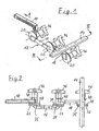
- the attachment piece shown in Figure 1 comprises a trained as a plug rail connector 10 which is inserted in the direction of arrow A in a suitable guide or socket on the bearing surface of a surgical table or the like, a generally designated 12 articulated arm and a rail 14 through the articulated arm 12 is pivotally connected to the connector 10 and which is intended for clamping an accessory, such as a head plate for the head of a patient.
- a plug rail connector 10 which is inserted in the direction of arrow A in a suitable guide or socket on the bearing surface of a surgical table or the like
- a generally designated 12 articulated arm and a rail 14 through the articulated arm 12 is pivotally connected to the connector 10 and which is intended for clamping an accessory, such as a head plate for the head of a patient.
- the articulated arm 12 has two rod-shaped articulated levers 16, 18, which are connected to each other via a first joint 20.
- the first articulated lever 16 is connected via a further joint 20 with the connecting part 10, while the other end of the second articulated lever 18 is connected via a further joint 20 with the rail 14.
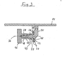
- All three joints 20 have a same structure, which will be explained in more detail with reference to FIG 3.
- Each joint comprises a first toothed disc 22, which is formed integrally with a co-axial to the hinge axis, formed as a clamping screw hinge pin 24.
- the hinge pin has a smooth cylindrical shaft portion 26 and a smaller diameter threaded portion 28.
- the toothed disc 22 has a circumferential at its radially outer edge of the toothed ring or ring gear 30 with an axially directed toothing 32 ( Figure 2).
- a projection 34 On its side facing away from the sprocket toothed wheel 22 is connected to a projection 34 which carries the rail 40, which is directed with its longitudinal direction parallel to the hinge axis 36.
- the toothed disc 22 is associated with a second toothed disc 38, which also has a toothed ring or toothed ring 30 with axially directed toothing on its toothed disc 22 facing axially normal surface.
- the toothed disc 38 On its side facing away from the ring gear 30, the toothed disc 38 is connected to a bushing 40, which receives the shaft portion 26 of the hinge pin 24 in a bore 42.
- a cavity is formed by the axially projecting sprockets 30, in which a plate spring 44 is located, which axially urges the toothed discs 22 and 38 apart.
- nut 48 On the threaded portion 28 of the hinge pin 24 connected in the form of a rotary handle 46 nut 48 is screwed, with which the two toothed discs 22 and 38 can be clamped against each other.
- a thrust bearing 50 is disposed between the sleeve 40 and the nut 48.
- the formation is made such that the first articulated lever 16 is connected at each of its ends with a hinge pin 24 carrying a toothed disc 22.
- the second articulated lever 18, however, is in each case connected to a toothed washer 38 carrying a bushing 40.
- the connecting piece 10 is connected to a sleeve 40 bearing pulley, while the rail 14 is in turn connected to a hinge pin 24 bearing pulley 22, as has already been explained with reference to FIG 3.
- This arrangement results in that all three knobs 46 are on the same side of the mounting piece, as shown in Figures 1 and 2, so that the adjustment of the sections of the actuating piece in the three joints can be conveniently done from the same position of the operator without this must embrace.
Landscapes
- Engineering & Computer Science (AREA)
- General Engineering & Computer Science (AREA)
- Mechanical Engineering (AREA)
- Health & Medical Sciences (AREA)
- Life Sciences & Earth Sciences (AREA)
- General Health & Medical Sciences (AREA)
- Public Health (AREA)
- Veterinary Medicine (AREA)
- Animal Behavior & Ethology (AREA)
- Biomedical Technology (AREA)
- Accommodation For Nursing Or Treatment Tables (AREA)
- Pivots And Pivotal Connections (AREA)
- Supports Or Holders For Household Use (AREA)
Claims (6)
- Pièce de fixation destinée à tenir des accessoires au niveau de la surface porteuse d'une table d'opération ou analogue, ladite pièce de fixation comportant une pièce de raccordement (10) destinée à relier la pièce de fixation à la surface porteuse, un rail profilé (14) destiné à fixer un accessoire, et un bras articulé (12) qui relie le rail profilé (14) à la pièce de raccordement (10) et qui comporte au moins deux leviers articulés (16, 18) qui sont reliés entre eux ainsi qu'à la pièce de raccordement (10) d'une part et au rail profilé (14) à chaque fois par une articulation blocable (20), les axes d'articulation étant parallèles entre eux, et chaque articulation comportant deux disques dentés coaxiaux (22, 38) qui comportent chacun sur leurs surfaces dirigées l'une vers l'autre une couronne dentée (30) coaxiale à l'axe d'articulation, chaque disque denté (22, 38) étant relié rigidement à l'une des pièces (10, 16, 18, 14) qui doivent être reliées entre elles par une articulation (20) et les disques dentés (22, 38) de chaque articulation pouvant être serrés l'un contre l'autre par une vis de serrage (24) coaxiale à l'axe d'articulation respectif et dotée d'un écrou (48) afin d'amener en prise l'une avec l'autre les couronnes dentées (30) des disques dentés (22, 38) serrés l'un contre l'autre, caractérisée en ce que l'un des disques dentés (22) de chaque articulation est relié rigidement à la vis de serrage (24) tandis que l'autre disque denté (38) est relié rigidement à une douille (40) qui comporte un perçage traversant (42) destiné au boulon fileté (24) et sur la surface d'extrémité de laquelle vient s'appuyer l'écrou (48) qui peut se visser sur le boulon fileté (24) et qui est relié à une poignée tournante (46), et en ce que les disques dentés (22, 38) sont précontraints axialement en éloignement l'un de l'autre par un moyen élastique (44) disposé entre eux.
- Pièce de fixation selon la revendication 1, caractérisée en ce que la pièce (10, 16, 18, 14), reliée au disque denté respectif (22, 38), est fixée au côté, opposé à la couronne dentée (30), du disque denté (22, 38).
- Pièce de fixation selon la revendication 1 ou 2, caractérisée en ce qu'un palier axial (50) est disposé entre l'écrou (48) et la surface d'extrémité axiale de la douille (40).
- Pièce de fixation selon l'une des revendications 1 à 3, caractérisée en ce qu'un premier levier articulé porte à chacune de ses extrémités un disque denté (22) doté d'un boulon fileté (24), et en ce que le deuxième levier articulé (18) porte à chacune de ses extrémités un disque denté (38) doté d'une douille (40).
- Pièce de fixation selon l'une des revendications 1 à 4, caractérisée en ce que la pièce de raccordement (10) est conformée en rail à enficher qui est enfichable dans un guide ménagé au niveau de la surface porteuse de la table d'opération, et qui est arrêtable dans le guide.
- Pièce de fixation selon l'une des revendications 1 à 5, caractérisée en ce que la direction longitudinale du rail profilé (14) est parallèle aux axes d'articulation (36).
Applications Claiming Priority (2)
| Application Number | Priority Date | Filing Date | Title |
|---|---|---|---|
| DE20209387U | 2002-06-17 | ||
| DE20209387U DE20209387U1 (de) | 2002-06-17 | 2002-06-17 | Befestigungsstück zur Halterung von Zubehörteilen an der Lagerungsfläche eines Operationstisches |
Publications (2)
| Publication Number | Publication Date |
|---|---|
| EP1374823A1 EP1374823A1 (fr) | 2004-01-02 |
| EP1374823B1 true EP1374823B1 (fr) | 2006-06-07 |
Family
ID=7972263
Family Applications (1)
| Application Number | Title | Priority Date | Filing Date |
|---|---|---|---|
| EP03008286A Expired - Lifetime EP1374823B1 (fr) | 2002-06-17 | 2003-04-09 | Elément de fixation pour attacher des accessoires au surface de couchage d'une table d'opération |
Country Status (3)
| Country | Link |
|---|---|
| EP (1) | EP1374823B1 (fr) |
| AT (1) | ATE328565T1 (fr) |
| DE (2) | DE20209387U1 (fr) |
Families Citing this family (2)
| Publication number | Priority date | Publication date | Assignee | Title |
|---|---|---|---|---|
| DE202011052144U1 (de) | 2011-11-29 | 2013-03-04 | Schmitz u. Söhne GmbH & Co. KG | Schwenkgelenk |
| EP3620148B1 (fr) * | 2018-08-28 | 2021-04-21 | KaVo Dental GmbH | Unité de traitement dentaire dotée d'une partie articulée, d'un bras pivotant et d'un dispositif de freinage |
Family Cites Families (3)
| Publication number | Priority date | Publication date | Assignee | Title |
|---|---|---|---|---|
| US1266367A (en) * | 1915-05-08 | 1918-05-14 | Ira H Wilson | Adjustable support or rest. |
| US4592526A (en) * | 1981-08-24 | 1986-06-03 | Jacob Kobelt | Adjustable holding device |
| AU7363598A (en) * | 1997-04-28 | 1998-11-24 | Taylor & Wang, Inc. | A fully adjustable and collapsible multi-articulated support platform |
-
2002
- 2002-06-17 DE DE20209387U patent/DE20209387U1/de not_active Expired - Lifetime
-
2003
- 2003-04-09 DE DE50303645T patent/DE50303645D1/de not_active Expired - Lifetime
- 2003-04-09 AT AT03008286T patent/ATE328565T1/de not_active IP Right Cessation
- 2003-04-09 EP EP03008286A patent/EP1374823B1/fr not_active Expired - Lifetime
Also Published As
| Publication number | Publication date |
|---|---|
| EP1374823A1 (fr) | 2004-01-02 |
| DE20209387U1 (de) | 2002-08-29 |
| ATE328565T1 (de) | 2006-06-15 |
| DE50303645D1 (de) | 2006-07-20 |
Similar Documents
| Publication | Publication Date | Title |
|---|---|---|
| DE3107502A1 (de) | Lenkstangen-einstellvorrichtung | |
| DE19647742C2 (de) | Einrichtungs-Anziehvorrichtung für unverlierbare Schrauben | |
| DE69506172T2 (de) | Handdrehwerkzeug | |
| EP1671527B1 (fr) | Elément de liason | |
| EP0508331A2 (fr) | Element de fermeture en particulier pour colliers | |
| EP2685204B1 (fr) | Dispositif de montage d'un dispositif de visée sur une arme à feu de poing | |
| DE2405262A1 (de) | Spannschraube | |
| DE3039215C1 (de) | Einstellvorrichtung fuer lageverstellbar verbundene Bauteile,insbesondere Treibriemenspannvorrichtung mit Spannlasche | |
| EP0716898A1 (fr) | Scie sauteuse avec plaque de base inclinable | |
| EP0421281A1 (fr) | Dispositif pour le réglage de voie d'une véhicule, notamment d'un tracteur agricole | |
| DE102008029632B4 (de) | Verbindungsmechanismus | |
| EP1374823B1 (fr) | Elément de fixation pour attacher des accessoires au surface de couchage d'une table d'opération | |
| DE69218972T2 (de) | Dynamometrische schraube oder mutter | |
| DE3436710C2 (de) | Rohrschelle | |
| DE8804852U1 (de) | Als Schraubenschlüssel verwendbare Vorrichtung zum Sprengen einer Schraubenmutter | |
| DE4316797C2 (de) | Gelenk insbesondere an Percussions-Musikinstrumenten | |
| DE19612752C2 (de) | Selbstklemmender Spannschlüssel | |
| DE2929984A1 (de) | Felgenbremse | |
| DE602005000489T2 (de) | Hebelbetätigbare Klemmvorrichtung zum Befestigen von einem Anti-Gleit-System an der Felge von einem Fahrzeugrad | |
| EP0452625B1 (fr) | Fixation réglable d'une rotule sur une barre pour une timonerie de direction de véhicules automobiles | |
| DE19925045B4 (de) | Hilfsvorrichtung zur Montage bzw. Demontage von Fahrzeugrädern | |
| DE102009002155A1 (de) | Verbindung zur lösbaren Befestigung eines Gesenkes oder einer Positioniereinrichtung an einer Crimpzange sowie Positioniereinrichtung und Crimpzange mit einer solchen Verbindung | |
| DE102023118410B3 (de) | Sicherungsring für Schraubgerät, Reaktionskraftübertragungselement für Schraubgerät sowie Schraubgerät | |
| EP4181804A1 (fr) | Dispositif de fixateur externe pour fractures osseuses | |
| DE19612751C2 (de) | Selbstklemmender Spannschlüssel |
Legal Events
| Date | Code | Title | Description |
|---|---|---|---|
| PUAI | Public reference made under article 153(3) epc to a published international application that has entered the european phase |
Free format text: ORIGINAL CODE: 0009012 |
|
| AK | Designated contracting states |
Kind code of ref document: A1 Designated state(s): AT BE BG CH CY CZ DE DK EE ES FI FR GB GR HU IE IT LI LU MC NL PT RO SE SI SK TR |
|
| AX | Request for extension of the european patent |
Extension state: AL LT LV MK |
|
| 17P | Request for examination filed |
Effective date: 20040217 |
|
| AKX | Designation fees paid |
Designated state(s): AT BE BG CH CY CZ DE DK EE ES FI FR GB GR HU IE IT LI LU MC NL PT RO SE SI SK TR |
|
| 17Q | First examination report despatched |
Effective date: 20041004 |
|
| GRAP | Despatch of communication of intention to grant a patent |
Free format text: ORIGINAL CODE: EPIDOSNIGR1 |
|
| GRAS | Grant fee paid |
Free format text: ORIGINAL CODE: EPIDOSNIGR3 |
|
| GRAA | (expected) grant |
Free format text: ORIGINAL CODE: 0009210 |
|
| AK | Designated contracting states |
Kind code of ref document: B1 Designated state(s): AT BE BG CH CY CZ DE DK EE ES FI FR GB GR HU IE IT LI LU MC NL PT RO SE SI SK TR |
|
| PG25 | Lapsed in a contracting state [announced via postgrant information from national office to epo] |
Ref country code: CZ Free format text: LAPSE BECAUSE OF FAILURE TO SUBMIT A TRANSLATION OF THE DESCRIPTION OR TO PAY THE FEE WITHIN THE PRESCRIBED TIME-LIMIT Effective date: 20060607 Ref country code: SK Free format text: LAPSE BECAUSE OF FAILURE TO SUBMIT A TRANSLATION OF THE DESCRIPTION OR TO PAY THE FEE WITHIN THE PRESCRIBED TIME-LIMIT Effective date: 20060607 Ref country code: RO Free format text: LAPSE BECAUSE OF FAILURE TO SUBMIT A TRANSLATION OF THE DESCRIPTION OR TO PAY THE FEE WITHIN THE PRESCRIBED TIME-LIMIT Effective date: 20060607 Ref country code: IE Free format text: LAPSE BECAUSE OF FAILURE TO SUBMIT A TRANSLATION OF THE DESCRIPTION OR TO PAY THE FEE WITHIN THE PRESCRIBED TIME-LIMIT Effective date: 20060607 Ref country code: NL Free format text: LAPSE BECAUSE OF FAILURE TO SUBMIT A TRANSLATION OF THE DESCRIPTION OR TO PAY THE FEE WITHIN THE PRESCRIBED TIME-LIMIT Effective date: 20060607 Ref country code: FI Free format text: LAPSE BECAUSE OF FAILURE TO SUBMIT A TRANSLATION OF THE DESCRIPTION OR TO PAY THE FEE WITHIN THE PRESCRIBED TIME-LIMIT Effective date: 20060607 Ref country code: IT Free format text: LAPSE BECAUSE OF FAILURE TO SUBMIT A TRANSLATION OF THE DESCRIPTION OR TO PAY THE FEE WITHIN THE PRESCRIBED TIME-LIMIT;WARNING: LAPSES OF ITALIAN PATENTS WITH EFFECTIVE DATE BEFORE 2007 MAY HAVE OCCURRED AT ANY TIME BEFORE 2007. THE CORRECT EFFECTIVE DATE MAY BE DIFFERENT FROM THE ONE RECORDED. Effective date: 20060607 Ref country code: SI Free format text: LAPSE BECAUSE OF FAILURE TO SUBMIT A TRANSLATION OF THE DESCRIPTION OR TO PAY THE FEE WITHIN THE PRESCRIBED TIME-LIMIT Effective date: 20060607 |
|
| REG | Reference to a national code |
Ref country code: GB Ref legal event code: FG4D Free format text: NOT ENGLISH |
|
| REG | Reference to a national code |
Ref country code: CH Ref legal event code: EP |
|
| REG | Reference to a national code |
Ref country code: CH Ref legal event code: NV Representative=s name: SCHNEIDER FELDMANN AG PATENT- UND MARKENANWAELTE |
|
| REG | Reference to a national code |
Ref country code: IE Ref legal event code: FG4D Free format text: LANGUAGE OF EP DOCUMENT: GERMAN |
|
| REF | Corresponds to: |
Ref document number: 50303645 Country of ref document: DE Date of ref document: 20060720 Kind code of ref document: P |
|
| GBT | Gb: translation of ep patent filed (gb section 77(6)(a)/1977) |
Effective date: 20060808 |
|
| PG25 | Lapsed in a contracting state [announced via postgrant information from national office to epo] |
Ref country code: DK Free format text: LAPSE BECAUSE OF FAILURE TO SUBMIT A TRANSLATION OF THE DESCRIPTION OR TO PAY THE FEE WITHIN THE PRESCRIBED TIME-LIMIT Effective date: 20060907 |
|
| PG25 | Lapsed in a contracting state [announced via postgrant information from national office to epo] |
Ref country code: ES Free format text: LAPSE BECAUSE OF FAILURE TO SUBMIT A TRANSLATION OF THE DESCRIPTION OR TO PAY THE FEE WITHIN THE PRESCRIBED TIME-LIMIT Effective date: 20060918 |
|
| REG | Reference to a national code |
Ref country code: SE Ref legal event code: TRGR |
|
| PG25 | Lapsed in a contracting state [announced via postgrant information from national office to epo] |
Ref country code: PT Free format text: LAPSE BECAUSE OF FAILURE TO SUBMIT A TRANSLATION OF THE DESCRIPTION OR TO PAY THE FEE WITHIN THE PRESCRIBED TIME-LIMIT Effective date: 20061107 |
|
| NLV1 | Nl: lapsed or annulled due to failure to fulfill the requirements of art. 29p and 29m of the patents act | ||
| ET | Fr: translation filed | ||
| REG | Reference to a national code |
Ref country code: IE Ref legal event code: FD4D |
|
| PLBE | No opposition filed within time limit |
Free format text: ORIGINAL CODE: 0009261 |
|
| STAA | Information on the status of an ep patent application or granted ep patent |
Free format text: STATUS: NO OPPOSITION FILED WITHIN TIME LIMIT |
|
| 26N | No opposition filed |
Effective date: 20070308 |
|
| PG25 | Lapsed in a contracting state [announced via postgrant information from national office to epo] |
Ref country code: GR Free format text: LAPSE BECAUSE OF FAILURE TO SUBMIT A TRANSLATION OF THE DESCRIPTION OR TO PAY THE FEE WITHIN THE PRESCRIBED TIME-LIMIT Effective date: 20060908 |
|
| PG25 | Lapsed in a contracting state [announced via postgrant information from national office to epo] |
Ref country code: BG Free format text: LAPSE BECAUSE OF FAILURE TO SUBMIT A TRANSLATION OF THE DESCRIPTION OR TO PAY THE FEE WITHIN THE PRESCRIBED TIME-LIMIT Effective date: 20060907 |
|
| PG25 | Lapsed in a contracting state [announced via postgrant information from national office to epo] |
Ref country code: EE Free format text: LAPSE BECAUSE OF FAILURE TO SUBMIT A TRANSLATION OF THE DESCRIPTION OR TO PAY THE FEE WITHIN THE PRESCRIBED TIME-LIMIT Effective date: 20060607 |
|
| PG25 | Lapsed in a contracting state [announced via postgrant information from national office to epo] |
Ref country code: MC Free format text: LAPSE BECAUSE OF NON-PAYMENT OF DUE FEES Effective date: 20070430 |
|
| PG25 | Lapsed in a contracting state [announced via postgrant information from national office to epo] |
Ref country code: CY Free format text: LAPSE BECAUSE OF FAILURE TO SUBMIT A TRANSLATION OF THE DESCRIPTION OR TO PAY THE FEE WITHIN THE PRESCRIBED TIME-LIMIT Effective date: 20060607 Ref country code: LU Free format text: LAPSE BECAUSE OF NON-PAYMENT OF DUE FEES Effective date: 20070409 |
|
| PGFP | Annual fee paid to national office [announced via postgrant information from national office to epo] |
Ref country code: AT Payment date: 20090423 Year of fee payment: 7 Ref country code: SE Payment date: 20090427 Year of fee payment: 7 |
|
| PG25 | Lapsed in a contracting state [announced via postgrant information from national office to epo] |
Ref country code: HU Free format text: LAPSE BECAUSE OF FAILURE TO SUBMIT A TRANSLATION OF THE DESCRIPTION OR TO PAY THE FEE WITHIN THE PRESCRIBED TIME-LIMIT Effective date: 20061208 Ref country code: TR Free format text: LAPSE BECAUSE OF FAILURE TO SUBMIT A TRANSLATION OF THE DESCRIPTION OR TO PAY THE FEE WITHIN THE PRESCRIBED TIME-LIMIT Effective date: 20060607 |
|
| PGFP | Annual fee paid to national office [announced via postgrant information from national office to epo] |
Ref country code: BE Payment date: 20090429 Year of fee payment: 7 |
|
| BERE | Be: lapsed |
Owner name: *MAQUET G.M.B.H. & CO. K.G. Effective date: 20100430 |
|
| EUG | Se: european patent has lapsed | ||
| PG25 | Lapsed in a contracting state [announced via postgrant information from national office to epo] |
Ref country code: AT Free format text: LAPSE BECAUSE OF NON-PAYMENT OF DUE FEES Effective date: 20100409 |
|
| PG25 | Lapsed in a contracting state [announced via postgrant information from national office to epo] |
Ref country code: BE Free format text: LAPSE BECAUSE OF NON-PAYMENT OF DUE FEES Effective date: 20100430 |
|
| PG25 | Lapsed in a contracting state [announced via postgrant information from national office to epo] |
Ref country code: SE Free format text: LAPSE BECAUSE OF NON-PAYMENT OF DUE FEES Effective date: 20100410 |
|
| REG | Reference to a national code |
Ref country code: DE Ref legal event code: R082 Ref document number: 50303645 Country of ref document: DE Representative=s name: PATENTANWAELTE SCHAUMBURG, THOENES, THURN, LAN, DE |
|
| REG | Reference to a national code |
Ref country code: DE Ref legal event code: R081 Ref document number: 50303645 Country of ref document: DE Owner name: MAQUET GMBH, DE Free format text: FORMER OWNER: MAQUET GMBH & CO. KG, 76437 RASTATT, DE Effective date: 20141210 Ref country code: DE Ref legal event code: R082 Ref document number: 50303645 Country of ref document: DE Representative=s name: PATENTANWAELTE SCHAUMBURG, THOENES, THURN, LAN, DE Effective date: 20141210 Ref country code: DE Ref legal event code: R082 Ref document number: 50303645 Country of ref document: DE Representative=s name: SCHAUMBURG & PARTNER PATENTANWAELTE GBR, DE Effective date: 20141210 Ref country code: DE Ref legal event code: R082 Ref document number: 50303645 Country of ref document: DE Representative=s name: ZACCO DR. PETERS UND PARTNER, DE Effective date: 20141210 Ref country code: DE Ref legal event code: R082 Ref document number: 50303645 Country of ref document: DE Representative=s name: ZACCO PATENTANWALTS- UND RECHTSANWALTSGESELLSC, DE Effective date: 20141210 |
|
| REG | Reference to a national code |
Ref country code: DE Ref legal event code: R082 Ref document number: 50303645 Country of ref document: DE Representative=s name: SCHAUMBURG & PARTNER PATENTANWAELTE GBR, DE Ref country code: DE Ref legal event code: R082 Ref document number: 50303645 Country of ref document: DE Representative=s name: ZACCO DR. PETERS UND PARTNER, DE Ref country code: DE Ref legal event code: R082 Ref document number: 50303645 Country of ref document: DE Representative=s name: ZACCO PATENTANWALTS- UND RECHTSANWALTSGESELLSC, DE |
|
| REG | Reference to a national code |
Ref country code: DE Ref legal event code: R082 Ref document number: 50303645 Country of ref document: DE Representative=s name: ZACCO DR. PETERS UND PARTNER, DE Ref country code: DE Ref legal event code: R082 Ref document number: 50303645 Country of ref document: DE Representative=s name: ZACCO PATENTANWALTS- UND RECHTSANWALTSGESELLSC, DE |
|
| REG | Reference to a national code |
Ref country code: FR Ref legal event code: PLFP Year of fee payment: 14 |
|
| REG | Reference to a national code |
Ref country code: FR Ref legal event code: PLFP Year of fee payment: 15 |
|
| REG | Reference to a national code |
Ref country code: FR Ref legal event code: PLFP Year of fee payment: 16 |
|
| PGFP | Annual fee paid to national office [announced via postgrant information from national office to epo] |
Ref country code: GB Payment date: 20200327 Year of fee payment: 18 |
|
| PGFP | Annual fee paid to national office [announced via postgrant information from national office to epo] |
Ref country code: CH Payment date: 20200325 Year of fee payment: 18 |
|
| PGFP | Annual fee paid to national office [announced via postgrant information from national office to epo] |
Ref country code: FR Payment date: 20200320 Year of fee payment: 18 |
|
| PGFP | Annual fee paid to national office [announced via postgrant information from national office to epo] |
Ref country code: DE Payment date: 20200317 Year of fee payment: 18 |
|
| PGFP | Annual fee paid to national office [announced via postgrant information from national office to epo] |
Ref country code: IT Payment date: 20200417 Year of fee payment: 18 |
|
| REG | Reference to a national code |
Ref country code: CH Ref legal event code: PFA Owner name: MAQUET GMBH AND CO. KG, DE Free format text: FORMER OWNER: MAQUET GMBH AND CO. KG, DE |
|
| REG | Reference to a national code |
Ref country code: DE Ref legal event code: R119 Ref document number: 50303645 Country of ref document: DE |
|
| GBPC | Gb: european patent ceased through non-payment of renewal fee |
Effective date: 20210409 |
|
| PG25 | Lapsed in a contracting state [announced via postgrant information from national office to epo] |
Ref country code: LI Free format text: LAPSE BECAUSE OF NON-PAYMENT OF DUE FEES Effective date: 20210430 Ref country code: CH Free format text: LAPSE BECAUSE OF NON-PAYMENT OF DUE FEES Effective date: 20210430 Ref country code: DE Free format text: LAPSE BECAUSE OF NON-PAYMENT OF DUE FEES Effective date: 20211103 Ref country code: GB Free format text: LAPSE BECAUSE OF NON-PAYMENT OF DUE FEES Effective date: 20210409 Ref country code: FR Free format text: LAPSE BECAUSE OF NON-PAYMENT OF DUE FEES Effective date: 20210430 |
|
| PG25 | Lapsed in a contracting state [announced via postgrant information from national office to epo] |
Ref country code: IT Free format text: LAPSE BECAUSE OF NON-PAYMENT OF DUE FEES Effective date: 20200409 |
|
| PG25 | Lapsed in a contracting state [announced via postgrant information from national office to epo] |
Ref country code: IT Free format text: LAPSE BECAUSE OF NON-PAYMENT OF DUE FEES Effective date: 20210409 |