EP1374979A2 - Separationsmodul, Verfahren zu seiner Herstellung sowie seine Verwendung - Google Patents
Separationsmodul, Verfahren zu seiner Herstellung sowie seine Verwendung Download PDFInfo
- Publication number
- EP1374979A2 EP1374979A2 EP03013600A EP03013600A EP1374979A2 EP 1374979 A2 EP1374979 A2 EP 1374979A2 EP 03013600 A EP03013600 A EP 03013600A EP 03013600 A EP03013600 A EP 03013600A EP 1374979 A2 EP1374979 A2 EP 1374979A2
- Authority
- EP
- European Patent Office
- Prior art keywords
- capillaries
- ceramic
- separation module
- capillary
- bundle
- Prior art date
- Legal status (The legal status is an assumption and is not a legal conclusion. Google has not performed a legal analysis and makes no representation as to the accuracy of the status listed.)
- Withdrawn
Links
Images



Classifications
-
- B—PERFORMING OPERATIONS; TRANSPORTING
- B01—PHYSICAL OR CHEMICAL PROCESSES OR APPARATUS IN GENERAL
- B01D—SEPARATION
- B01D69/00—Semi-permeable membranes for separation processes or apparatus characterised by their form, structure or properties; Manufacturing processes specially adapted therefor
- B01D69/14—Dynamic membranes
- B01D69/141—Heterogeneous membranes, e.g. containing dispersed material; Mixed matrix membranes
-
- B—PERFORMING OPERATIONS; TRANSPORTING
- B01—PHYSICAL OR CHEMICAL PROCESSES OR APPARATUS IN GENERAL
- B01D—SEPARATION
- B01D61/00—Processes of separation using semi-permeable membranes, e.g. dialysis, osmosis or ultrafiltration; Apparatus, accessories or auxiliary operations specially adapted therefor
- B01D61/36—Pervaporation; Membrane distillation; Liquid permeation
- B01D61/362—Pervaporation
-
- B—PERFORMING OPERATIONS; TRANSPORTING
- B01—PHYSICAL OR CHEMICAL PROCESSES OR APPARATUS IN GENERAL
- B01D—SEPARATION
- B01D63/00—Apparatus in general for separation processes using semi-permeable membranes
- B01D63/02—Hollow fibre modules
- B01D63/021—Manufacturing thereof
- B01D63/022—Encapsulating hollow fibres
- B01D63/0221—Encapsulating hollow fibres using a mould
-
- B—PERFORMING OPERATIONS; TRANSPORTING
- B01—PHYSICAL OR CHEMICAL PROCESSES OR APPARATUS IN GENERAL
- B01D—SEPARATION
- B01D63/00—Apparatus in general for separation processes using semi-permeable membranes
- B01D63/02—Hollow fibre modules
- B01D63/021—Manufacturing thereof
- B01D63/0233—Manufacturing thereof forming the bundle
-
- B—PERFORMING OPERATIONS; TRANSPORTING
- B01—PHYSICAL OR CHEMICAL PROCESSES OR APPARATUS IN GENERAL
- B01D—SEPARATION
- B01D63/00—Apparatus in general for separation processes using semi-permeable membranes
- B01D63/02—Hollow fibre modules
- B01D63/031—Two or more types of hollow fibres within one bundle or within one potting or tube-sheet
-
- B—PERFORMING OPERATIONS; TRANSPORTING
- B01—PHYSICAL OR CHEMICAL PROCESSES OR APPARATUS IN GENERAL
- B01D—SEPARATION
- B01D63/00—Apparatus in general for separation processes using semi-permeable membranes
- B01D63/06—Tubular membrane modules
-
- B—PERFORMING OPERATIONS; TRANSPORTING
- B01—PHYSICAL OR CHEMICAL PROCESSES OR APPARATUS IN GENERAL
- B01D—SEPARATION
- B01D63/00—Apparatus in general for separation processes using semi-permeable membranes
- B01D63/06—Tubular membrane modules
- B01D63/061—Manufacturing thereof
-
- B—PERFORMING OPERATIONS; TRANSPORTING
- B01—PHYSICAL OR CHEMICAL PROCESSES OR APPARATUS IN GENERAL
- B01D—SEPARATION
- B01D63/00—Apparatus in general for separation processes using semi-permeable membranes
- B01D63/06—Tubular membrane modules
- B01D63/062—Tubular membrane modules with membranes on a surface of a support tube
Definitions
- the invention relates to a separation module, the bundle of ceramic, capillary Contains filter elements as well as processes for its production and a Use of the same.
- Ceramic filter elements have an asymmetrical structure, based on a porous ceramic support (support) with a thin membrane layer or several intermediate layers are applied.
- the porous ceramic gives Support the external shape and mechanical stability.
- honeycomb bodies An extruded body consisting of a large number of channels (round or angular) thin wall thicknesses are called honeycomb bodies. In such a body can accommodate large membrane areas in the smallest space. The wall thickness however, the channels are too thin to discharge permeate to the outside. Therefore be individual channels are mutually closed and used for permeate removal (EP 0 306 350, EP 0 433 582, EP 0 923 983 and WO 00/50156).
- Sheets are made by pressing, casting or extrusion.
- the thickness of the Plates is several millimeters.
- the plates can be made with profiles. Stacking the plates creates feed, retentate and permeate channels.
- Disks are made by film casting.
- the thickness of the foils is in Range from 0.5 mm ... 3 mm.
- By laminating panes Produce foil bags (DE 4 330 163).
- the capillaries are rigid and individually manageable.
- thermoplastic organic binder is used and the shaping at elevated temperature takes place (DE 694 00 874).
- Ceramic filter elements are arranged in parallel in housings. It arises Module, the connections for inlet (feed), outlet (retentate) and a connection for the filtrate (permeate) and possibly another one for rinsing liquid (sweep) contains.
- the membrane With multi-channel pipes, the membrane is on the inside of the channels applied and filtered from the inside out.
- the module shape in particular the type of fixation of the membrane elements Flow conditions and the size depend on the type of support and the special separation process.
- the tubes are installed individually in tube modules and by means of sealing rings or special sealing caps (EP 0 270 051, DE 198 46 041, EP 0 270 051) at the ends sealed to the housing.
- sealing rings or special sealing caps EP 0 270 051, DE 198 46 041, EP 0 270 051
- Methods have also been described in which the Metallic connectors are glued or soldered to the ends of the pipes (DE 4 131 407). With capillaries and hollow fibers this leads to an unacceptable high assembly costs or is not at all due to the flexibility of hollow fibers possible. Methods are required here in which a larger number of capillaries or hollow fibers are processed into a bundle.
- modules are described in which the side Bores or slots are introduced which open the permeate channels and the Allow permeate to escape to the side (US 5,855,781, EP 1 060 784).
- Filter bags are preferably provided with a central hole and on a Permeate collecting ear threaded. This gives you stacks that are assembled into modules be (DE 4 330 163).
- the present invention describes one Module using ceramic capillaries.
- the following are in this area known technical solutions:
- EP 0 938 921 describes bundles of capillaries consisting of glass-like carbon membranes put in a mold and with a resin, which with a Solid filled, poured out, the resin is subjected to an ultrasonic treatment becomes.
- EP 0 841 086 describes a module with hollow fibers which is used to achieve a mechanical stability filaments (rods) with a diameter between 0.06 mm and 3 mm, in a ratio of 0.5 times to 5 times the number of hollow fibers contains, the hollow fibers and the rods at the ends by perforated plates being held.
- rods mechanical stability filaments
- US 01/0035374 hollow fiber bundles are stabilized by the bundles are wound around spiral filaments.
- a comparable one Mechanical stabilization is the case with ceramic capillaries according to the present Invention not necessary.
- EP 0 941 759 describes a method for producing an exchanger in which put a bundle of exchanger tubes in a mold and then with one Ceramic slip filled, dried and then sintered into a plate become. In a further step, an end plate is formed in the same way. In the first plate and the end plate are parallel to the tubes header pipes for Inflow and outflow introduced. It is mentioned that such an arrangement for Membrane modules can be used, whereby no capillaries are used and no application-specific distance between the pipes is set.
- EP 0 092 839 uses a non-porous end plate through which holes are drilled, in which porous pipes are attached using special connections. The attachment is done by enamel, glass, ceramic, carbon, cement or metal.
- WO 01/87469 builds an all-ceramic module by joining ceramic Supports with a housing made of perforated end plates and cylindrical Outer sheath. In all these cases, the perforated plates are used for mechanical Fixing the tubes or capillaries. The pipes are at a fixed distance, but which has no relation to the separation process, especially not to the Amount of permeate.
- JP 61/004509 uses an aqueous slip of a mixture of glass and Ceramic powder with adjusted expansion coefficient for casting the ends porous glass membrane tube.
- JP 57166244 describes the potting smaller Tubes with a sealing material, e.g. Glass, creating an airtight faceplate arises. In both cases, sealing the ends of the capillaries and achieved mechanical fixation. However, there is no application-related defined distance set.
- the invention has for its object the described shortcomings of the prior art Technology in a separation module with reference to the parameters of the special To correct the application of optimal use of space.
- the present invention describes a separation module that has at least one Contains bundles of ceramic capillaries with a gap between the capillary tubes is set by joining, which is essential to the invention.
- the choice of The distance depends on the permeate volume that flows out without obstruction should.
- the permeate volume in turn, depends on the type of membrane and thus associated application method determined as in the following Examples 1 and 2 for the product according to the invention is explained.
- a bundle of 100 capillaries has a membrane area of 0.2 m 2 .
- the flow of a nanofiltration membrane is approx. 400l / (m 2 .h) at 20 bar. 80 l would emerge from the bundle described per hour.
- the outer shell of the bundle would contain approximately 40 slots with a length of 1 m for the permeate to flow off. If one assumes that the entire amount of permeate would come from inside the bundle, 2l / h emerge per slot. With a slot width of 0.01 mm, a permeate flow rate of 0.05 m / s would arise, which can be easily mastered.
- Typical flow velocities in pipes at 20 mbar are between 25 m / s and 50m / s. This would correspond to a slot width of 0.1 mm.
- lower flow velocities of 2 m / s to 5 m / s are expected, which would correspond to a gap width of 1 mm.
- the capillaries are made by extrusion and have an outer diameter from 0.3 mm to 10 mm, preferably 1 mm to 2.5 mm and an inner diameter from 0.3 mm to 8 mm, preferably 0.7 mm to 1.5 mm.
- the capillary bundles are produced by casting the ends with a polymer, ceramic and / or glass-containing casting compound.
- the capillaries are placed with their ends in cup-like molds, which are used for Fixing the capillaries in the bottom have holes with a defined hole spacing.
- the Cup is filled with the casting compound.
- the casting compound surrounds the capillaries completely and dries in air and at room temperature until the cup can be removed.
- the curing takes place with polymeric casting compounds e.g. With Epoxy resins at room temperature with the addition of a hardener or with one-component resins at a slightly elevated temperature.
- ceramic and / or Casting materials containing glass are cured thermally at temperatures between 150 ° C and 1600 ° C.
- the procedure is carried out at both ends of the Capillary bundle carried out simultaneously or in succession. With simultaneity a casting compound is used that is dimensionally stable after a short flash-off time. By cutting off or grinding the ends of the bundle will be those when potting partially closed channels reopened.
- the defined distance essential to the invention is in this variant by Hole pattern in the bottom plate of the mold and the overall shrinkage of the molding fixed and can vary in the range from 0.05mm to 10mm and accordingly the expected flow values of the membrane can be selected.
- the distance is set using defined of perforated plates.
- the perforated plates can be made of different materials, e.g. Plastic, metal or ceramic exist.
- the holes in the perforated plate are in the Diameter slightly larger than the diameter of the capillaries. The capillaries are inserted into the holes in the perforated plate.
- perforated plates made of plastic, metal or sintered ceramic this is done Joining using pastes containing polymer, ceramic or glass or glue.
- the perforated plates are wholly or partially in the joining material immersed or the joining material in the cavities between the perforated wall and the outside of the capillary filled.
- the Curing takes place with polymeric casting compounds e.g. with epoxy resins at room temperature with the addition of a hardener or with one-component resins for something elevated temperature.
- ceramic and / or glass-containing casting compounds curing takes place thermally at temperatures between 150 ° C and 1600 ° C.
- the procedure is carried out at the two ends of the capillary bundle simultaneously or in succession carried out. In the case of simultaneity, a pasty joining material is used, that is dimensionally stable after a short flash-off time.
- Unsintered perforated ceramic plates can also be used to manufacture the capillary bundle be used.
- the ceramic capillaries are inserted into the Perforated plate inserted. This is followed by thermal treatment at height the sintering temperature of the perforated plate, which due to its shrinkage on the Capillaries shrink on, creating a mechanically stable and tight connection arises.
- the defined distance is determined by the hole pattern in the perforated plate fixed and can vary in the range from 0.1 mm to 10 mm and according to that expected flow values of the membrane can be selected.
- a defined distance between the ceramic Capillaries adjusted in that the capillaries with strip-shaped films curable material can be wound up.
- the winding can also be done with unsintered ceramic capillaries and unsintered ones ceramic foils. In this case it becomes firm and dense Connection achieved by co-firing at temperatures up to 1700 ° C.
- the defined distance is determined by the thickness of the joining film and the Wrapping algorithm determines and can vary in the range of 0.1 mm and 1 mm and selected according to the expected flow values of the membrane.
- capillary bundles which are typical a diameter between 10 mm and 250 mm, preferably between 20 mm and 50 mm.
- the distance between the capillaries in the bundle is ⁇ 3 mm.
- One module preferably becomes several of these capillary bundles produced in this way connected in parallel.
- the housing can be made of stainless steel and the seal feed and permeation space through an elastomer O-ring.
- housing made of ceramic.
- the housing parts are then shaped via Casting and / or by mechanical processing of ceramic levers in leather-hard Status.
- the connection of housing and capillary bundle at the same time The sintered housing parts separate the feed and permeation spaces by joining with ceramic or glass-containing slip, paste or adhesive with subsequent thermal treatment at temperatures between 500 ° C and 1400 ° C.
- gas separation or Pervaporation is a membrane layer on the porous ceramic capillaries necessary.
- the membrane layer can fundamentally both on the inside of the capillaries, as well as on their outside.
- the membrane layers are made by various processes of slip coating, sol-gel technology or the crystallization from solution. In all cases one closes thermal treatment (baking) of the membrane layer at temperatures > 300 ° C.
- thermal treatment baking
- plastic-containing casting compounds perforated plates or joining foils plastic is a thermal treatment of the capillary bundle in such high temperatures not possible.
- the membrane is in front of the Joined to the capillary bundle.
- Sintered porous capillaries 9 with an outer diameter of 3.6 mm and one Inside diameter of 2.0 mm, consisting of 99.8% aluminum oxide, will be on cut a length of 350 mm.
- For the casting compound is a Porcelain slip containing high alumina, the main components of which are 52% Clay, 11% quartz, 13% feldspar, 26% aluminum oxide, 31% water (based on Solid), 0.5% water glass (based on solid) and 0.2% soda (based on Solid).
- the casting mold 8 used for the casting consists of mold plaster. In the bottom of the mold there are 19 holes with a diameter of 3.6 mm and a depth of 8 mm (Fig. 3a). The inside diameter of the mold is 27 mm.
- the capillaries 9 are inserted into the holes in the mold base (Fig. 3b) and in a drum mill according to the offset specification Slurry 10 produced is manually and continuously filled into the mold (Fig. 3c).
- the unmolded end plate 11 is in the leather-hard state possible with a residual moisture of 12-15% (Fig. 3d). Then the White drying up to a residual moisture of 2%.
- Adding the second side of the Capillary bundle is done in the same way. Then be dried on Capillary bundle blank the capillaries protruding on the front sides with a Cut off diamond cutting disc and plastered the end faces (Fig. 3e).
- the subsequent firing cycle consists of the following stages: 1) heating phase, 2) Oxidizing cleaning phase, 3) reducing focus fire phase, 4) oxidizing Cooling phase.
- the bundle is sintered horizontally at a sintering temperature of 1470 ° C and a holding time of 45 min. Post-processing of the bundle with the sintered stimulation plate 12 is not required (FIG. 3f).
- the perforated plates (Fig. 4) at the ends of the capillary bundle consist of dense aluminum oxide. They have an outer diameter of 32 mm and 55 holes with a diameter of 2.9 mm evenly arranged in segments. Both materials have a linear thermal expansion coefficient of (7.6-7.8) 10 -6 K -1 .
- aluminum oxide powder with an average grain size of 0.8 ⁇ m, doped with MgO, is extruded rigid plastic.
- the aluminum oxide To plasticize the aluminum oxide, it is placed in a twin-screw kneader together with 5% water-soluble cellulose, 3% nonionic surfactant, 2% wax and 10% water. After a kneading time of approx. 2 h, the rigid plastic mass is extruded on a vacuum screw extruder as a perforated strand with a length of 750 mm.
- the tool for the perforated strand consists of a sleeve with an inside diameter of 35.5 mm and 55 pins with a diameter of 3.2 mm.
- the moldings are dried in a climatic chamber, starting at 28 ° C and 100% humidity. At this point in time, the moisture of the moldings is still 10%.
- Sintered porous capillaries 9 with an outer diameter of 1.4 mm and one Inner diameter of 1.0 mm, consisting of 99.8 aluminum oxide are made on a Cut length of 350 mm. These cut pieces are made as in Figure 7 shown, pressed in parallel in soft ceramic film strips 13. This ceramic Film strips 13 have a thickness of 2 mm. Then the combination of capillaries 9 and strips 13 wound into a bundle, as in Figure 8 shown. Due to the offset attachment of the film strips 13 arise between the capillaries 9 separated by baffles 6 well defined chambers Size, so that the module can later be flowed through in a meandering shape. As a further processing step, the ends are cast, the is carried out analogously to Example 3, the mold bottom being dispensed with can, because the capillaries of the bundle are kept at the correct distance by the strips become.
Landscapes
- Chemical & Material Sciences (AREA)
- Chemical Kinetics & Catalysis (AREA)
- Engineering & Computer Science (AREA)
- Manufacturing & Machinery (AREA)
- Water Supply & Treatment (AREA)
- Dispersion Chemistry (AREA)
- Separation Using Semi-Permeable Membranes (AREA)
Abstract
Description
- Fig. 1:
- Prinzipieller asymmetrischer Aufbau rohrförmiger Filterelemente mit Träger (T), Zwischenschicht (ZS) und Membran (M) für a) Innenbeschichtung und b) Außenbeschichtung.
- Fig. 2:
- Schematische Darstellung eines Separationsmoduls mit den Anschlüssen für Feed (1), Retentat (2), Permeat (3) und Sweep (4) sowie den Filterelementen (5), Umlenkplatten (6) zum Erzeugen einer Zwangsströmung und dem Gehäuse (7).
- Fig. 3:
- Prinzip des Fügens mit einer Gießmasse (Anspruch 14) a) Gipsform (8) b) Gipsform (8) mit Kapillaren (9) c) Gipsform (8) mit Kapillaren (9) und ein-gefülltem Gießschlicker (10) d) Kapillar-Bündel mit ungesinterter Stimplatte (11) e) Kapillar-Bündel mit ungesinterter Stimplatte (11) beschnitten f) Kapillar-Bündel mit gesinterter Stimplatte (12).
- Fig. 4:
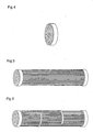
- Lochscheibe (Ansprüche 15 bis 17)
- Fig. 5:
- Separationsmodul hergestellt nach einem der Ansprüche 15 bis 17.
- Fig. 6:
- Separationsmodul hergestellt nach einem der Ansprüche 15 bis 17 mit Abstandshaltern nach Anspruch 8.
- Fig. 7:
- Kapillaren in Folienstreifen eingedrückt (Anspruch 19) a) Draufsicht b) Seitenansicht.
- Fig. 8:
- Kapillarbündel nach dem Aufwickeln schematisch im Schnitt dargestellt (Ansprüche 8, 18 und 19).
- 1
- Feed (Zufuhr)
- 2
- Retentat
- 3
- Permeat
- 4
- Sweep (Spülflüssigkeit)
- 5
- Filterelement
- 6
- Umlenkplatte
- 7
- Gehäuse
- 8
- Gipsform
- 9
- Kapillare
- 10
- Gießschlicker
- 11
- ungesinterte Stimplatte
- 12
- gesinterte Stirnplatte
- 13
- Folienstreifen
Claims (23)
- Separationsmodul, dadurch gekennzeichnet, dass er mindestens ein Bündel keramischer Kapillaren (9) enthält, bei dem zur Steuerung des Stofftransportes und der Strömung im Separationsmodul ein bestimmter Abstand zwischen den Kapillaren (9) durch Fügen eingestellt ist.
- Separationsmodul, insbesondere nach Anspruch 1, wenigstens aufweisend mindestens ein Bündel keramischer permeabler Kapillaren, die an ihren Enden durch eine Lochscheibe zusammengefasst sind und ein das Kapillarbündel umgebendes Gehäuse mit Zu und/oder Ableitungen zu dem Kapillarinneren für einen ersten Stoffstrom und mit Zu- und/oder Ableitungen für einen zweiten Stoffstrom zu dem Kapillarzwischenraum, dadurch gekennzeichnet der Abstand zwischen den Kapillaren mittels Distanzstücken (6) konstant gehalten ist.
- Separationsmodul nach Anspruch 1 oder 2, dadurch gekennzeichnet, dass die Kapillarbündel Kapillaren (9) mit einem Außendurchmesser im Bereich von 0,3 mm bis 10 mm, vorzugsweise 1 mm bis 2,5 mm und einem Innendurchmesser von 0,1 mm bis 8 mm, vorzugsweise 0,7 mm bis 1,5 mm enthält.
- Separationsmodul nach einem der Ansprüche 1 bis 3, dadurch gekennzeichnet, dass der Abstand der Kapillaren (9) im Kapillarbündel ≤ 10 mm, vorzugsweise < 5 mm beträgt.
- Separationsmodul nach einem der Ansprüche 1 bis 4, dadurch gekennzeichnet, dass der Abstand zwischen den Kapillaren (9) im Bündel abhängig vom Permeatfluss und Permeatmedium eingestellt ist.
- Separationsmodul nach einem der Ansprüche 1 bis 5, dadurch gekennzeichnet, dass die Kapillarbündel einen Durchmesser zwischen 10 mm und 250 mm, vorzugsweise zwischen 20 mm und 50 mm aufweisen.
- Separationsmodul nach einem der Ansprüche 1 bis 6, dadurch gekennzeichnet, dass die Kapillaren (9) auf der Innenseite eine dünne, trennaktive Membran (M) aufweisen.
- Separationsmodul nach einem der Ansprüche 1 bis 6, dadurch gekennzeichnet, dass die Kapillaren (9) auf der Außenseite eine dünne, trennaktive Membran (M) aufweisen.
- Separationsmodul nach einem der Ansprüche 1 bis 8, gekennzeichnet durch eingebaute Abstandshalter als Umlenkplatten (6) zur Steuerung der Strömung im Raum zwischen den Kapillaren (9).
- Separationsmodul nach einem der Ansprüche 1 bis 9, dadurch gekennzeichnet, dass mehrere Kapillarbündel in einem Gehäuse parallelgeschaltet sind.
- Separationsmodul nach Anspruch 10, dadurch gekennzeichnet, dass das Gehäuse aus Edelstahl besteht und die Abdichtung des Lochscheibenumfang zur Trennung von Feed- und Permeationsraum durch einen Elastomer-O-Ring, eine Graphitdichtung oder eine Dichtungsmasse erfolgt.
- Separationsmodul nach Anspruch 10, dadurch gekennzeichnet, dass das Gehäuse aus Keramik besteht und Abdichtung des Lochscheibenumfang zur Trennung von Feed- und Permeationsraum an Fügestellen durch keramikoder glashaltigem Schlicker, Paste oder Kleber erfolgt.
- Separationsmodul nach einem der Ansprüche 1 bis 12 zum Einsatz als Membranreaktor, dadurch gekennzeichnet, dass die einzelnen Kapillaren mit einem Katalysator beschichtet sind, selber Katalysator sind oder der Katalysator sich an anderer Stelle im Modul befindet.
- Verfahren zur Herstellung eines Separationsmoduls nach einem der Ansprüche 1 bis 13, dadurch gekennzeichnet, dass das Fügen erfolgt, indem vorgeformte Kapillaren (9) untereinander parallel und in einem durch Erfordernisse des Stofftransportes und der Strömung im späteren Separationsmodul bestimmten Abstand in Bündelform fixiert und zumindest in den Ebenen der beiden Stirnflächen des künftigen Separationsmoduls stoffschlüssig verbunden werden.
- Verfahren nach Anspruch 14, dadurch gekennzeichnet, dass gesinterte keramische Kapillaren (9) in Bohrungen am Boden einer Form (8) gestellt werden, diese Form (8) mit einer polymer-, keramik- und/oder glashaltigen Gießmasse (10) ausgegossen wird und nach dem Entformen die überstehenden Ende der Kapillaren (9) abgetrennt werden.
- Verfahren nach Anspruch 14, dadurch gekennzeichnet, dass gesinterte keramische Kapillaren in Lochscheiben aufgesteckt und die Fugen zwischen beiden unter Verwendung von polymer-, keramik- oder glashaltiger Schlicker, Pasten oder Kleber abgedichtet werden.
- Verfahren nach Anspruch 14, dadurch gekennzeichnet, dass gesinterte keramische Kapillaren in ungesinterte keramische Lochscheiben gesteckt und durch Aufschrumpfen der Lochscheibe fest verbunden werden.
- Verfahren nach Anspruch 14, dadurch gekennzeichnet, dass ungesinterte keramische Kapillaren in ungesinterte keramische Lochscheiben gesteckt und durch Co-firing fest verbunden werden.
- Verfahren nach Anspruch 14, dadurch gekennzeichnet, dass gesinterte keramische Kapillaren (9) mit wenigstens einem Streifen (13) polymer-, keramik- und/oder glashaltiger Folie, Geflechte oder Gewebe aufgewickelt und durch Aufschrumpfen beim Aushärten der Folie fest verbunden werden.
- Separationsmodul nach Anspruch 14, dadurch gekennzeichnet, dass ungesinterte keramische Kapillaren (9) mit wenigstens einem Streifen (13) keramik- und/oder glashaltiger Folie, Geflechte oder Gewebe aufgewickelt und durch Co-firing fest verbunden werden.
- Verfahren nach einem der Ansprüche 14 bis 20 zur Herstellung von Kapillarbündeln nach Anspruch 6 oder 7, dadurch gekennzeichnet, dass im Fall eines vollkeramischen Kapillarbündels die Beschichtung mit der trennaktiven Membran (M) nach Fertigstellung des Kapillarbündels in einem Schritt erfolgen kann.
- Verfahren nach einem der Ansprüche 14 bis 20 zur Herstellung von Kapillarbündeln nach Anspruch 6 oder 7, dadurch gekennzeichnet, dass bei Verwendung eines nichtkeramischen Bestandteils zur Herstellung des Kapillarbündels die Kapillaren vor Einbau in den Modul mit einer trennaktiven Membran (M) beschichtet werden.
- Verfahren zur Verwendung eines Separationsmoduls nach einem der Ansprüche 1 bis 15, dadurch gekennzeichnet, dass er in Membranverfahren eingesetzt wird, in denen ein Vakuum auf der Permeatseite (3) angelegt wird.
Applications Claiming Priority (2)
| Application Number | Priority Date | Filing Date | Title |
|---|---|---|---|
| DE10227721 | 2002-06-21 | ||
| DE10227721A DE10227721B4 (de) | 2002-06-21 | 2002-06-21 | Verfahren zur Herstellung eines Bündels keramischer Kapillaren für ein Separationsmodul |
Publications (2)
| Publication Number | Publication Date |
|---|---|
| EP1374979A2 true EP1374979A2 (de) | 2004-01-02 |
| EP1374979A3 EP1374979A3 (de) | 2005-03-30 |
Family
ID=29716577
Family Applications (1)
| Application Number | Title | Priority Date | Filing Date |
|---|---|---|---|
| EP03013600A Withdrawn EP1374979A3 (de) | 2002-06-21 | 2003-06-16 | Separationsmodul, Verfahren zu seiner Herstellung sowie seine Verwendung |
Country Status (6)
| Country | Link |
|---|---|
| US (1) | US8021619B2 (de) |
| EP (1) | EP1374979A3 (de) |
| JP (1) | JP4391141B2 (de) |
| DE (1) | DE10227721B4 (de) |
| PL (1) | PL206788B1 (de) |
| RU (1) | RU2338583C2 (de) |
Cited By (3)
| Publication number | Priority date | Publication date | Assignee | Title |
|---|---|---|---|---|
| WO2005070523A3 (de) * | 2004-01-27 | 2006-02-02 | Koch Membrane Systems Gmbh | Membranfiltereinheit und verfahren zur herstellung der membranfiltereinheit |
| WO2011101295A1 (de) | 2010-02-22 | 2011-08-25 | 3C Membrane Ag | Verfahren zum herstellen eines membranmoduls sowie membranmodul |
| EP2481474A1 (de) * | 2011-01-27 | 2012-08-01 | Filtrox AG | Dichtungsanordnung für stabförmige keramische Filterelemente |
Families Citing this family (30)
| Publication number | Priority date | Publication date | Assignee | Title |
|---|---|---|---|---|
| FI117179B (fi) * | 2004-01-23 | 2006-07-14 | Environics Oy | Kaasukromatografi |
| JP5023430B2 (ja) * | 2004-03-17 | 2012-09-12 | 東レ株式会社 | 中空糸膜モジュールおよびその製造方法 |
| EP1766287B1 (de) | 2004-06-15 | 2012-04-11 | Data Cloak LLC | Elektro-optische hochleistungs-led-anordnung |
| DE102005008900B4 (de) * | 2005-02-26 | 2008-02-14 | Fraunhofer-Gesellschaft zur Förderung der angewandten Forschung e.V. | Verfahren zur Herstellung gasdichter und temperaturbelastbarer Module mit keramischen Hohlfaser- oder Kapillarmembranen |
| US7648566B2 (en) * | 2006-11-09 | 2010-01-19 | General Electric Company | Methods and apparatus for carbon dioxide removal from a fluid stream |
| US7966829B2 (en) * | 2006-12-11 | 2011-06-28 | General Electric Company | Method and system for reducing CO2 emissions in a combustion stream |
| JP5148578B2 (ja) * | 2007-03-15 | 2013-02-20 | 三菱重工業株式会社 | 脱水システム |
| JP2011519310A (ja) * | 2008-04-28 | 2011-07-07 | コーニング インコーポレイテッド | 液体を濾過するためのモノリス隔膜モジュール |
| DE102009038673A1 (de) * | 2009-08-24 | 2011-03-03 | Dritte Patentportfolio Beteiligungsgesellschaft Mbh & Co.Kg | Flechten der Hohlfaser bei Stoff-(Energie) Transportvorgängen in Austauscher-(Hohlfaser-)Modulen |
| DE102009038814A1 (de) * | 2009-08-31 | 2011-03-10 | Uhde Gmbh | Verfahren zur Pottung keramischer Kapillarmembranen |
| PL2327466T3 (pl) * | 2009-11-12 | 2014-11-28 | Novomatic Ag | Urządzenie oczyszczające powietrze do usuwania zanieczyszczeń powietrza ze strumienia powietrza |
| KR101175986B1 (ko) | 2009-12-31 | 2012-08-22 | 한국에너지기술연구원 | 무기질 중공사 번들 및 그 제조방법 |
| US9932648B2 (en) | 2011-10-31 | 2018-04-03 | Ut-Battelle, Llc | Flow-through pretreatment of lignocellulosic biomass with inorganic nanoporous membranes |
| US20140263034A1 (en) * | 2011-10-31 | 2014-09-18 | Ut-Battelle, Llc | Inorganic nanoporous membranes for high temperature pretreatment of lignocellulosic biomass |
| JP2015506269A (ja) * | 2011-12-22 | 2015-03-02 | リファイン テクノロジー エルエルシーRefine Technology,Llc | 中空繊維のカートリッジおよび構成要素ならびにそれらの構築方法 |
| RU2488089C1 (ru) * | 2012-03-14 | 2013-07-20 | Общество С Ограниченной Ответственностью Научно-Техническая Фирма "Бакс" | Пробоотборник для отбора сероводорода из расплава серы |
| RU2496560C1 (ru) * | 2012-04-10 | 2013-10-27 | Федеральное государственное бюджетное образовательное учреждение высшего профессионального образования "Тамбовский государственный технический университет" ФГБОУ ВПО ТГТУ | Мембранный аппарат комбинированного типа |
| US9504962B2 (en) | 2012-08-10 | 2016-11-29 | Ube Industries, Ltd. | Gas-separating membrane module |
| JP6069944B2 (ja) * | 2012-08-10 | 2017-02-01 | 宇部興産株式会社 | ガス分離膜モジュール |
| CA2914963C (en) * | 2013-06-12 | 2022-08-30 | Evonik Fibres Gmbh | Membrane cartridge system |
| KR20150104465A (ko) * | 2014-03-05 | 2015-09-15 | 두산중공업 주식회사 | 포화장치 및 이를 구비한 수처리장치 |
| US9675929B2 (en) * | 2014-11-17 | 2017-06-13 | Hamilton Sundstrand Corporation | Air separation module with increased permeate area |
| KR101766011B1 (ko) * | 2015-04-30 | 2017-08-07 | 현대자동차주식회사 | 연료전지용 막가습기 |
| FR3036626B1 (fr) * | 2015-05-29 | 2019-12-20 | Technologies Avancees Et Membranes Industrielles | Element de separation avec un reseau tridimensionnel de circulation pour le milieu fluide a traiter |
| FR3036628B1 (fr) * | 2015-05-29 | 2019-12-20 | Technologies Avancees Et Membranes Industrielles | Structure colonnaire monobloc de separation d'un milieu fluide |
| DE102016211903A1 (de) * | 2016-06-30 | 2018-01-04 | membion Gmbh | Verfahren zur Herstellung eines Membranfilters |
| WO2020138852A1 (ko) * | 2018-12-27 | 2020-07-02 | 코오롱인더스트리 주식회사 | 멀티 채널 중공사막을 포함하는 연료전지용 막가습기 |
| CN112495190A (zh) * | 2020-12-14 | 2021-03-16 | 华电水务装备(天津)有限公司 | 一种超滤膜脱模方法及装置 |
| WO2022139169A1 (ko) * | 2020-12-23 | 2022-06-30 | 코오롱인더스트리 주식회사 | 연료전지용 가습시스템 |
| GB202405713D0 (en) * | 2024-04-23 | 2024-06-05 | Microtech Ceramics Ltd | Filters and methods relating thereto |
Family Cites Families (41)
| Publication number | Priority date | Publication date | Assignee | Title |
|---|---|---|---|---|
| US2049748A (en) * | 1934-07-07 | 1936-08-04 | Westinghouse Electric & Mfg Co | Heat exchanger |
| US3019853A (en) * | 1958-06-30 | 1962-02-06 | Bell Telephone Labor Inc | Separation of gases by diffusion |
| US2961062A (en) * | 1958-10-06 | 1960-11-22 | Atlantic Refining Co | Large surface area hydrogen permeation cell |
| US3277959A (en) * | 1964-08-12 | 1966-10-11 | Du Pont | Plastic tube heat exchanger and process of making |
| US3536611A (en) * | 1967-02-06 | 1970-10-27 | Abcor Inc | Membrane device and method |
| CH489259A (de) * | 1968-06-08 | 1970-04-30 | Dietzsch Gmbh Hans Joachim | Verfahren zur Herstellung von kapillaren Austauschern |
| US3690465A (en) * | 1970-10-15 | 1972-09-12 | Du Pont | Permeation separation element |
| US4268278A (en) * | 1978-05-16 | 1981-05-19 | Monsanto Company | Inorganic anisotropic hollow fibers |
| US4220535A (en) * | 1978-08-04 | 1980-09-02 | Monsanto Company | Multi-zoned hollow fiber permeator |
| US4293418A (en) * | 1979-03-28 | 1981-10-06 | Toray Industries, Inc. | Fluid separation apparatus |
| US4310607A (en) * | 1980-07-11 | 1982-01-12 | Corning Glass Works | Battery cell construction |
| DE3048559C2 (de) * | 1980-12-22 | 1985-08-01 | Akzo Gmbh, 5600 Wuppertal | Kreuz-Gegenstrommodul |
| FR2525913B1 (de) * | 1982-04-28 | 1987-02-27 | Ceraver | |
| US4671809A (en) * | 1984-06-05 | 1987-06-09 | Nippon Steel Corporation | Gas separation module |
| FR2566282B1 (fr) * | 1984-06-20 | 1989-07-28 | Ceraver | Dispositif d'assemblage d'element filtrant tubulaire dans une enveloppe |
| US4990412A (en) * | 1987-12-04 | 1991-02-05 | The Boeing Company | Cryogenic cooling system with precooling stage |
| US4897191A (en) * | 1988-05-27 | 1990-01-30 | Zenon Environmental Inc. | Tubular membrane module with fluid shear protection |
| JPH034295U (de) * | 1989-06-05 | 1991-01-17 | ||
| US5182019A (en) * | 1990-08-17 | 1993-01-26 | Zenon Environmental Inc. | Cartridge of hybrid frameless arrays of hollow fiber membranes and module containing an assembly of cartridges |
| US5264171A (en) * | 1991-12-31 | 1993-11-23 | Hoechst Celanese Corporation | Method of making spiral-wound hollow fiber membrane fabric cartridges and modules having flow-directing baffles |
| US5366625A (en) * | 1992-03-04 | 1994-11-22 | Pedersen Steven K | Cartridge of hybrid unitary wafers of hollow fiber membranes and module containing a stack of post-potted cartridges |
| DE4322278A1 (de) * | 1993-07-05 | 1995-01-19 | Alfred Steinforth | Verfahren zur Herstellung von Kapilarmembranbündeln |
| PL175546B1 (pl) * | 1994-06-02 | 1999-01-29 | Union Engineering As | Sposób wytwarzania sekcji włókien pustych do modułów włókien pustych |
| US5695702A (en) * | 1994-07-01 | 1997-12-09 | Millipore Corporation | Thermoplastic hollow fiber membrane module and method of manufacture |
| GB9504908D0 (en) * | 1995-03-10 | 1995-04-26 | Bellhouse Brian John | Filter |
| US5599383A (en) * | 1995-03-13 | 1997-02-04 | Air Products And Chemicals, Inc. | Tubular solid-state membrane module |
| US5525144A (en) * | 1995-04-20 | 1996-06-11 | A/G Technology Corporation | Tangential flow filtering and separating |
| WO1997017125A1 (en) * | 1995-11-06 | 1997-05-15 | Buxbaum Robert E | Apparatus and methods for gas extraction |
| US5779897A (en) * | 1996-11-08 | 1998-07-14 | Permea, Inc. | Hollow fiber membrane device with inert filaments randomly distributed in the inter-fiber voids |
| EP0941759A1 (de) * | 1998-03-12 | 1999-09-15 | Nederlandse Organisatie Voor Toegepast-Natuurwetenschappelijk Onderzoek Tno | Austauscher und Verfahren zu dessen Herstellung |
| DE19811945A1 (de) * | 1998-03-13 | 1999-09-16 | Rochem Ro Wasserbehandlung Gmbh | Vorrichtung zur Trennung von mit Fremdstoffen belasteten flüssigen Medien |
| JPH11290656A (ja) * | 1998-04-10 | 1999-10-26 | Matsushita Electric Ind Co Ltd | 中空管と浄化装置 |
| US6350618B1 (en) * | 1998-04-27 | 2002-02-26 | Corning Incorporated | Redrawn capillary imaging reservoir |
| JP3659469B2 (ja) * | 1999-02-26 | 2005-06-15 | 京セラ株式会社 | 有機ガス分離フィルタおよびその製造方法 |
| JP2000312811A (ja) * | 1999-04-28 | 2000-11-14 | Kyocera Corp | ガス分離モジュール |
| RU2156645C1 (ru) * | 1999-08-04 | 2000-09-27 | ЗАО НТЦ "Владипор" | Трубчатый мембранный модуль для фильтрации жидкости и способ его изготовления |
| US6171378B1 (en) * | 1999-08-05 | 2001-01-09 | Sandia Corporation | Chemical preconcentrator |
| JP3617942B2 (ja) * | 1999-10-21 | 2005-02-09 | 株式会社荏原製作所 | 多孔質セラミックスパイプ膜の集合方法及びその集合体並びに精密ろ過装置 |
| JP4599656B2 (ja) * | 2000-04-26 | 2010-12-15 | 宇部興産株式会社 | 中空糸分離膜エレメント、中空糸分離膜モジュール、および、その製造方法 |
| DE10112863C1 (de) * | 2001-03-16 | 2002-11-28 | Fraunhofer Ges Forschung | Verfahren zur Herstellung eines Hohlfaser- oder Kapillarmembranmoduls |
| JP2003144862A (ja) * | 2001-11-16 | 2003-05-20 | Kubota Corp | エレメント集合体の製造方法およびエレメント集合体 |
-
2002
- 2002-06-21 DE DE10227721A patent/DE10227721B4/de not_active Expired - Fee Related
-
2003
- 2003-06-16 EP EP03013600A patent/EP1374979A3/de not_active Withdrawn
- 2003-06-18 PL PL360772A patent/PL206788B1/pl not_active IP Right Cessation
- 2003-06-20 US US10/600,391 patent/US8021619B2/en not_active Expired - Fee Related
- 2003-06-20 RU RU2003118287/15A patent/RU2338583C2/ru not_active IP Right Cessation
- 2003-06-23 JP JP2003178316A patent/JP4391141B2/ja not_active Expired - Fee Related
Cited By (6)
| Publication number | Priority date | Publication date | Assignee | Title |
|---|---|---|---|---|
| WO2005070523A3 (de) * | 2004-01-27 | 2006-02-02 | Koch Membrane Systems Gmbh | Membranfiltereinheit und verfahren zur herstellung der membranfiltereinheit |
| US7931805B2 (en) | 2004-01-27 | 2011-04-26 | Koch Membrane Systems Gmbh | Membrane filter unit and method for the production of the membrane filter unit |
| WO2011101295A1 (de) | 2010-02-22 | 2011-08-25 | 3C Membrane Ag | Verfahren zum herstellen eines membranmoduls sowie membranmodul |
| DE202011110920U1 (de) | 2010-02-22 | 2017-03-31 | Nanostone Water Gmbh | Membranmodul |
| US10226741B2 (en) | 2010-02-22 | 2019-03-12 | Nanostone Water Gmbh | Filter membrane module, and method for its production |
| EP2481474A1 (de) * | 2011-01-27 | 2012-08-01 | Filtrox AG | Dichtungsanordnung für stabförmige keramische Filterelemente |
Also Published As
| Publication number | Publication date |
|---|---|
| US20040076874A1 (en) | 2004-04-22 |
| PL360772A1 (en) | 2003-12-29 |
| RU2338583C2 (ru) | 2008-11-20 |
| EP1374979A3 (de) | 2005-03-30 |
| JP2004034025A (ja) | 2004-02-05 |
| DE10227721A1 (de) | 2004-01-15 |
| JP4391141B2 (ja) | 2009-12-24 |
| US8021619B2 (en) | 2011-09-20 |
| PL206788B1 (pl) | 2010-09-30 |
| DE10227721B4 (de) | 2008-03-13 |
Similar Documents
| Publication | Publication Date | Title |
|---|---|---|
| DE10227721B4 (de) | Verfahren zur Herstellung eines Bündels keramischer Kapillaren für ein Separationsmodul | |
| EP1370348B1 (de) | Verfahren zur herstellung eines hohlfaser- oder kapillarmembranmoduls | |
| DE69714622T2 (de) | Filter und dessen Verwendung | |
| DE3850713T2 (de) | Filterelement und dieses enthaltendes Filtermodul. | |
| EP0371189A2 (de) | Hohlfadenmodul, Verfahren zu dessen Herstellung und Vorrichtung zur Durchführung des Herstellungsverfahrens | |
| EP2543420B1 (de) | Poröser Keramikfilter | |
| EP3300792A2 (de) | Verfahren zur herstellung einer keramischen filtrationsscheibe | |
| EP4196248A1 (de) | Monolithisch aufgebaute membranfilter | |
| EP1858632B1 (de) | Verfahren zur herstellung gasdichter und temperaturbelastbarer module mit keramischen hohlfaser- oder kapillarmembranen | |
| EP0723799A1 (de) | Poröser Keramikfilter | |
| DE69515773T2 (de) | Monolitischer, poröser Träger für Filtrationsmembrane | |
| EP0521495A2 (de) | Verfahren und Vorrichtung zum Herstellen von Hohlfadenmodulen | |
| WO2000035561A1 (de) | Keramische flachmembran und verfahren zu ihrer herstellung | |
| WO2001087469A1 (de) | Separationsmodul und verfahren zu seiner herstellung | |
| DE102012012941A1 (de) | Verfahren zur Herstellung eines keramischen Filterelements und keramisches Filterelement | |
| WO2022038095A1 (de) | Monolithisch aufgebaute membranfilter | |
| DE102014018481A1 (de) | Keramische Filtermembran und Filtermodul | |
| EP1444174B1 (de) | Verfahren zur erzeugung von einer beschichtung auf einer hohlfaser | |
| WO2022038094A1 (de) | Monolitisch aufgebaute anorganische membranfilter | |
| WO2003031696A1 (de) | Hohlfaser aus einem anorganischen, sinterbaren material und verfahren zu deren herstellung | |
| DE102020121546A1 (de) | Monolithisch aufgebaute Membranfilter | |
| DE102004021729B4 (de) | Verfahren zur Herstellung eines hochtemperaturbeständigen Hohlfasermembranmoduls | |
| DE69707713T3 (de) | Filterkassette | |
| DE102020121548A1 (de) | Monolithisch aufgebaute polymere Membranfilter | |
| WO2015090978A1 (de) | Herstellungsverfahren für ein keramikelement für eine fluidtrennvorrichtung |
Legal Events
| Date | Code | Title | Description |
|---|---|---|---|
| PUAI | Public reference made under article 153(3) epc to a published international application that has entered the european phase |
Free format text: ORIGINAL CODE: 0009012 |
|
| AK | Designated contracting states |
Kind code of ref document: A2 Designated state(s): AT BE BG CH CY CZ DE DK EE ES FI FR GB GR HU IE IT LI LU MC NL PT RO SE SI SK TR |
|
| AX | Request for extension of the european patent |
Extension state: AL LT LV MK |
|
| RAP1 | Party data changed (applicant data changed or rights of an application transferred) |
Owner name: HERMSDORFER INSTITUT FUER TECHNISCHE KERAMIK E.V. Owner name: BAYER TECHNOLOGY SERVICES GMBH |
|
| PUAL | Search report despatched |
Free format text: ORIGINAL CODE: 0009013 |
|
| AK | Designated contracting states |
Kind code of ref document: A3 Designated state(s): AT BE BG CH CY CZ DE DK EE ES FI FR GB GR HU IE IT LI LU MC NL PT RO SE SI SK TR |
|
| AX | Request for extension of the european patent |
Extension state: AL LT LV MK |
|
| RIC1 | Information provided on ipc code assigned before grant |
Ipc: 7B 01D 71/02 B Ipc: 7B 01D 61/36 B Ipc: 7B 01D 65/00 B Ipc: 7B 01D 63/06 B Ipc: 7B 01D 63/02 A |
|
| 17P | Request for examination filed |
Effective date: 20050930 |
|
| AKX | Designation fees paid |
Designated state(s): AT BE BG CH CY CZ DE DK EE ES FI FR GB GR HU IE IT LI LU MC NL PT RO SE SI SK TR |
|
| 17Q | First examination report despatched |
Effective date: 20071012 |
|
| STAA | Information on the status of an ep patent application or granted ep patent |
Free format text: STATUS: THE APPLICATION IS DEEMED TO BE WITHDRAWN |
|
| 18D | Application deemed to be withdrawn |
Effective date: 20111203 |