EP1375010B1 - Pompe à dosage, procédé de fabrication de cette pompe et appareil pour executer ce procédé - Google Patents
Pompe à dosage, procédé de fabrication de cette pompe et appareil pour executer ce procédé Download PDFInfo
- Publication number
- EP1375010B1 EP1375010B1 EP03014135A EP03014135A EP1375010B1 EP 1375010 B1 EP1375010 B1 EP 1375010B1 EP 03014135 A EP03014135 A EP 03014135A EP 03014135 A EP03014135 A EP 03014135A EP 1375010 B1 EP1375010 B1 EP 1375010B1
- Authority
- EP
- European Patent Office
- Prior art keywords
- bellows spring
- dosing
- pump
- dosing pump
- valve
- Prior art date
- Legal status (The legal status is an assumption and is not a legal conclusion. Google has not performed a legal analysis and makes no representation as to the accuracy of the status listed.)
- Expired - Lifetime
Links
Images

Classifications
-
- F—MECHANICAL ENGINEERING; LIGHTING; HEATING; WEAPONS; BLASTING
- F04—POSITIVE - DISPLACEMENT MACHINES FOR LIQUIDS; PUMPS FOR LIQUIDS OR ELASTIC FLUIDS
- F04B—POSITIVE-DISPLACEMENT MACHINES FOR LIQUIDS; PUMPS
- F04B39/00—Component parts, details, or accessories, of pumps or pumping systems specially adapted for elastic fluids, not otherwise provided for in, or of interest apart from, groups F04B25/00 - F04B37/00
- F04B39/10—Adaptations or arrangements of distribution members
-
- B—PERFORMING OPERATIONS; TRANSPORTING
- B29—WORKING OF PLASTICS; WORKING OF SUBSTANCES IN A PLASTIC STATE IN GENERAL
- B29C—SHAPING OR JOINING OF PLASTICS; SHAPING OF MATERIAL IN A PLASTIC STATE, NOT OTHERWISE PROVIDED FOR; AFTER-TREATMENT OF THE SHAPED PRODUCTS, e.g. REPAIRING
- B29C45/00—Injection moulding, i.e. forcing the required volume of moulding material through a nozzle into a closed mould; Apparatus therefor
- B29C45/17—Component parts, details or accessories; Auxiliary operations
- B29C45/26—Moulds
-
- B—PERFORMING OPERATIONS; TRANSPORTING
- B05—SPRAYING OR ATOMISING IN GENERAL; APPLYING FLUENT MATERIALS TO SURFACES, IN GENERAL
- B05B—SPRAYING APPARATUS; ATOMISING APPARATUS; NOZZLES
- B05B11/00—Single-unit hand-held apparatus in which flow of contents is produced by the muscular force of the operator at the moment of use
- B05B11/0005—Components or details
- B05B11/0062—Outlet valves actuated by the pressure of the fluid to be sprayed
- B05B11/0064—Lift valves
-
- B—PERFORMING OPERATIONS; TRANSPORTING
- B05—SPRAYING OR ATOMISING IN GENERAL; APPLYING FLUENT MATERIALS TO SURFACES, IN GENERAL
- B05B—SPRAYING APPARATUS; ATOMISING APPARATUS; NOZZLES
- B05B11/00—Single-unit hand-held apparatus in which flow of contents is produced by the muscular force of the operator at the moment of use
- B05B11/01—Single-unit hand-held apparatus in which flow of contents is produced by the muscular force of the operator at the moment of use characterised by the means producing the flow
- B05B11/10—Pump arrangements for transferring the contents from the container to a pump chamber by a sucking effect and forcing the contents out through the dispensing nozzle
- B05B11/1028—Pumps having a pumping chamber with a deformable wall
- B05B11/1035—Pumps having a pumping chamber with a deformable wall the pumping chamber being a bellow
-
- B—PERFORMING OPERATIONS; TRANSPORTING
- B05—SPRAYING OR ATOMISING IN GENERAL; APPLYING FLUENT MATERIALS TO SURFACES, IN GENERAL
- B05B—SPRAYING APPARATUS; ATOMISING APPARATUS; NOZZLES
- B05B11/00—Single-unit hand-held apparatus in which flow of contents is produced by the muscular force of the operator at the moment of use
- B05B11/01—Single-unit hand-held apparatus in which flow of contents is produced by the muscular force of the operator at the moment of use characterised by the means producing the flow
- B05B11/10—Pump arrangements for transferring the contents from the container to a pump chamber by a sucking effect and forcing the contents out through the dispensing nozzle
- B05B11/1042—Components or details
-
- B—PERFORMING OPERATIONS; TRANSPORTING
- B05—SPRAYING OR ATOMISING IN GENERAL; APPLYING FLUENT MATERIALS TO SURFACES, IN GENERAL
- B05B—SPRAYING APPARATUS; ATOMISING APPARATUS; NOZZLES
- B05B11/00—Single-unit hand-held apparatus in which flow of contents is produced by the muscular force of the operator at the moment of use
- B05B11/01—Single-unit hand-held apparatus in which flow of contents is produced by the muscular force of the operator at the moment of use characterised by the means producing the flow
- B05B11/10—Pump arrangements for transferring the contents from the container to a pump chamber by a sucking effect and forcing the contents out through the dispensing nozzle
- B05B11/1042—Components or details
- B05B11/1061—Pump priming means
-
- B—PERFORMING OPERATIONS; TRANSPORTING
- B29—WORKING OF PLASTICS; WORKING OF SUBSTANCES IN A PLASTIC STATE IN GENERAL
- B29C—SHAPING OR JOINING OF PLASTICS; SHAPING OF MATERIAL IN A PLASTIC STATE, NOT OTHERWISE PROVIDED FOR; AFTER-TREATMENT OF THE SHAPED PRODUCTS, e.g. REPAIRING
- B29C45/00—Injection moulding, i.e. forcing the required volume of moulding material through a nozzle into a closed mould; Apparatus therefor
-
- B—PERFORMING OPERATIONS; TRANSPORTING
- B05—SPRAYING OR ATOMISING IN GENERAL; APPLYING FLUENT MATERIALS TO SURFACES, IN GENERAL
- B05B—SPRAYING APPARATUS; ATOMISING APPARATUS; NOZZLES
- B05B11/00—Single-unit hand-held apparatus in which flow of contents is produced by the muscular force of the operator at the moment of use
- B05B11/0005—Components or details
- B05B11/0037—Containers
- B05B11/0039—Containers associated with means for compensating the pressure difference between the ambient pressure and the pressure inside the container, e.g. pressure relief means
- B05B11/0044—Containers associated with means for compensating the pressure difference between the ambient pressure and the pressure inside the container, e.g. pressure relief means compensating underpressure by ingress of atmospheric air into the container, i.e. with venting means
Definitions
- the invention relates to a metering pump with a bellows spring made of flexible, along a pump axis axially compliant material whose cavity designed as Pumpkamer.
- Such a metering pump is known from DE 196 27 228 A1.
- the known metering pump has a bellows spring, which serves as a return spring for a corresponding pump actuator is used.
- the bellows spring designed as a pumping chamber.
- On her to a media store side facing the bellows spring is associated with an inlet valve.
- On the opposite exit side of the bellows spring is a Exhaust valve provided which is positioned in particular in a dosing is.
- the bellows spring is designed with a helical Provided bellows coat.
- WO 96/37308 A1 discloses a metering pump in which an outlet valve designed as a hose valve.
- EP 0791397 A1 relates to a media metering device in which several Components are made of a thermoplastic material.
- a Return spring for a pump piston is designed as a spiral spring Plastic designed and is essentially under permanent, resilient Preload.
- a metering pump largely build up from pump parts made by injection molding are.
- For the preparation of the pump parts are several injection molds provided in which the pump parts are injected. After this Ejecting the finished injection molded parts, these mounting devices supplied and by means of these mounting devices to the metering pump assembled. If the metering pumps are needed in large quantities be, the assembly is fully automatic. In each case the same Injection molded parts collected in separate containers. Subsequently The different injection molded parts are separated from each other supplied to the gripper and mounting devices. The different Injection molded parts are joined together in various assembly steps assembled to the finished metering pump.
- the object of the invention is a metering pump, called the input To create a kind, the cost-effective manufacturability and a simple construction allows.
- the bellows spring at an outlet designed to a dosing head as a hose valve section is that with a corresponding valve seat portion of a dosing the metering pump cooperates.
- the hose valve section serves as a discharge valve of the pumping chamber within the bellows spring.
- the bellows spring can still be an inlet valve be associated in a simple manner as a plate or Disc valve, preferably designed as a stamped plastic plate part can be.
- the dosing pump can be used for different media especially for liquids, gels or foams.
- the metering pump can be used for pharmaceutical or cosmetic products.
- the metering pump according to the invention is inexpensive Can be produced in large quantities, since they only a few pump components having. It is advantageous if in the region of the valve seat section the dosing at least one vent profiling is provided, which in a compression of the hose valve a vent the pumping chamber, i.
- the hose valve section is as cuff-shaped extension of the bellows spring in her Outlet area designed.
- associated valve seat portion of the dosing is preferably a one-piece integrally formed on the dosing head cone section intended.
- the hose valve portion is plate spring-like provided with an annular constriction. This ensures that that the hose valve when opening a defined, over its entire circumference undergoes uniform, axial compression, thereby a particularly uniform and reliable medium output he follows. In addition, a uniform and simultaneous take off from the valve seat associated with the dosing head and thus a uniform Opening the outlet valve reached.
- the dosing head a Outlet area of the bellows spring outside axially overlapping guide neck on, which sits axially movable on the outlet of the bellows spring.
- the guide neck of the dosing takes the Hose valve section of the bellows spring on.
- the axial mobility of the Dosing head relative to the bellows spring can be sized small and serves especially to the nozzle head for venting the bellows spring, i. to short-term opening of the outlet valve, a small amount axially in To push direction to the pumping chamber. This allows the implementation a priming, i. a venting of the pumping chamber in front of a Initial commissioning of the dosing pump.
- the bellows spring with an inlet region held in the pump housing frictionally.
- the inlet area is the area of the bellows spring, the corresponding media storage is facing.
- In the inlet region is preferably an inlet valve, in particular in the form of a plate valve provided.
- the inlet area the bellows spring or a corresponding area of the Pump housing are for this purpose preferably with a corresponding Provided valve seat on which the plate valve rests.
- a clamp the bellows spring provided in its inlet area.
- the clamping of the Bellows spring prevents co-rotation of the inlet area of the bellows spring during a compression or a corresponding return operation the bellows spring.
- This embodiment is thus particularly advantageous helically shaped Belgmantel, in which also torsional loads be exercised on the pump side.
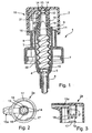
- a metering pump according to FIGS. 1 to 6 is exclusively made of pump components constructed in the form of plastic injection molded parts.
- the dosing pump 1 is made up of four plastic injection molded parts.
- a first plastic injection molded part is a housing 4, which with an integrally formed closure cap portion 7 for tight fitting the metering pump 1 to a non-illustrated media storage is provided in the form of a container.
- a pumping chamber of Dosing pump 1 is described by a bellows spring described in more detail below 3 formed, which is also designed as a plastic injection molded part.
- the bellows spring 3 is on its underside, i. at one to the side of the Medium storage inlet area, a plate or disc valve 5 assigned, which also represents a plastic injection molded part.
- a dosing in the present case in the form of a spray head 2, plugged, which is guided to the hub 4 on the housing.
- the housing 4 has a funnel-like receptacle into which the bellows spring 3 can be used from above.
- a connecting piece 6 is provided in the one not Specified riser or a riser hose can be inserted.
- the riser or the riser hose protrude into the interior of the media storage down to its bottom to the appropriate medium, in particular a liquid or a gel to suck.
- a shoulder-shaped gradation provided a valve seat for the plate valve 5 forms.
- the plate valve 5 is - on a central longitudinal axis of the Dosing pump 1 based - mounted axially movable, the mobility up through a corresponding annular shoulder portion 10th the bellows spring 3 is limited.
- the plate valve 5 forms an inlet valve for a pump chamber formed by the interior of the bellows spring 3.
- the Plate valve 5 opens as soon as a pressure within the bellows spring 3 arises relative to the pressure in the media storage. If the pressure within the pumping chamber is equal to or greater than the pressure in the media reservoir, the plate valve 5 seals an inlet opening in the inlet area 10 of the pumping chamber, i. at the lower end region of the bellows spring 3 or in the area of the housing-side valve seat, tight.
- the housing 4 has above the cap 7 forming Section a coaxial with the central longitudinal axis aligned, cylindrical Guide section 9, the inside in its upper edge region is provided with an annular stop shoulder.
- the stop shoulder serves to the Hubbewegige the bellows spring 3 after to limit above.
- the bellows spring 3 has a corresponding outwardly directed annular shoulder 11, the function of a guide piston within the cylindrical guide portion 9 of the Housing 4 takes over.
- the housing 4 Coaxially with the guide section 9, the housing 4 has a further outer, second sleeve ring 8, in the region of its upper End edge provided with an outwardly facing locking ring 16 is.
- On this locking ring 16 is an outer shell of the cup-shaped Dosing head 2 latched.
- the shell of the cup-shaped Dosing head 2 at its lower edge region on two opposite Pages each have a latch 17 on ( Figures 2 and 3).
- the Locking lugs of the dosing 2 correspond in shape and arrangement to the Latches 17 of the dosing head 2a according to FIGS. 2 and 3.
- the bellows spring 3 is in its lower portion with the inlet portion 10th provided, which frictionally with its conical outer periphery at a corresponding conical inner wall portion of the Housing 4 is supported.
- the bellows spring 3 is made of elastically yielding Material produced and in Fig. 6 schematically in its unloaded position shown.
- the bellows spring 3 is inserted into the housing 4 under prestress and clamped in its lower inlet portion 10 in the housing 4.
- the bellows spring 3 points to the lower inlet region 10 a helically shaped Belgmantel on, with different Wendelste Trenten is provided.
- the bellows spring 3 In a transitional area between the Guide piston area and the outlet area is the bellows spring 3 with an annular shoulder, which a gradation of the guide piston area with larger diameter to the exit area with a smaller diameter.
- the bellows spring 3 is made of a made of elastic plastic material.
- Fig. 5 are in this thicker area over the circumference of this cylindrical section distributed several grooves 20 provided, which are open at the top. These serve for recording of finger-shaped projections 18 of a guide piece 21 of the Dosing head 2a, wherein the guide piece 21 on the cylindrical Outlet of the bellows spring 3 can be plugged.
- the grooves 20 form together with the finger-shaped projections 18 a finger teeth and thus a rotational connection between dosing 2 and Bellows spring 3.
- the guide neck 21 and thus also the dosing 2 are on the outlet of the bellows spring 3 within certain limits axially held displaceable. For this purpose is between the guide piece 21st and the stepped shoulder of the bellows spring 3 an axial distance 19th intended. Also the lower front ends of the finger-shaped extensions 18 end at a distance above the bottom of the grooves 20.
- FIG. 1 represents an enlargement in scale 4: 1.
- the axial distance 19 is therefore only about 0.5mm.
- the Dosing head 2 is thus compared to the bellows spring 3 by about 0.5 mm lowered down without the bellows spring 3 itself lowered down and thereby being compressed.
- the hose valve portion 12 of the bellows spring 3 is provided with an annular Provide constriction, so that the cutting profile shown in Fig. 1 for the hose valve section 12.
- the hose valve section 12 has a circumferential upper end edge, which on a conical valve seat portion 13 on an inner side of a lid portion of the dosing head 2 rests tightly circumferentially.
- the conical valve seat section 13 is at its radially outer and thus according to FIG. 1 upper end with a plurality of venting ribs 14, as shown in FIG. 2 with two opposite venting ribs 14, provided. These vents 14 serve for a so-called priming the interior of Bellows spring, i. the pumping chamber to vent.
- the dosing 2 to the previously mentioned about 0.5mm down pressed.
- the upper annular edge of the hose valve section 12 slides along the inclined surfaces of the conical valve seat portion 13 upwards until it comes to rest on the venting ribs 14 and deformed by it. Due to this deformation in the area of Vent ribs is the upper end edge of the hose valve section 12 no longer circumferentially close to the conical valve seat portion 13, so that corresponding air can escape.
- the dosing head also has a basically known manner Spray nozzle 15, which is the application of the appropriate medium allows the interior of the bellows spring 3 to the outside.
- the housing 4 has below the cap portion 7 a Vent slot 22, which is a pressure compensation for the Container interior of the media storage causes.
- the vent slot 22 creates an opening between the media storage and the bellows spring. 3 comprehensive interior of the housing 4, so that over the cylindrical Guide section aeration of the container interior of the media storage allows, whereby a pressure equalization in the medium memory present at appropriate Ausbringvor réellen a medium is.
Landscapes
- Engineering & Computer Science (AREA)
- Mechanical Engineering (AREA)
- Manufacturing & Machinery (AREA)
- General Engineering & Computer Science (AREA)
- Reciprocating Pumps (AREA)
- Containers And Packaging Bodies Having A Special Means To Remove Contents (AREA)
- Injection Moulding Of Plastics Or The Like (AREA)
Claims (5)
- Pompe de dosage avec un ressort à soufflet en un matériau flexible et axialement souple le long d'un axe de pompage, dont la cavité est réalisée en tant que chambre de pompage, caractérisée en ce que le ressort à soufflet (3) auprès d'un domaine d'échappement, en direction d'une tête de dosage (2, 2a) est réalisé en tant que section de valve de gonflage (12), qui agit avec une section de siège de soupape (13) correspondante d'une tête de dosage (2, 2a) de la pompe de dosage.
- Pompe de dosage d'après la revendication 1, caractérisée en ce que la section de valve de gonflage (12) est munie d'une gorge annulaire à la manière d'un ressort à disque.
- Pompe de dosage d'après la revendication 1, caractérisée en ce que le ressort à soufflet (3) présente une section de guidage à glissement (11) logée dans un boítier de pompe (4) de manière déplaçable en direction de course.
- Pompe de dosage d'après la revendication 1, caractérisée en ce que la tête de dosage (2, 2a) présente une tubulure de guidage (21) qui recouvre axialement de l'extérieur le domaine d'échappement du ressort à soufflet (3) et qui repose de manière axialement mobile sur le domaine d'échappement du ressort à soufflet (3).
- Pompe de dosage d'après la revendication 2, caractérisée en ce que le ressort à soufflet (3) est maintenue à engagement par adhérence dans le boítier de pompe (4) dans un domaine d'admission (10).
Applications Claiming Priority (2)
| Application Number | Priority Date | Filing Date | Title |
|---|---|---|---|
| DE10229618A DE10229618A1 (de) | 2002-06-25 | 2002-06-25 | Dosierpumpe, Verfahren zu ihrer Herstellung und Vorrichtung zur Durchführung des Verfahrens |
| DE10229618 | 2002-06-25 |
Publications (3)
| Publication Number | Publication Date |
|---|---|
| EP1375010A2 EP1375010A2 (fr) | 2004-01-02 |
| EP1375010A3 EP1375010A3 (fr) | 2004-01-14 |
| EP1375010B1 true EP1375010B1 (fr) | 2005-02-09 |
Family
ID=29716746
Family Applications (2)
| Application Number | Title | Priority Date | Filing Date |
|---|---|---|---|
| EP03014135A Expired - Lifetime EP1375010B1 (fr) | 2002-06-25 | 2003-06-24 | Pompe à dosage, procédé de fabrication de cette pompe et appareil pour executer ce procédé |
| EP03014248A Expired - Lifetime EP1375011B1 (fr) | 2002-06-25 | 2003-06-25 | Appareil de dosage pour au moins un fluide |
Family Applications After (1)
| Application Number | Title | Priority Date | Filing Date |
|---|---|---|---|
| EP03014248A Expired - Lifetime EP1375011B1 (fr) | 2002-06-25 | 2003-06-25 | Appareil de dosage pour au moins un fluide |
Country Status (9)
| Country | Link |
|---|---|
| US (1) | US7223090B2 (fr) |
| EP (2) | EP1375010B1 (fr) |
| KR (1) | KR20040002661A (fr) |
| CN (1) | CN1493408A (fr) |
| AR (1) | AR040195A1 (fr) |
| AT (2) | ATE288791T1 (fr) |
| BR (1) | BR0302121A (fr) |
| DE (3) | DE10229618A1 (fr) |
| ES (2) | ES2237728T3 (fr) |
Families Citing this family (18)
| Publication number | Priority date | Publication date | Assignee | Title |
|---|---|---|---|---|
| JP4443991B2 (ja) * | 2004-04-23 | 2010-03-31 | 株式会社エヌ・ティ・ティ・ドコモ | 無線通信システム、受信装置及び受信方法 |
| ITBS20050013A1 (it) * | 2005-02-04 | 2006-08-05 | Guala Dispensing Spa | Dispositivo per l'erogazione di un fluido ed elemento pompante |
| US7432139B2 (en) * | 2005-06-29 | 2008-10-07 | Amberwave Systems Corp. | Methods for forming dielectrics and metal electrodes |
| US20070001231A1 (en) * | 2005-06-29 | 2007-01-04 | Amberwave Systems Corporation | Material systems for dielectrics and metal electrodes |
| US8238424B2 (en) * | 2007-02-09 | 2012-08-07 | Microsoft Corporation | Complexity-based adaptive preprocessing for multiple-pass video compression |
| TW201515714A (zh) | 2007-05-30 | 2015-05-01 | Glaxo Group Ltd | 流體分配器 |
| FR3053270B1 (fr) * | 2016-06-30 | 2019-04-05 | Bernard Renzo | Procede et outillage associe pour la fabrication par injection d'un manchon, et manchon en resultant |
| CN107932849B (zh) * | 2017-11-30 | 2019-07-09 | 重庆鑫际激光科技有限公司 | 用于计算机零部件的脱模模具 |
| EP3823763B1 (fr) | 2018-07-16 | 2023-09-06 | Softhale NV | Dispositif d'inhalation amélioré |
| JP7363022B2 (ja) * | 2018-10-29 | 2023-10-18 | 東洋製罐株式会社 | 弁体付ノズル部材、及び吐出キャップ、並びに射出成形型 |
| FR3090416B1 (fr) | 2018-12-24 | 2024-07-12 | Albea Services | Pompe pour flacon de produit cosmétique dotée de moyens de purge d’air |
| US10751740B2 (en) * | 2019-01-09 | 2020-08-25 | Tessy Plastics Corporation | Eco pump assembly |
| CN112173408B (zh) * | 2020-08-26 | 2024-10-29 | 宁波圣捷喷雾泵有限公司 | 一种泡沫泵 |
| CN112606319A (zh) * | 2020-12-02 | 2021-04-06 | 九江市哥瑞照明电器有限公司 | 一种注塑机自动抽料装置 |
| EP4341003A1 (fr) | 2021-05-20 | 2024-03-27 | Aptar Dortmund GmbH | Ressort en matière plastique et dispositif de distribution |
| DE102021122705B4 (de) | 2021-05-20 | 2025-06-18 | Aptar Dortmund Gmbh | Feder aus Kunststoff und Abgabevorrichtung |
| CN113636205A (zh) * | 2021-06-21 | 2021-11-12 | 广东尼特包装制品有限公司 | 一种全塑外置泡沫泵及其产生泡沫的方法 |
| USD1009082S1 (en) * | 2021-09-30 | 2023-12-26 | Viscotec Pumpen- U. Dosiertechnik Gmbh | Metering pump |
Family Cites Families (25)
| Publication number | Priority date | Publication date | Assignee | Title |
|---|---|---|---|---|
| DE2129752A1 (de) * | 1971-06-16 | 1972-12-28 | Karl Hehl | Spritzgiessform fuer eine Kunststoffe verarbeitende Spritzgiessmaschine zur Herstellung zweifarbiger Spritzlinge |
| CA1006666A (en) * | 1973-10-29 | 1977-03-15 | Ladislav Hujik | Mold filling insert for injection molding machine |
| FR2631564B1 (fr) | 1988-05-18 | 1990-08-17 | Step Soc Tech Pulverisation | Pompe-doseuse perfectionnee pour pulverisateurs |
| DE3817632A1 (de) * | 1988-05-25 | 1989-11-30 | Mega Prod Verpack Marketing | Insbesondere auf flaschen oder dergleichen aufsetzbare dosierpumpe |
| DE3839590A1 (de) | 1988-11-24 | 1990-05-31 | Pfeiffer Erich Gmbh & Co Kg | Ventil, insbesondere fuer manuelle austragvorrichtungen |
| DE4009661C1 (fr) * | 1990-03-26 | 1991-03-07 | Aisa Automation Industrielle S.A., Vouvry, Ch | |
| DE4110302A1 (de) * | 1991-03-28 | 1992-10-01 | Pfeiffer Erich Gmbh & Co Kg | Austragvorrichtung fuer medien |
| ATE164544T1 (de) | 1992-01-15 | 1998-04-15 | Johnson & Son Inc S C | Herstellung und verbindung einer stellerabdeckkappe mit einer einführdüse |
| IT1260302B (it) | 1993-03-12 | 1996-04-03 | Taplast Srl | Pompa dosatrice in plastica per l'erogazione di liquidi da contenitori |
| JP3586483B2 (ja) * | 1994-10-26 | 2004-11-10 | ファナック株式会社 | 射出成形機のエジェクト装置 |
| DE29508519U1 (de) | 1995-05-23 | 1996-09-19 | Frimec Fritz Meckenstock GmbH & Co, 42119 Wuppertal | Handhebelbetätigte Pumpe |
| DE19606702A1 (de) | 1996-02-22 | 1997-08-28 | Caideil M P Teoranta Tourmakea | Austragvorrichtung für Medien |
| DE19622124A1 (de) * | 1996-06-01 | 1997-12-04 | Alfred Von Schuckmann | Gerät zum Aufbringen von Flüssigkeiten |
| DE19624986C1 (de) * | 1996-06-22 | 1997-11-13 | Teves Gmbh Alfred | Verfahren zum Spritzgießen einer Teilefamilie |
| DE19627228A1 (de) | 1996-07-05 | 1998-01-08 | Pfeiffer Erich Gmbh & Co Kg | Austragvorrichtung für Medien |
| US5855932A (en) * | 1996-09-13 | 1999-01-05 | Electra Form, Inc. | Molded article retrieval apparatus |
| DE19713721C2 (de) * | 1997-04-03 | 2000-04-20 | Calmar Albert Gmbh | Spender |
| US6234412B1 (en) * | 1997-09-04 | 2001-05-22 | Alfred Von Schuckmann | Spray pump capable of being actuated by a hand lever |
| JP3390131B2 (ja) * | 1997-11-14 | 2003-03-24 | ジー・ピー・ダイキョー株式会社 | 中間体を組み込んだ合成樹脂製中空体の製造方法及びその装置並びに合成樹脂製中空体 |
| JP3368203B2 (ja) * | 1998-06-02 | 2003-01-20 | ジー・ピー・ダイキョー株式会社 | 合成樹脂製中空体の製造方法及びその装置 |
| DE19840723A1 (de) * | 1998-09-07 | 2000-03-09 | Pfeiffer Erich Gmbh & Co Kg | Spender für Medien |
| US6032834A (en) | 1998-10-22 | 2000-03-07 | Owens-Illinois Closure Inc. | Pump dispenser and method of making it |
| DE29917164U1 (de) * | 1999-09-29 | 2001-02-22 | G.B. Boucherie N.V., Izegem | Werkzeug zum Spritzgießen von Zahnbürstenkörpern aus mehreren Kunststoffkomponenten |
| GB0002198D0 (en) * | 2000-01-31 | 2000-03-22 | Swan Valley Mould Tools Ltd | Improvements in or relating to injection moulding apparatus |
| DE10017340A1 (de) * | 2000-04-07 | 2001-10-18 | Rosenthal Karl Heinz | Pumpe |
-
2002
- 2002-06-25 DE DE10229618A patent/DE10229618A1/de not_active Withdrawn
-
2003
- 2003-06-11 AR ARP030102086A patent/AR040195A1/es active IP Right Grant
- 2003-06-24 AT AT03014135T patent/ATE288791T1/de not_active IP Right Cessation
- 2003-06-24 US US10/603,059 patent/US7223090B2/en not_active Expired - Fee Related
- 2003-06-24 BR BR0302121-1A patent/BR0302121A/pt not_active IP Right Cessation
- 2003-06-24 KR KR1020030041005A patent/KR20040002661A/ko not_active Withdrawn
- 2003-06-24 DE DE50300302T patent/DE50300302D1/de not_active Expired - Lifetime
- 2003-06-24 EP EP03014135A patent/EP1375010B1/fr not_active Expired - Lifetime
- 2003-06-24 ES ES03014135T patent/ES2237728T3/es not_active Expired - Lifetime
- 2003-06-25 ES ES03014248T patent/ES2237729T3/es not_active Expired - Lifetime
- 2003-06-25 CN CNA031487602A patent/CN1493408A/zh active Pending
- 2003-06-25 DE DE50300303T patent/DE50300303D1/de not_active Expired - Lifetime
- 2003-06-25 EP EP03014248A patent/EP1375011B1/fr not_active Expired - Lifetime
- 2003-06-25 AT AT03014248T patent/ATE288792T1/de not_active IP Right Cessation
Also Published As
| Publication number | Publication date |
|---|---|
| CN1493408A (zh) | 2004-05-05 |
| EP1375010A3 (fr) | 2004-01-14 |
| ATE288791T1 (de) | 2005-02-15 |
| AR040195A1 (es) | 2005-03-16 |
| ES2237729T3 (es) | 2005-08-01 |
| EP1375011B1 (fr) | 2005-02-09 |
| KR20040002661A (ko) | 2004-01-07 |
| ATE288792T1 (de) | 2005-02-15 |
| DE10229618A1 (de) | 2004-01-29 |
| EP1375010A2 (fr) | 2004-01-02 |
| EP1375011A1 (fr) | 2004-01-02 |
| US7223090B2 (en) | 2007-05-29 |
| DE50300302D1 (de) | 2005-03-17 |
| US20040026458A1 (en) | 2004-02-12 |
| ES2237728T3 (es) | 2005-08-01 |
| BR0302121A (pt) | 2004-08-17 |
| DE50300303D1 (de) | 2005-03-17 |
Similar Documents
| Publication | Publication Date | Title |
|---|---|---|
| EP0088236B2 (fr) | Distributeur des produits liquides ou pâteux | |
| EP0312722B1 (fr) | Pompe de dosage et d'atomisation pour matières liquides ou visqueuses | |
| DE69300399T2 (de) | Vordruckpumpe. | |
| EP0112351B1 (fr) | Distribution de produits pateux | |
| EP0923993B1 (fr) | Distributeur de fluide | |
| EP0199143B1 (fr) | Pompe à piston coulissant pour délivrer des substances fluides | |
| EP1842798B1 (fr) | Soupape de dosage et dispositif destiné à la livraison d'un liquide cosmétique de préférence | |
| DE10335842B4 (de) | Abgabepackung | |
| WO2003026803A1 (fr) | Dispositif de dosage muni d'un systeme de pompage | |
| EP0217013B1 (fr) | Ressort à gaz réglable en longueur | |
| EP1375010A2 (fr) | Pompe à dosage, procédé de fabrication de cette pompe et appareil pour executer ce procédé | |
| WO2003026805A1 (fr) | Dispositif de dosage pourvu d'un reservoir de substances et dispositif de pompage correspondant | |
| EP3493917B1 (fr) | Pompe de pulvérisation à doigt | |
| EP0791399B1 (fr) | Dispositif de décharge d'un fluide | |
| EP0791398B1 (fr) | Dispositif de décharge d'un fluide | |
| EP1295645B1 (fr) | Dispositif de dosage muni d'une pompe | |
| EP0443192B1 (fr) | Tête de distribution pour fluides | |
| EP0887112A2 (fr) | Distributeur de fluides | |
| DE102010063587B4 (de) | Austragvorrichtung für eine Flüssigkeit | |
| WO2019072943A1 (fr) | Distributeur de matières liquides ou pâteuses | |
| EP2624964B1 (fr) | Distributeur à pompe avec valves flexibles | |
| WO1985000984A1 (fr) | Valve de retenue pour application medicale, notamment pour catheter ballon | |
| EP0505900A1 (fr) | Distributeur de fluides | |
| DE102005012506A1 (de) | Abgabevorrichtung | |
| DE19715709B4 (de) | Flüssigkeitsdispenser, Förder-und Dosierzylinder, Förder-und Dosiervorrichtung und Verfahren zur Herstellung eines Flüssigkeitsdispensers |
Legal Events
| Date | Code | Title | Description |
|---|---|---|---|
| PUAI | Public reference made under article 153(3) epc to a published international application that has entered the european phase |
Free format text: ORIGINAL CODE: 0009012 |
|
| PUAL | Search report despatched |
Free format text: ORIGINAL CODE: 0009013 |
|
| AK | Designated contracting states |
Kind code of ref document: A2 Designated state(s): AT BE BG CH CY CZ DE DK EE ES FI FR GB GR HU IE IT LI LU MC NL PT RO SE SI SK TR |
|
| AX | Request for extension of the european patent |
Extension state: AL LT LV MK |
|
| AK | Designated contracting states |
Kind code of ref document: A3 Designated state(s): AT BE BG CH CY CZ DE DK EE ES FI FR GB GR HU IE IT LI LU MC NL PT RO SE SI SK TR |
|
| AX | Request for extension of the european patent |
Extension state: AL LT LV MK |
|
| 17P | Request for examination filed |
Effective date: 20040204 |
|
| 17Q | First examination report despatched |
Effective date: 20040308 |
|
| GRAP | Despatch of communication of intention to grant a patent |
Free format text: ORIGINAL CODE: EPIDOSNIGR1 |
|
| AKX | Designation fees paid |
Designated state(s): AT BE BG CH CY CZ DE DK EE ES FI FR GB GR HU IE IT LI LU MC NL PT RO SE SI SK TR |
|
| GRAS | Grant fee paid |
Free format text: ORIGINAL CODE: EPIDOSNIGR3 |
|
| GRAA | (expected) grant |
Free format text: ORIGINAL CODE: 0009210 |
|
| AK | Designated contracting states |
Kind code of ref document: B1 Designated state(s): AT BE BG CH CY CZ DE DK EE ES FI FR GB GR HU IE IT LI LU MC NL PT RO SE SI SK TR |
|
| PG25 | Lapsed in a contracting state [announced via postgrant information from national office to epo] |
Ref country code: SI Free format text: LAPSE BECAUSE OF FAILURE TO SUBMIT A TRANSLATION OF THE DESCRIPTION OR TO PAY THE FEE WITHIN THE PRESCRIBED TIME-LIMIT Effective date: 20050209 Ref country code: SK Free format text: LAPSE BECAUSE OF FAILURE TO SUBMIT A TRANSLATION OF THE DESCRIPTION OR TO PAY THE FEE WITHIN THE PRESCRIBED TIME-LIMIT Effective date: 20050209 Ref country code: EE Free format text: LAPSE BECAUSE OF FAILURE TO SUBMIT A TRANSLATION OF THE DESCRIPTION OR TO PAY THE FEE WITHIN THE PRESCRIBED TIME-LIMIT Effective date: 20050209 Ref country code: TR Free format text: LAPSE BECAUSE OF FAILURE TO SUBMIT A TRANSLATION OF THE DESCRIPTION OR TO PAY THE FEE WITHIN THE PRESCRIBED TIME-LIMIT Effective date: 20050209 Ref country code: IE Free format text: LAPSE BECAUSE OF FAILURE TO SUBMIT A TRANSLATION OF THE DESCRIPTION OR TO PAY THE FEE WITHIN THE PRESCRIBED TIME-LIMIT Effective date: 20050209 Ref country code: BG Free format text: LAPSE BECAUSE OF FAILURE TO SUBMIT A TRANSLATION OF THE DESCRIPTION OR TO PAY THE FEE WITHIN THE PRESCRIBED TIME-LIMIT Effective date: 20050209 Ref country code: FI Free format text: LAPSE BECAUSE OF FAILURE TO SUBMIT A TRANSLATION OF THE DESCRIPTION OR TO PAY THE FEE WITHIN THE PRESCRIBED TIME-LIMIT Effective date: 20050209 Ref country code: RO Free format text: LAPSE BECAUSE OF FAILURE TO SUBMIT A TRANSLATION OF THE DESCRIPTION OR TO PAY THE FEE WITHIN THE PRESCRIBED TIME-LIMIT Effective date: 20050209 Ref country code: NL Free format text: LAPSE BECAUSE OF FAILURE TO SUBMIT A TRANSLATION OF THE DESCRIPTION OR TO PAY THE FEE WITHIN THE PRESCRIBED TIME-LIMIT Effective date: 20050209 Ref country code: CZ Free format text: LAPSE BECAUSE OF FAILURE TO SUBMIT A TRANSLATION OF THE DESCRIPTION OR TO PAY THE FEE WITHIN THE PRESCRIBED TIME-LIMIT Effective date: 20050209 |
|
| REG | Reference to a national code |
Ref country code: GB Ref legal event code: FG4D Free format text: NOT ENGLISH |
|
| REG | Reference to a national code |
Ref country code: CH Ref legal event code: EP |
|
| REG | Reference to a national code |
Ref country code: IE Ref legal event code: FG4D Free format text: GERMAN |
|
| REF | Corresponds to: |
Ref document number: 50300302 Country of ref document: DE Date of ref document: 20050317 Kind code of ref document: P |
|
| GBT | Gb: translation of ep patent filed (gb section 77(6)(a)/1977) |
Effective date: 20050314 |
|
| REG | Reference to a national code |
Ref country code: CH Ref legal event code: NV Representative=s name: ZIMMERLI, WAGNER & PARTNER AG |
|
| PG25 | Lapsed in a contracting state [announced via postgrant information from national office to epo] |
Ref country code: DK Free format text: LAPSE BECAUSE OF FAILURE TO SUBMIT A TRANSLATION OF THE DESCRIPTION OR TO PAY THE FEE WITHIN THE PRESCRIBED TIME-LIMIT Effective date: 20050509 Ref country code: GR Free format text: LAPSE BECAUSE OF FAILURE TO SUBMIT A TRANSLATION OF THE DESCRIPTION OR TO PAY THE FEE WITHIN THE PRESCRIBED TIME-LIMIT Effective date: 20050509 Ref country code: SE Free format text: LAPSE BECAUSE OF FAILURE TO SUBMIT A TRANSLATION OF THE DESCRIPTION OR TO PAY THE FEE WITHIN THE PRESCRIBED TIME-LIMIT Effective date: 20050509 |
|
| PG25 | Lapsed in a contracting state [announced via postgrant information from national office to epo] |
Ref country code: HU Free format text: LAPSE BECAUSE OF FAILURE TO SUBMIT A TRANSLATION OF THE DESCRIPTION OR TO PAY THE FEE WITHIN THE PRESCRIBED TIME-LIMIT Effective date: 20050510 |
|
| PG25 | Lapsed in a contracting state [announced via postgrant information from national office to epo] |
Ref country code: AT Free format text: LAPSE BECAUSE OF NON-PAYMENT OF DUE FEES Effective date: 20050624 Ref country code: CY Free format text: LAPSE BECAUSE OF FAILURE TO SUBMIT A TRANSLATION OF THE DESCRIPTION OR TO PAY THE FEE WITHIN THE PRESCRIBED TIME-LIMIT Effective date: 20050624 Ref country code: LU Free format text: LAPSE BECAUSE OF NON-PAYMENT OF DUE FEES Effective date: 20050624 |
|
| PG25 | Lapsed in a contracting state [announced via postgrant information from national office to epo] |
Ref country code: MC Free format text: LAPSE BECAUSE OF NON-PAYMENT OF DUE FEES Effective date: 20050630 Ref country code: BE Free format text: LAPSE BECAUSE OF NON-PAYMENT OF DUE FEES Effective date: 20050630 |
|
| NLV1 | Nl: lapsed or annulled due to failure to fulfill the requirements of art. 29p and 29m of the patents act | ||
| REG | Reference to a national code |
Ref country code: ES Ref legal event code: FG2A Ref document number: 2237728 Country of ref document: ES Kind code of ref document: T3 |
|
| REG | Reference to a national code |
Ref country code: IE Ref legal event code: FD4D |
|
| PLBE | No opposition filed within time limit |
Free format text: ORIGINAL CODE: 0009261 |
|
| STAA | Information on the status of an ep patent application or granted ep patent |
Free format text: STATUS: NO OPPOSITION FILED WITHIN TIME LIMIT |
|
| 26N | No opposition filed |
Effective date: 20051110 |
|
| ET | Fr: translation filed | ||
| BERE | Be: lapsed |
Owner name: ING. ERICH PFEIFFER G.M.B.H. Effective date: 20050630 |
|
| PG25 | Lapsed in a contracting state [announced via postgrant information from national office to epo] |
Ref country code: PT Free format text: LAPSE BECAUSE OF NON-PAYMENT OF DUE FEES Effective date: 20050709 |
|
| REG | Reference to a national code |
Ref country code: CH Ref legal event code: PFA Owner name: ING. ERICH PFEIFFER GMBH Free format text: ING. ERICH PFEIFFER GMBH#OESCHLESTRASSE 124-126#78315 RADOLFZELL (DE) -TRANSFER TO- ING. ERICH PFEIFFER GMBH#OESCHLESTRASSE 124-126#78315 RADOLFZELL (DE) |
|
| PGFP | Annual fee paid to national office [announced via postgrant information from national office to epo] |
Ref country code: ES Payment date: 20100628 Year of fee payment: 8 |
|
| PGFP | Annual fee paid to national office [announced via postgrant information from national office to epo] |
Ref country code: CH Payment date: 20120622 Year of fee payment: 10 |
|
| PGFP | Annual fee paid to national office [announced via postgrant information from national office to epo] |
Ref country code: IT Payment date: 20120626 Year of fee payment: 10 |
|
| REG | Reference to a national code |
Ref country code: ES Ref legal event code: FD2A Effective date: 20121116 |
|
| REG | Reference to a national code |
Ref country code: DE Ref legal event code: R081 Ref document number: 50300302 Country of ref document: DE Owner name: APTAR RADOLFZELL GMBH, DE Free format text: FORMER OWNER: ING. ERICH PFEIFFER GMBH, 78315 RADOLFZELL, DE Effective date: 20121025 Ref country code: DE Ref legal event code: R082 Ref document number: 50300302 Country of ref document: DE Representative=s name: PATENTANWAELTE RUFF, WILHELM, BEIER, DAUSTER &, DE Effective date: 20121025 Ref country code: DE Ref legal event code: R082 Ref document number: 50300302 Country of ref document: DE Representative=s name: PATENTANWALTSKANZLEI CARTAGENA PARTNERSCHAFTSG, DE Effective date: 20121025 |
|
| PG25 | Lapsed in a contracting state [announced via postgrant information from national office to epo] |
Ref country code: ES Free format text: LAPSE BECAUSE OF NON-PAYMENT OF DUE FEES Effective date: 20110625 |
|
| REG | Reference to a national code |
Ref country code: CH Ref legal event code: PL |
|
| PG25 | Lapsed in a contracting state [announced via postgrant information from national office to epo] |
Ref country code: CH Free format text: LAPSE BECAUSE OF NON-PAYMENT OF DUE FEES Effective date: 20130630 Ref country code: LI Free format text: LAPSE BECAUSE OF NON-PAYMENT OF DUE FEES Effective date: 20130630 |
|
| PG25 | Lapsed in a contracting state [announced via postgrant information from national office to epo] |
Ref country code: IT Free format text: LAPSE BECAUSE OF NON-PAYMENT OF DUE FEES Effective date: 20130624 |
|
| PGFP | Annual fee paid to national office [announced via postgrant information from national office to epo] |
Ref country code: GB Payment date: 20140620 Year of fee payment: 12 |
|
| REG | Reference to a national code |
Ref country code: DE Ref legal event code: R082 Ref document number: 50300302 Country of ref document: DE Representative=s name: PATENTANWALTSKANZLEI CARTAGENA PARTNERSCHAFTSG, DE |
|
| GBPC | Gb: european patent ceased through non-payment of renewal fee |
Effective date: 20150624 |
|
| PG25 | Lapsed in a contracting state [announced via postgrant information from national office to epo] |
Ref country code: GB Free format text: LAPSE BECAUSE OF NON-PAYMENT OF DUE FEES Effective date: 20150624 |
|
| REG | Reference to a national code |
Ref country code: FR Ref legal event code: PLFP Year of fee payment: 14 |
|
| REG | Reference to a national code |
Ref country code: FR Ref legal event code: PLFP Year of fee payment: 15 |
|
| PGFP | Annual fee paid to national office [announced via postgrant information from national office to epo] |
Ref country code: DE Payment date: 20170622 Year of fee payment: 15 Ref country code: FR Payment date: 20170621 Year of fee payment: 15 |
|
| REG | Reference to a national code |
Ref country code: DE Ref legal event code: R119 Ref document number: 50300302 Country of ref document: DE |
|
| PG25 | Lapsed in a contracting state [announced via postgrant information from national office to epo] |
Ref country code: DE Free format text: LAPSE BECAUSE OF NON-PAYMENT OF DUE FEES Effective date: 20190101 Ref country code: FR Free format text: LAPSE BECAUSE OF NON-PAYMENT OF DUE FEES Effective date: 20180630 |