EP1375201B1 - Adaptateur pour attacher des chaînes à neige sur des roues de véhicule - Google Patents
Adaptateur pour attacher des chaînes à neige sur des roues de véhicule Download PDFInfo
- Publication number
- EP1375201B1 EP1375201B1 EP02425425A EP02425425A EP1375201B1 EP 1375201 B1 EP1375201 B1 EP 1375201B1 EP 02425425 A EP02425425 A EP 02425425A EP 02425425 A EP02425425 A EP 02425425A EP 1375201 B1 EP1375201 B1 EP 1375201B1
- Authority
- EP
- European Patent Office
- Prior art keywords
- adapter device
- wheel
- plate
- head
- snow chains
- Prior art date
- Legal status (The legal status is an assumption and is not a legal conclusion. Google has not performed a legal analysis and makes no representation as to the accuracy of the status listed.)
- Expired - Lifetime
Links
- 238000009434 installation Methods 0.000 claims abstract description 13
- 230000014759 maintenance of location Effects 0.000 claims abstract description 6
- 239000002184 metal Substances 0.000 description 2
- 238000004026 adhesive bonding Methods 0.000 description 1
- 230000001419 dependent effect Effects 0.000 description 1
- 238000012986 modification Methods 0.000 description 1
- 230000004048 modification Effects 0.000 description 1
- 230000000284 resting effect Effects 0.000 description 1
- 230000000717 retained effect Effects 0.000 description 1
- 238000003466 welding Methods 0.000 description 1
Images


Classifications
-
- B—PERFORMING OPERATIONS; TRANSPORTING
- B60—VEHICLES IN GENERAL
- B60C—VEHICLE TYRES; TYRE INFLATION; TYRE CHANGING; CONNECTING VALVES TO INFLATABLE ELASTIC BODIES IN GENERAL; DEVICES OR ARRANGEMENTS RELATED TO TYRES
- B60C27/00—Non-skid devices temporarily attachable to resilient tyres or resiliently-tyred wheels
- B60C27/06—Non-skid devices temporarily attachable to resilient tyres or resiliently-tyred wheels extending over the complete circumference of the tread, e.g. made of chains or cables
-
- B—PERFORMING OPERATIONS; TRANSPORTING
- B60—VEHICLES IN GENERAL
- B60C—VEHICLE TYRES; TYRE INFLATION; TYRE CHANGING; CONNECTING VALVES TO INFLATABLE ELASTIC BODIES IN GENERAL; DEVICES OR ARRANGEMENTS RELATED TO TYRES
- B60C27/00—Non-skid devices temporarily attachable to resilient tyres or resiliently-tyred wheels
-
- B—PERFORMING OPERATIONS; TRANSPORTING
- B60—VEHICLES IN GENERAL
- B60C—VEHICLE TYRES; TYRE INFLATION; TYRE CHANGING; CONNECTING VALVES TO INFLATABLE ELASTIC BODIES IN GENERAL; DEVICES OR ARRANGEMENTS RELATED TO TYRES
- B60C27/00—Non-skid devices temporarily attachable to resilient tyres or resiliently-tyred wheels
- B60C27/06—Non-skid devices temporarily attachable to resilient tyres or resiliently-tyred wheels extending over the complete circumference of the tread, e.g. made of chains or cables
- B60C27/061—Non-skid devices temporarily attachable to resilient tyres or resiliently-tyred wheels extending over the complete circumference of the tread, e.g. made of chains or cables provided with radial arms for supporting the ground engaging parts on the tread
-
- B—PERFORMING OPERATIONS; TRANSPORTING
- B60—VEHICLES IN GENERAL
- B60C—VEHICLE TYRES; TYRE INFLATION; TYRE CHANGING; CONNECTING VALVES TO INFLATABLE ELASTIC BODIES IN GENERAL; DEVICES OR ARRANGEMENTS RELATED TO TYRES
- B60C27/00—Non-skid devices temporarily attachable to resilient tyres or resiliently-tyred wheels
- B60C27/06—Non-skid devices temporarily attachable to resilient tyres or resiliently-tyred wheels extending over the complete circumference of the tread, e.g. made of chains or cables
- B60C27/062—Non-skid devices temporarily attachable to resilient tyres or resiliently-tyred wheels extending over the complete circumference of the tread, e.g. made of chains or cables provided with fastening means
- B60C27/063—Non-skid devices temporarily attachable to resilient tyres or resiliently-tyred wheels extending over the complete circumference of the tread, e.g. made of chains or cables provided with fastening means acting on the wheel, e.g. on the rim or wheel bolts
-
- Y—GENERAL TAGGING OF NEW TECHNOLOGICAL DEVELOPMENTS; GENERAL TAGGING OF CROSS-SECTIONAL TECHNOLOGIES SPANNING OVER SEVERAL SECTIONS OF THE IPC; TECHNICAL SUBJECTS COVERED BY FORMER USPC CROSS-REFERENCE ART COLLECTIONS [XRACs] AND DIGESTS
- Y10—TECHNICAL SUBJECTS COVERED BY FORMER USPC
- Y10S—TECHNICAL SUBJECTS COVERED BY FORMER USPC CROSS-REFERENCE ART COLLECTIONS [XRACs] AND DIGESTS
- Y10S411/00—Expanded, threaded, driven, headed, tool-deformed, or locked-threaded fastener
- Y10S411/91—Antitamper means
Definitions
- the present invention refers to an adapter for fastening snow chains to vehicle wheels.
- a type of snow chain is currently known on the market comprising various sections of chain closed in a loop and disposed on the tread of the tyre of the vehicle wheel. Said sections of chain are connected to arms or spokes disposed radially on the outside of the wheel and ending in a box or disc-shaped plate designed to be disposed substantially coaxially to the wheel hub. Said disc-shaped plate is fixed to the wheel by means of an adapter device which grips the head of at least one of the wheel mounting bolts.
- Adapter devices are known on the market in the form of a cylindrical sleeve provided with an operating ring nut, rotation whereof operates the teeth for tightening to the head of the wheel bolt.
- Said operating ring nut is disposed on the outside of the sleeve to be able to be operated in rotation by the user, possibly with the aid of a special key, such as for example the hexagonal key used for fitting/removing the wheels of the vehicle.
- Said adapter device can have a transverse hole to receive a bar connected to the disc-shaped plate of the arms of the snow chains, or other fastening means, such as a transverse lever with an end hole, which is disposed more or less in the centre of the rim.
- adapter device which comprise a disc-shaped plate provided with mechanical clamping means which grip all the bolts of a wheel.
- the object of the present invention is to eliminate the drawbacks of the prior art by providing an adapter device for fastening snow chains to vehicle wheels that is able to simplify the operation for installation thereof and reduce the time required for said installation operation.
- Another object of the present invention is to provide such an adapter device that is versatile and able to adapt to various types of wheels and snow chains.
- Another object of the present invention is to provide such an adapter device that is extremely reliable, safe and able to ensure a good grip of the snow chain to the wheel of the vehicle.
- Another object of the present invention is to provide such an adapter device that is inexpensive and simple to make.
- an adapter device For fastening snow chains to the wheels of vehicles, an adapter device is used that is fixed to the head of a bolt of a vehicle wheel.
- the adapter device comprises a body whereon connecting means able to be connected to connection and installation elements of snow chains are provided.
- the main characteristic of the invention is represented by the fact that said adapter device comprises magnetic means connected to the body of the adapter device and able to grip the head of at least one wheel bolt. In this manner, the body of the adapter device is firmly constrained to the wheel by magnetic retention between the magnetic means and the head of the wheel bolt, which is metal.
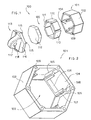
- the adapter device 100 comprises a body 101 having substantially a hexagonal nut shape.
- the body 101 is hollow on the inside and is open at the front and at the rear so as to give rise to a through hole 103 defined by a side wall 102 having a substantially hexagonal profile seen in cross section.
- Each rectangular seat 104 is defined in the inside surface of the side wall 102 of the body, one for each face of the side wall 102.
- Each rectangular seat 104 is defined by a substantially U-shaped frame formed by two guiding side bulkheads 105 and one front abutment bulkhead 106.
- the side bulkheads 105 have inwardly protruding ribs 107.
- the ribs 107 have a substantially Y-shaped cross section and are cut transversally, so as to give rise to a rear abutment surface 108.
- Holes 109 for pins with a longitudinal axis are provided in the rear edge of the side wall 102.
- the holes for pins 109 are preferably disposed in proximity to the six vertices of the rear edge of the side wall 102.
- the adapter device 100 comprises a group of magnets indicated as a whole with reference numeral 120.
- the group of magnets 120 comprises six side magnets 110 and one rear magnet 112.
- Each side magnet 110 is shaped like a rectangular plate suitable to be housed inside a respective seat 104 of the body 101. In this manner, each side magnet plate 110 is guided by the side bulkheads 105 and the ribs 107 until the front edge of the magnetic plate 110 abuts against the front abutment bulkhead 106.
- the side magnetic plates 110 are of substantially the same length as the ribs 107. In this manner, when the side magnetic plates 110 are inside the respective seats 104, the extreme rear edge 111 of each side magnetic plate 110 is at the same level as the rear abutment surface 108 of the ribs 107.
- the rear magnet 112 is shaped like a substantially hexagonal plate having such dimensions as to be able to be inserted into the body 101. In this manner the rear magnetic plate 112 abuts against the rear edges 111 of the side magnetic plates and against the abutment surfaces 108 of the ribs 107 of the body.
- the side magnetic plates 110 are able to come into contact with the respective side faces of the head of a wheel mounting bolt, such as bolt with a hexagonal head.
- the rear magnetic plate 112 is able to come into contact with the front face of the head of a wheel mounting bolt.
- the adapter device 100 comprises a closing cover 113 suitable to be applied to the rear part of the body 101 to close the magnet assembly 120 inside the body 101.
- the closing cover 113 comprises a rear closing plate 114 having a substantially hexagonal shape with a perimeter substantially similar to that of the rim of the side wall 102 of the body.
- a plurality of pins 115 able to press-engage in the holes 109 provided in the rear edge of the side wall 102 of the body are provided in the front surface of the closing plate 114.
- the closing plate 114 can be fastened to the body 102 by means of other fastening means, such as welding, gluing and the like.
- the closing plate 114 can be made in a single body with the body 101 and in this case the group of magnets 120 is fixed by means of suitable fastening means inside the body 101.
- the magnet assembly 120 can be incorporated into the body 101 and/or into the rear closing plate 114.
- the magnet assembly 120 can comprise only one magnetic element or a different number of magnetic elements made in different shapes from those shown in the figures.
- the essential condition is represented by the fact that the magnet assembly 120 disposed inside the body 101 gives rise to a hole 116 (Fig. 3) able to receive the head of a fastening bolt, such as, for example, a bolt with a hexagonal head, generally used for mounting a wheel of a vehicle.
- a flange 117 which protrudes rearward and has a transverse through hole 118 having an axis substantially parallel to the plane of the closing plate 114 is provided on the rear surface of the closing plate 114.
- the adapter device 100 has been designed for fastening snow chains connected to radial arms ending in a disc-shaped plate provided with a fastening bar. Consequently, the adapter device 100 must be mounted in such a manner that the axis of the hole 118 of the adapter device is directed towards the axis passing through the centre of the wheel rim. In this manner the hole 118 can receive the fastening bar connected to the disc-shaped plate of the radial arms of the snow chains.
- the magnet assembly 120 acts through a magnetic hold on the head 130 of the wheel bolt, which is metal, ensuring a firm grip of the adapter device 100. After various experimental tests, the applicant has ascertained that the magnetic retention exerted by the magnets 120 is sufficient to ensure the hold of the adapter device 100 on the head of the bolt 130, even when the vehicle is travelling.
- Removal of the adapter device 100 also is extremely simple, in fact it is sufficient for the user to exert a manual pull thereon to overcome the magnetic retention force.
- Figures 5 and 6 show a second embodiment of the adapter device designated as a whole with reference numeral 200.
- the only difference between the adapter device 100 and the adapter device 200 is represented by the fact that on the closing plate 144 of the adapter device 200, instead of the flange 117 being provided, a pin 217 is provided which protrudes forward therefrom in an axial direction.
- the pin 217 has an annular groove 218, disposed in proximity to its free end and the free end 219 of the pin 217 is substantially pointed.
- the pin 217 is able to snap or press engage in a pivot hole formed in a special lever connected to the disc-shaped plate of the radial arms connected to the snow chain.
- Figures 7 and 8 show a third embodiment of an adapter advice designated as a whole with reference numeral 300.
- a cylindrical tang 317 that protrudes rearward therefrom in an axial direction is provided.
- the cylindrical tang 317 has an axial hole 318 for a pin.
- An engaging lever 330 has at one end a first through hole 331 and at the other end a second through hole 332.
- the first through hole 331 of the lever 330 is able to receive the cylindrical tang 317 of the closing plate 114, so that the axial hole 318 of the cylindrical tang 317 can be press or snap engaged by a pin 333 mounted on a button 334.
- the closing plate 114 is constrained to the lever 330 and the lever 330 can turn relatively with respect to the closing plate, around the axis of the tang 317 of the closing plate.
- FIGS 10-13 show a fourth embodiment of an adapter device designated as a whole with reference numeral 400.
- the adapter device 400 comprises a front plate 401 and a rear plate 402, both substantially disc-shaped.
- Each through hole 404 disposed in positions corresponding to the positions of the heads of the wheel mounting bolts of a vehicle are provided in the front plate 401.
- Respective housings able to receive respective magnets 403 shaped like a disc-shaped plate are formed in the rear surface of the front plate 401 around each hole 404.
- a cylindrical tang 430 having an inside diameter such as to be able to house the head of a wheel mounting nut of a vehicle is provided around each hole 104 in the front surface of each front plate 401.
- the rear plate 402 has pins 405 able to engage in respective holes for pins 406 provided in the front plate 401. In this manner, when the two plates 401, 402 are assembled, the magnets 403 remain fixed in position in their seats.
- a tang In the rear plate, in a central position, a tang is formed with a through hole 407 wherein a tie-rod 408 blocked at one end by a ring 409 passes.
- the tie-rod 408 serves to fasten the adapter device 400 to the snow chains.
- an operating lever 411 is hinged by means of a transverse pin 412 to two supporting flanges 410 disposed in the rear surface of the rear plate 402. In this manner the operating lever 411 can turn around the axis of the pin 412.
- the operating lever 411 has a rounded end surface 413 which acts as a cam. Between the flanges 410, a through hole is formed in the rear plate 402 which receives an operating pin 414 the rounded head 415 whereof cooperates with the cam-shaped end 413 of the operating lever 411.
- one of the magnets 403 has, in a central position, a through hole 416 through which the operating pin 414 can pass.
- the operating lever 411 when the operating lever 411 is in the resting position, that is to say, substantially parallel to the surface of the rear plate 402, the end of the operating pin 414 is retracted within the hole 416 of the magnet 403.
- the operating lever 411 when the operating lever 411 is in the operating position, that is to say substantially at right angles to the surface of the rear plate 402, the end of the operating pin 414 is extracted from the hole 416 of the magnet 403.
- the user applies said adapter device to the wheel bolts, so that the heads of the bolts are housed in the seats formed in the tangs 430 and are retained by the magnets 403.
- the user When the adapter device 400 must be removed, the user operates the operating lever 411, bringing it into the working position, substantially at right angles to the surface of the rear plate 402. In this manner, the cam surface 413 of the operating lever 411 acts on the head of the pin 414. Consequently, the end of the pin 414 protrudes from the hole 416 of the magnet and pushes the head of the wheel bolt, causing detachment of the relative magnet 403 from the wheel bolt. In this manner the user, by exerting a minimum pulling force on the adapter device 400, succeeds in detaching it from the wheel bolts.
Landscapes
- Engineering & Computer Science (AREA)
- Mechanical Engineering (AREA)
- Tires In General (AREA)
- Handcart (AREA)
Claims (15)
- Adaptateur (100 ;200 ;300 ;400) pour attacher des chaînes à neige sur des roues de véhicule, ledit adaptateur étant apte à être appliqué sur la tête (130) d' au moins un boulon de roue et comprenant un corps sur lequel sont prévus des moyens de raccord appropriés afin d'être raccordés aux éléments d'installation et de raccord des chaînes à neige, caractérisé en ce que ledit adaptateur comprend des moyens magnétiques (120 ;403) aptes à mettre en prise ladite tête (130) d'au moins un boulon de roue, de manière à contraindre fermement le corps de l'adaptateur sur la roue, au moyen d'une rétention magnétique.
- Adaptateur (100 ;200 ;300) selon la revendication 1, caractérisé en ce que ledit adaptateur comprend un corps (101) de forme essentiellement semblable à un écrou hexagonal définissant un siège (116) possédant une section transversale essentiellement hexagonale afin de recevoir la tête (130) d'un boulon de montage de roue.
- Adaptateur (100 ;200 ;300) selon la revendication 2, caractérisé en ce que, à l'intérieur dudit corps (101) de l'adaptateur, des sièges latéraux (104) sont formés de manière à recevoir des plaques magnétiques (110) essentiellement rectangulaires respectives, destinées à venir en contact avec des faces latérales (130) respectives de la tête (130) d'un boulon de montage de roue.
- Adaptateur (100 ;200 ;300) selon la revendication 3, caractérisé en ce que chaque siège latéral (104) est défini par un cadre essentiellement en forme de U comprenant deux tabliers (105) de guidage latéraux et un tablier de butée (106) frontal.
- Adaptateur (100 ;200 ;300) selon la revendication 4, caractérisé en ce que sur chaque tablier latéral (105), une nervure (107) est formée, possédant une section transversale essentiellement en forme de Y et définissant une surface de butée arrière (108).
- Adaptateur (100 ;200 ;300) selon la revendication 5, caractérisé en ce que il comprend une plaque magnétique arrière (112), de forme essentiellement hexagonale, disposée sur le bord arrière desdites plaques magnétiques latérales (110) et sur ladite surface de butée (108) desdites nervures (107) et destinée à venir en contact avec la surface avant de la tête (130) d'un boulon de montage de roue.
- Adaptateur (100 ;200 ;300) selon l'une quelconque des revendications 2 à 6, caractérisé en ce que ledit corps (101) possède une plaque arrière de fermeture (114) sur laquelle sont montés lesdits moyens de raccord des chaînes à neige.
- Adaptateur (100 ;200 ;300) selon la revendication 7, caractérisé en ce que sur la surface interne de ladite plaque de fermeture (114), des chevilles (115) aptes à s'engager dans des trous respectifs (109) disposés dans ledit corps (101) sont prévues.
- Adaptateur (100) selon la revendication 7 ou 8, caractérisé en ce que sur la surface externe de ladite plaque de fermeture arrière (114), une bride (117) pourvue d'un orifice (118) avec un axe transversal approprié afin de recevoir une barre de fixation des chaînes à neige est prévue.
- Adaptateur (200) selon la revendication 7 ou 8, caractérisé en ce que sur la surface externe de ladite plaque de fermeture arrière (114), une cheville (217) dépassant axialement vers l'extérieur afin de s'engager avec un élément de raccord pour attacher les chaînes à neige est prévue.
- Adaptateur (300) selon la revendication 7 ou 8, caractérisé en ce que sur la surface externe de ladite plaque de fermeture arrière (114), un tenon cylindrique (317) dépassant axialement vers l'extérieur sur lequel une barre (330) est montée de manière rotative est prévu, avec un orifice (332) pour le raccord à un élément de fixation des chaînes à neige.
- Adaptateur (300) selon la revendication 1, caractérisé en ce que ledit tenon cylindrique (317) de la plaque de fermeture arrière (114) possède un orifice (317) apte à recevoir une cheville (333) d'un bouton (334) destiné à être disposé sur ladite barre (330).
- Adaptateur (400) selon la revendication 1, caractérisé en ce que ledit corps comprend une plaque avant (401) en forme de disque et une plaque arrière (402) en forme de disque qui peuvent être assemblées l'une à l'autre, une pluralité de sièges aptes à recevoir les plaques magnétiques (403) respectives étant prévue dans ladite plaque avant (401), lesdits sièges des aimants étant disposés de manière à coïncider avec les positions des têtes des boulons d'une roue.
- Adaptateur (400) selon la revendication 13, caractérisé en ce que un tirant d'assemblage (408) est raccordé à ladite plaque arrière (402) pour le raccord à un élément d'installation desdites chaînes à neige.
- Adaptateur (400) selon la revendication 13 ou 14, caractérisé en ce que dans ladite plaque arrière (402), un levier d'actionnement manuel (411) est monté, lequel agit sur une cheville (414) qui passe à travers une desdites plaques magnétiques (403) afin de buter contre la tête d'un boulon de roue de manière à provoquer le détachement de la plaque magnétique relative de la tête correspondante du boulon de roue.
Priority Applications (6)
| Application Number | Priority Date | Filing Date | Title |
|---|---|---|---|
| AT02425425T ATE348718T1 (de) | 2002-06-27 | 2002-06-27 | Adapter um reifenketten an fahrzeugreifen zu befestigen |
| EP02425425A EP1375201B1 (fr) | 2002-06-27 | 2002-06-27 | Adaptateur pour attacher des chaînes à neige sur des roues de véhicule |
| DE60216900T DE60216900T8 (de) | 2002-06-27 | 2002-06-27 | Adapter um Reifenketten an Fahrzeugreifen zu befestigen |
| US10/460,204 US6923230B2 (en) | 2002-06-27 | 2003-06-13 | Adapter for fastening snow chains to vehicle wheels |
| JP2003180509A JP4209270B2 (ja) | 2002-06-27 | 2003-06-25 | スノーチェーンを自動車用車輪に固定するためのアダプター装置 |
| CNA031480527A CN1468742A (zh) | 2002-06-27 | 2003-06-27 | 用于将防滑链紧固于车轮上的适配器 |
Applications Claiming Priority (1)
| Application Number | Priority Date | Filing Date | Title |
|---|---|---|---|
| EP02425425A EP1375201B1 (fr) | 2002-06-27 | 2002-06-27 | Adaptateur pour attacher des chaînes à neige sur des roues de véhicule |
Publications (2)
| Publication Number | Publication Date |
|---|---|
| EP1375201A1 EP1375201A1 (fr) | 2004-01-02 |
| EP1375201B1 true EP1375201B1 (fr) | 2006-12-20 |
Family
ID=29717034
Family Applications (1)
| Application Number | Title | Priority Date | Filing Date |
|---|---|---|---|
| EP02425425A Expired - Lifetime EP1375201B1 (fr) | 2002-06-27 | 2002-06-27 | Adaptateur pour attacher des chaînes à neige sur des roues de véhicule |
Country Status (6)
| Country | Link |
|---|---|
| US (1) | US6923230B2 (fr) |
| EP (1) | EP1375201B1 (fr) |
| JP (1) | JP4209270B2 (fr) |
| CN (1) | CN1468742A (fr) |
| AT (1) | ATE348718T1 (fr) |
| DE (1) | DE60216900T8 (fr) |
Families Citing this family (10)
| Publication number | Priority date | Publication date | Assignee | Title |
|---|---|---|---|---|
| US7380578B2 (en) * | 2002-10-29 | 2008-06-03 | Maggi Catene S.P.A. | Quick-fit anti-skid system for vehicle wheels and associated device for fixing to the wheel |
| US20060210375A1 (en) * | 2005-03-18 | 2006-09-21 | S & S Cycle, Inc. | Magnetic bolt covers |
| USD609082S1 (en) | 2009-01-21 | 2010-02-02 | Camisasca Automotive Manfacturing, Inc. | Flip-top hardware hider cap |
| USD608626S1 (en) | 2009-02-10 | 2010-01-26 | Camisasca Automotive Manufacturing, Inc. | Anti-theft threaded cap |
| US8051690B2 (en) * | 2010-03-04 | 2011-11-08 | Camisasca Automotive Manufacturing, Inc. | Anti-theft threaded cap |
| KR101238801B1 (ko) * | 2010-11-30 | 2013-03-11 | 엄현덕 | 자석을 이용한 간편 조립형 스노우 체인 및 그 체결 방법 |
| US10192171B2 (en) * | 2016-12-16 | 2019-01-29 | Autonomous Fusion, Inc. | Method and system using machine learning to determine an automotive driver's emotional state |
| US20210114402A1 (en) * | 2019-10-21 | 2021-04-22 | Infinite Concepts & Manufacturing | Hub cap assembly |
| CA3169457A1 (fr) | 2021-08-05 | 2023-02-05 | The Hillman Group, Inc. | Assemblage de la quincaillerie |
| DE102022124510A1 (de) * | 2022-09-23 | 2024-03-28 | Rud Ketten Rieger & Dietz Gmbh U. Co. Kg | Zubehöradapter zur Befestigung von Kraftfahrzeugzubehör an einer mit einer Mittenbohrung versehenen Felge eines Kraftfahrzeugs |
Family Cites Families (11)
| Publication number | Priority date | Publication date | Assignee | Title |
|---|---|---|---|---|
| US4386643A (en) * | 1981-06-11 | 1983-06-07 | Belknap Iii John C | Tire traction device |
| TR22356A (tr) * | 1983-09-03 | 1987-02-24 | Niveau Ag | Buzlu ve karli yuezeyler cin lastikli,bilhassa havah lastikli tasit tekerleklerine mahsus patinaja karsi koruyucu tertibat |
| DE3910669A1 (de) * | 1989-04-03 | 1990-10-04 | Confon Ag | Vorrichtung zum befestigen einer gleitschutz-halteeinrichtung an den radschrauben |
| DE4020050C1 (fr) * | 1990-06-23 | 1992-01-16 | Confon Ag, Rheineck, Ch | |
| CH685046A5 (fr) * | 1991-01-24 | 1995-03-15 | Autotyp Sa | Dispositif antidérapant pour roue de véhicule. |
| US5236026A (en) * | 1992-01-13 | 1993-08-17 | Sheldon Springer | Tire chain apparatus |
| US5316376A (en) * | 1993-02-19 | 1994-05-31 | Defreitas Manuel P | Decorative wheel cover |
| FR2717744B1 (fr) * | 1994-03-24 | 1996-04-26 | Georges Thioliere | Dispositif de montage rapide de chaines à neige pour pneumatiques de véhicules. |
| US5479799A (en) * | 1994-10-27 | 1996-01-02 | Kilman Electriloc Company | Key and bolt lock device |
| AT410918B (de) * | 2000-05-23 | 2003-08-25 | Anton Kahlbacher | Gleitschutzvorrichtung für luftreifen aufweisende kraftfahrzeugräder |
| US6641343B1 (en) * | 2002-12-23 | 2003-11-04 | Avibank Mfg., Inc. | Fastener with magnetically actuated positive lock plug insert |
-
2002
- 2002-06-27 EP EP02425425A patent/EP1375201B1/fr not_active Expired - Lifetime
- 2002-06-27 AT AT02425425T patent/ATE348718T1/de active
- 2002-06-27 DE DE60216900T patent/DE60216900T8/de active Active
-
2003
- 2003-06-13 US US10/460,204 patent/US6923230B2/en not_active Expired - Fee Related
- 2003-06-25 JP JP2003180509A patent/JP4209270B2/ja not_active Expired - Fee Related
- 2003-06-27 CN CNA031480527A patent/CN1468742A/zh active Pending
Also Published As
| Publication number | Publication date |
|---|---|
| US6923230B2 (en) | 2005-08-02 |
| CN1468742A (zh) | 2004-01-21 |
| EP1375201A1 (fr) | 2004-01-02 |
| DE60216900T8 (de) | 2008-01-17 |
| DE60216900D1 (de) | 2007-02-01 |
| ATE348718T1 (de) | 2007-01-15 |
| JP2004026149A (ja) | 2004-01-29 |
| DE60216900T2 (de) | 2007-08-30 |
| US20040000363A1 (en) | 2004-01-01 |
| JP4209270B2 (ja) | 2009-01-14 |
Similar Documents
| Publication | Publication Date | Title |
|---|---|---|
| US6923230B2 (en) | Adapter for fastening snow chains to vehicle wheels | |
| US5549315A (en) | Apparatus for mounting a cycle wheel | |
| US6012211A (en) | Wheel puller | |
| US6581265B2 (en) | Wheel pulling apparatus | |
| US1975773A (en) | Motor vehicle wheel tool | |
| US4360052A (en) | Portable tire tool | |
| US4965921A (en) | Flanged axle shaft pulling assist device | |
| US5740848A (en) | Tire changer tool set | |
| EP3019353B1 (fr) | Dispositif de fixation pour dispositif anti-dérapant de véhicule, ledit dispositif antidérapant, ensemble de dispositif antidérapant comportant ce dernier ainsi que le dispositif de fixation associé | |
| US5857509A (en) | Bicycle tire lever | |
| US5115994A (en) | Winch attachment for vehicle wheel | |
| US6108871A (en) | Removable steering wheel knob and base | |
| EP2050590A1 (fr) | Chaînes à neige montées depuis le côté extérieur, avec un dispositif de fixation à la roue | |
| JP4753635B2 (ja) | スノーチェーン用逆止ブロックとこれを用いたスノーチェーン | |
| WO2001083241A1 (fr) | Ensemble roue et moyeu a montage/demontage rapide | |
| US7793699B2 (en) | Apparatus for mounting tires on large wheels | |
| US20030110820A1 (en) | Anti-theft apparatus | |
| US5152330A (en) | Tire bead breaking tool | |
| FR2913929A1 (fr) | Poignee destinee a la manutention d'un boitier d'un moyen d'eclairage/signalisation pour vehicule automobile et procede de manutention d'un tel boitier | |
| US3948306A (en) | Tire removing tool | |
| US4275486A (en) | Snow chain release | |
| FR2734206A1 (fr) | Dispositif de fixation d'enjoliveur de roue pour vehicule automobile | |
| US1528058A (en) | Device foe | |
| JP4419901B2 (ja) | 滑り止め装置 | |
| US3395942A (en) | Vehicle wheel |
Legal Events
| Date | Code | Title | Description |
|---|---|---|---|
| PUAI | Public reference made under article 153(3) epc to a published international application that has entered the european phase |
Free format text: ORIGINAL CODE: 0009012 |
|
| AK | Designated contracting states |
Kind code of ref document: A1 Designated state(s): AT BE CH CY DE DK ES FI FR GB GR IE IT LI LU MC NL PT SE TR |
|
| AX | Request for extension of the european patent |
Extension state: AL LT LV MK RO SI |
|
| 17P | Request for examination filed |
Effective date: 20040611 |
|
| AKX | Designation fees paid |
Designated state(s): AT BE CH CY DE DK ES FI FR GB GR IE IT LI LU MC NL PT SE TR |
|
| RAP1 | Party data changed (applicant data changed or rights of an application transferred) |
Owner name: THULE S.P.A. |
|
| GRAP | Despatch of communication of intention to grant a patent |
Free format text: ORIGINAL CODE: EPIDOSNIGR1 |
|
| GRAS | Grant fee paid |
Free format text: ORIGINAL CODE: EPIDOSNIGR3 |
|
| GRAA | (expected) grant |
Free format text: ORIGINAL CODE: 0009210 |
|
| AK | Designated contracting states |
Kind code of ref document: B1 Designated state(s): AT BE CH CY DE DK ES FI FR GB GR IE IT LI LU MC NL PT SE TR |
|
| PG25 | Lapsed in a contracting state [announced via postgrant information from national office to epo] |
Ref country code: DK Free format text: LAPSE BECAUSE OF FAILURE TO SUBMIT A TRANSLATION OF THE DESCRIPTION OR TO PAY THE FEE WITHIN THE PRESCRIBED TIME-LIMIT Effective date: 20061220 Ref country code: BE Free format text: LAPSE BECAUSE OF FAILURE TO SUBMIT A TRANSLATION OF THE DESCRIPTION OR TO PAY THE FEE WITHIN THE PRESCRIBED TIME-LIMIT Effective date: 20061220 Ref country code: NL Free format text: LAPSE BECAUSE OF FAILURE TO SUBMIT A TRANSLATION OF THE DESCRIPTION OR TO PAY THE FEE WITHIN THE PRESCRIBED TIME-LIMIT Effective date: 20061220 Ref country code: FI Free format text: LAPSE BECAUSE OF FAILURE TO SUBMIT A TRANSLATION OF THE DESCRIPTION OR TO PAY THE FEE WITHIN THE PRESCRIBED TIME-LIMIT Effective date: 20061220 |
|
| REG | Reference to a national code |
Ref country code: GB Ref legal event code: FG4D |
|
| REG | Reference to a national code |
Ref country code: CH Ref legal event code: EP |
|
| REF | Corresponds to: |
Ref document number: 60216900 Country of ref document: DE Date of ref document: 20070201 Kind code of ref document: P |
|
| REG | Reference to a national code |
Ref country code: IE Ref legal event code: FG4D |
|
| PG25 | Lapsed in a contracting state [announced via postgrant information from national office to epo] |
Ref country code: SE Free format text: LAPSE BECAUSE OF FAILURE TO SUBMIT A TRANSLATION OF THE DESCRIPTION OR TO PAY THE FEE WITHIN THE PRESCRIBED TIME-LIMIT Effective date: 20070320 |
|
| REG | Reference to a national code |
Ref country code: CH Ref legal event code: NV Representative=s name: A. BRAUN, BRAUN, HERITIER, ESCHMANN AG PATENTANWAE |
|
| PG25 | Lapsed in a contracting state [announced via postgrant information from national office to epo] |
Ref country code: ES Free format text: LAPSE BECAUSE OF FAILURE TO SUBMIT A TRANSLATION OF THE DESCRIPTION OR TO PAY THE FEE WITHIN THE PRESCRIBED TIME-LIMIT Effective date: 20070331 |
|
| PG25 | Lapsed in a contracting state [announced via postgrant information from national office to epo] |
Ref country code: PT Free format text: LAPSE BECAUSE OF FAILURE TO SUBMIT A TRANSLATION OF THE DESCRIPTION OR TO PAY THE FEE WITHIN THE PRESCRIBED TIME-LIMIT Effective date: 20070424 |
|
| NLV1 | Nl: lapsed or annulled due to failure to fulfill the requirements of art. 29p and 29m of the patents act | ||
| ET | Fr: translation filed | ||
| PLBE | No opposition filed within time limit |
Free format text: ORIGINAL CODE: 0009261 |
|
| STAA | Information on the status of an ep patent application or granted ep patent |
Free format text: STATUS: NO OPPOSITION FILED WITHIN TIME LIMIT |
|
| 26N | No opposition filed |
Effective date: 20070921 |
|
| PG25 | Lapsed in a contracting state [announced via postgrant information from national office to epo] |
Ref country code: MC Free format text: LAPSE BECAUSE OF NON-PAYMENT OF DUE FEES Effective date: 20070630 |
|
| GBPC | Gb: european patent ceased through non-payment of renewal fee |
Effective date: 20070627 |
|
| PG25 | Lapsed in a contracting state [announced via postgrant information from national office to epo] |
Ref country code: GR Free format text: LAPSE BECAUSE OF FAILURE TO SUBMIT A TRANSLATION OF THE DESCRIPTION OR TO PAY THE FEE WITHIN THE PRESCRIBED TIME-LIMIT Effective date: 20070321 |
|
| PG25 | Lapsed in a contracting state [announced via postgrant information from national office to epo] |
Ref country code: GB Free format text: LAPSE BECAUSE OF NON-PAYMENT OF DUE FEES Effective date: 20070627 Ref country code: IE Free format text: LAPSE BECAUSE OF NON-PAYMENT OF DUE FEES Effective date: 20070627 |
|
| REG | Reference to a national code |
Ref country code: CH Ref legal event code: PFA Owner name: THULE S.P.A. Free format text: THULE S.P.A.#VIALE LOMBARDIA, 8#23847 MOLTENO (LECCO) (IT) -TRANSFER TO- THULE S.P.A.#VIALE LOMBARDIA, 8#23847 MOLTENO (LECCO) (IT) |
|
| PG25 | Lapsed in a contracting state [announced via postgrant information from national office to epo] |
Ref country code: LU Free format text: LAPSE BECAUSE OF NON-PAYMENT OF DUE FEES Effective date: 20070627 Ref country code: CY Free format text: LAPSE BECAUSE OF FAILURE TO SUBMIT A TRANSLATION OF THE DESCRIPTION OR TO PAY THE FEE WITHIN THE PRESCRIBED TIME-LIMIT Effective date: 20061220 |
|
| PG25 | Lapsed in a contracting state [announced via postgrant information from national office to epo] |
Ref country code: TR Free format text: LAPSE BECAUSE OF FAILURE TO SUBMIT A TRANSLATION OF THE DESCRIPTION OR TO PAY THE FEE WITHIN THE PRESCRIBED TIME-LIMIT Effective date: 20061220 |
|
| PGFP | Annual fee paid to national office [announced via postgrant information from national office to epo] |
Ref country code: CH Payment date: 20110623 Year of fee payment: 10 |
|
| REG | Reference to a national code |
Ref country code: CH Ref legal event code: PL |
|
| REG | Reference to a national code |
Ref country code: CH Ref legal event code: PL |
|
| PG25 | Lapsed in a contracting state [announced via postgrant information from national office to epo] |
Ref country code: LI Free format text: LAPSE BECAUSE OF NON-PAYMENT OF DUE FEES Effective date: 20120630 Ref country code: CH Free format text: LAPSE BECAUSE OF NON-PAYMENT OF DUE FEES Effective date: 20120630 |
|
| PGFP | Annual fee paid to national office [announced via postgrant information from national office to epo] |
Ref country code: DE Payment date: 20140625 Year of fee payment: 13 Ref country code: AT Payment date: 20140528 Year of fee payment: 13 |
|
| REG | Reference to a national code |
Ref country code: FR Ref legal event code: PLFP Year of fee payment: 14 |
|
| PGFP | Annual fee paid to national office [announced via postgrant information from national office to epo] |
Ref country code: FR Payment date: 20150608 Year of fee payment: 14 |
|
| PGFP | Annual fee paid to national office [announced via postgrant information from national office to epo] |
Ref country code: IT Payment date: 20150625 Year of fee payment: 14 |
|
| REG | Reference to a national code |
Ref country code: DE Ref legal event code: R119 Ref document number: 60216900 Country of ref document: DE |
|
| REG | Reference to a national code |
Ref country code: AT Ref legal event code: MM01 Ref document number: 348718 Country of ref document: AT Kind code of ref document: T Effective date: 20150627 |
|
| PG25 | Lapsed in a contracting state [announced via postgrant information from national office to epo] |
Ref country code: DE Free format text: LAPSE BECAUSE OF NON-PAYMENT OF DUE FEES Effective date: 20160101 |
|
| PG25 | Lapsed in a contracting state [announced via postgrant information from national office to epo] |
Ref country code: AT Free format text: LAPSE BECAUSE OF NON-PAYMENT OF DUE FEES Effective date: 20150627 |
|
| REG | Reference to a national code |
Ref country code: FR Ref legal event code: ST Effective date: 20170228 |
|
| PG25 | Lapsed in a contracting state [announced via postgrant information from national office to epo] |
Ref country code: FR Free format text: LAPSE BECAUSE OF NON-PAYMENT OF DUE FEES Effective date: 20160630 |
|
| PG25 | Lapsed in a contracting state [announced via postgrant information from national office to epo] |
Ref country code: IT Free format text: LAPSE BECAUSE OF NON-PAYMENT OF DUE FEES Effective date: 20160627 |