EP1375263B2 - Disposittif de protection de passager de vehicule - Google Patents
Disposittif de protection de passager de vehicule Download PDFInfo
- Publication number
- EP1375263B2 EP1375263B2 EP03090171A EP03090171A EP1375263B2 EP 1375263 B2 EP1375263 B2 EP 1375263B2 EP 03090171 A EP03090171 A EP 03090171A EP 03090171 A EP03090171 A EP 03090171A EP 1375263 B2 EP1375263 B2 EP 1375263B2
- Authority
- EP
- European Patent Office
- Prior art keywords
- airbag
- protection device
- occupant protection
- longitudinally extended
- extended element
- Prior art date
- Legal status (The legal status is an assumption and is not a legal conclusion. Google has not performed a legal analysis and makes no representation as to the accuracy of the status listed.)
- Expired - Lifetime
Links
- 238000003466 welding Methods 0.000 claims description 4
- 238000004026 adhesive bonding Methods 0.000 claims description 2
- 239000007789 gas Substances 0.000 description 52
- 238000009958 sewing Methods 0.000 description 3
- 230000001960 triggered effect Effects 0.000 description 3
- 239000004744 fabric Substances 0.000 description 2
- 230000004048 modification Effects 0.000 description 2
- 238000012986 modification Methods 0.000 description 2
- 230000008719 thickening Effects 0.000 description 2
- 230000009471 action Effects 0.000 description 1
- 230000000712 assembly Effects 0.000 description 1
- 238000000429 assembly Methods 0.000 description 1
- 230000008859 change Effects 0.000 description 1
- 238000010276 construction Methods 0.000 description 1
- 238000006073 displacement reaction Methods 0.000 description 1
- 238000003780 insertion Methods 0.000 description 1
- 230000037431 insertion Effects 0.000 description 1
- 239000000463 material Substances 0.000 description 1
- 238000000034 method Methods 0.000 description 1
- 230000007480 spreading Effects 0.000 description 1
Images


Classifications
-
- B—PERFORMING OPERATIONS; TRANSPORTING
- B60—VEHICLES IN GENERAL
- B60R—VEHICLES, VEHICLE FITTINGS, OR VEHICLE PARTS, NOT OTHERWISE PROVIDED FOR
- B60R21/00—Arrangements or fittings on vehicles for protecting or preventing injuries to occupants or pedestrians in case of accidents or other traffic risks
- B60R21/02—Occupant safety arrangements or fittings, e.g. crash pads
- B60R21/16—Inflatable occupant restraints or confinements designed to inflate upon impact or impending impact, e.g. air bags
- B60R21/23—Inflatable members
- B60R21/231—Inflatable members characterised by their shape, construction or spatial configuration
- B60R21/2334—Expansion control features
- B60R21/2338—Tethers
-
- B—PERFORMING OPERATIONS; TRANSPORTING
- B60—VEHICLES IN GENERAL
- B60R—VEHICLES, VEHICLE FITTINGS, OR VEHICLE PARTS, NOT OTHERWISE PROVIDED FOR
- B60R21/00—Arrangements or fittings on vehicles for protecting or preventing injuries to occupants or pedestrians in case of accidents or other traffic risks
- B60R21/02—Occupant safety arrangements or fittings, e.g. crash pads
- B60R21/16—Inflatable occupant restraints or confinements designed to inflate upon impact or impending impact, e.g. air bags
- B60R21/23—Inflatable members
- B60R21/231—Inflatable members characterised by their shape, construction or spatial configuration
- B60R21/232—Curtain-type airbags deploying mainly in a vertical direction from their top edge
-
- B—PERFORMING OPERATIONS; TRANSPORTING
- B60—VEHICLES IN GENERAL
- B60R—VEHICLES, VEHICLE FITTINGS, OR VEHICLE PARTS, NOT OTHERWISE PROVIDED FOR
- B60R21/00—Arrangements or fittings on vehicles for protecting or preventing injuries to occupants or pedestrians in case of accidents or other traffic risks
- B60R21/02—Occupant safety arrangements or fittings, e.g. crash pads
- B60R21/16—Inflatable occupant restraints or confinements designed to inflate upon impact or impending impact, e.g. air bags
- B60R2021/161—Inflatable occupant restraints or confinements designed to inflate upon impact or impending impact, e.g. air bags characterised by additional means for controlling deployment trajectory
-
- B—PERFORMING OPERATIONS; TRANSPORTING
- B60—VEHICLES IN GENERAL
- B60R—VEHICLES, VEHICLE FITTINGS, OR VEHICLE PARTS, NOT OTHERWISE PROVIDED FOR
- B60R21/00—Arrangements or fittings on vehicles for protecting or preventing injuries to occupants or pedestrians in case of accidents or other traffic risks
- B60R21/02—Occupant safety arrangements or fittings, e.g. crash pads
- B60R21/16—Inflatable occupant restraints or confinements designed to inflate upon impact or impending impact, e.g. air bags
- B60R21/23—Inflatable members
- B60R21/231—Inflatable members characterised by their shape, construction or spatial configuration
- B60R21/2334—Expansion control features
- B60R21/2338—Tethers
- B60R2021/23386—External tether means
Definitions
- the invention relates to an occupant protection device for motor vehicle occupants according to the preamble of patent claim 1.
- Such a device is off DE 29 903 778 U1 and DE 10 129 581 A1 and comprises an airbag which is arranged on a motor vehicle body in the region of the lateral roof edge of the motor vehicle and which unfolds during inflation by means of a gas generator down so that it extends in the inflated state like a curtain in front of at least one side window of the motor vehicle the upper edge of the airbag runs along the roof edge of the motor vehicle and the lower edge of the airbag extends approximately at the level of a door sill (eg in the vehicle longitudinal direction). Furthermore, guide means are provided, by means of which the lower edge of the airbag can be guided during inflation along the deployment direction of the airbag down, including the guide means are connected to a portion of the airbag in the region of the lower edge thereof.
- a problem with such occupant protection devices for motor vehicles is to achieve by targeted guidance of the lower edge of the airbag that the lower edge of the airbag is sufficiently braced in the inflated state, to prevent the motor vehicle occupant to be protected in a crash, e.g. when overturning the motor vehicle, can be thrown out through a side window of the motor vehicle.
- the invention is based on the problem to provide an occupant protection device of the type mentioned above, which is characterized by a simple construction by a reliable tension of the lower edge of the inflated airbag.
- the lower edge of the airbag is connected to a section of an elongate element which is movably guided along the direction of deployment of the airbag on the motor vehicle body and which serves to guide the lower edge of the airbag in the deployment direction during inflation of the airbag.
- the elongated element is guided by means of two in the deployment direction of the airbag spaced-apart guide elements, which are each formed in particular as deflecting elements and connected to the vehicle body.
- These two guiding or deflecting elements ensure targeted positioning of the elongate element along the vehicle body even before deployment of the airbag. Because due to their connection with the vehicle body, the two guiding or deflecting elements form a body-side guide device, by means of which the elongated element is already defined prior to deployment of the airbag (ie also in the state in which the airbag is stowed on the roof edge region of the corresponding motor vehicle) is guided.
- the elongate member is guided and tightened so that the associated with the gas bag portion of the elongate member is not deflected transversely to the extension direction of the elongated element during inflation and deployment of the gas bag.
- the lower edge of the airbag can thereby be selectively guided during deployment of the airbag in a position in which a sufficient tension of the lower edge of the airbag is ensured.
- the elongate element does not have to be actively moved by an additional drive in the deployment direction, but the movement of the elongate element in the deployment direction can be caused by the gas bag unfolding during inflation itself.
- the elongate element is guided by means of suitable guide elements such that the lower edge of the gas bag is imposed by cooperation with the elongate element, a deployment in the desired deployment direction.
- the elongate element is to be guided in such a way that a movement of the elongated element along the desired deployment direction of the airbag is triggered by the forces exerted on the elongated element during deployment of the airbag.
- the elongated element is preferably a flexible traction means, e.g. in the form of a rope or a ribbon.
- a backstop may be provided which prevents movement of the elongate element counter to the direction in which it had moved during deployment.
- At least one deflecting element serves to guide the elongate element along the desired deployment direction of the airbag, wherein the backstop is preferably arranged next to one of the deflecting elements.
- the elongate member is formed as a closed (endless) loop, while according to another embodiment, the elongate member is fixed with a free end to the airbag and with the other free end to a part of the vehicle body.
- the two deflection elements can both directly with a part of the vehicle body, such. a holding plate, be connected, so in particular directly to a part of the vehicle body arranged or fixed, or alternatively via another assembly, e.g. in the form of an elastic element to be connected to a part of the vehicle body. It is crucial that none of the two deflecting elements is arranged on the gas bag itself, that is not moved together with the gas bag in the deployment direction during deployment of the airbag. Accordingly, a part of the motor vehicle body is understood to mean any body-fixed bearing parts, in particular in the form of a holding element.
- the movement of the section of the elongate element connected to the gas bag along the desired deployment direction is assisted by a spring element coupled to the elongate element.
- This embodiment is particularly advantageous when the elongated member is fixed in the manner of an open system with one end to the gas bag and with the other end to the vehicle body.
- the spring force also contributes to a defined tightening of the elongated element.
- the portion of the elongate element connected to the lower edge of the airbag is inclined with respect to the main deployment direction of the airbag (which points vertically downwards from the roof edge of the vehicle along the vertical vehicle axis) so that the lower edge of the airbag becomes increasingly unfolding is streamlined.
- the elongate element then serves to reinforce the tightening of the lower edge of the gas bag by imposing an additional movement of the lower edge in the vehicle longitudinal direction downwards from the roof edge downwards for the natural deployment direction of the gas bag, which reinforces the tightening of the lower edge.
- the assemblies used for guiding and / or tightening the elongated element may be arranged at least partially on an already present holding element (holding plate) of the gas generator used for inflating the airbag.
- the lower edge of the airbag is only at one end, in particular at one of a vertical column, e.g. the B-pillar, the vehicle associated end is guided by means of the elongate member, while the other end of the airbag is arranged body-mounted.
- connection between gas bag and elongated element in particular in the form of a rope or a band, can be insoluble, e.g. cohesively, by gluing or welding. Furthermore, a connection can be made by sewing, if on the elongate member, a portion is provided which can be connected to the fabric of the airbag via a seam.
- a detachable connection between the gas bag and the elongated element it may be provided to knot the elongated element with the gas bag using an opening formed on the gas bag.
- a loop of the elongate element can be wrapped around a dart provided on the gas bag.
- a detachable connection between the gas bag and the elongated element can be produced using a clip element, which is connected on one side to the gas bag and on the other hand to the elongated element.
- a tab or pocket can be arranged on the gas bag envelope, with which the elongated element is suitably connected.
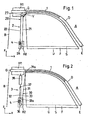
- FIG. 1 shows a view of the side body of a motor vehicle in the region of a front side window F. This is bounded upwards and forwards by the roof edge portion D of the motor vehicle, which - with respect to the vehicle longitudinal axis x - extends forward to the A-pillar of the motor vehicle. To the rear, the front side window F is bounded by the vertical (along the vertical axis of the vehicle z) extending B-pillar and down in the usual way by a door sill.
- an airbag module is arranged in a known manner, which comprises a gas bag 1 extending in the folded state along the entire roof edge region D enclosing the front side window F. This is inflatable by means of a gas generator G, which is attached to a arranged at the upper end of the B-pillar retaining plate H1.
- the front end of the lower edge of the airbag (corresponding to the front end of the tension line S) fixed at the front, lower end E of the roof edge region D set.
- the rear end of the lower edge of the airbag 1 is in contrast connected by means of a connecting element V with a first portion 21 of an elongated element 20 in the form of a closed loop forming rope which forms part of a guide means 2 for guiding the rear end of the lower edge of the airbag during deployment of the gas bag forms.
- the cable 20 is guided by means of two deflecting elements 26, 27 such that a section 21 of the cable 20 extends adjacent to the rear edge of the window pane F and another section 22 of the cable extends on the side of the first section 21 facing away from the window pane F.
- Both sections 21, 22 of the cable 20 extend substantially parallel to the vertical vehicle axis z along the B-pillar B.
- a greater inclination of at least one of the sections 21, 22 of the Rope 20 be advantageous to the vertical axis of the vehicle z, as shown below FIG. 2 will become clear.
- the lower of the two along the vertical axis of the vehicle z spaced deflecting elements 26, 27 is arranged on a holding plate H2 (holding plate), which is arranged on the B-pillar B approximately at the level of the lower pane edge U.
- the other deflecting element 27 is arranged on the holding plate H1, which also serves to receive the gas generator G.
- the deflecting elements may be, for example, rotatably mounted pulleys.
- a backstop 4 is arranged on the lower holding plate H2, which allows a movement of the cable 20 in such a way that the first cable section 21 (along the deployment direction of the airbag 1) moves downward and the second cable section 22 in the opposite direction upwards while a movement of the cable 20 is locked in the reverse direction.
- the airbag 1 is inflated by gases flowing out of the gas generator G and he unfolds from the roof edge portion D down towards the lower edge U of the front side window F.
- the rear end of the lower edge of the airbag 1 which is connected via a connecting element V with the first portion 21 of the cable 20, guided precisely along the path defined by the cable section 21.
- this cable section 21 moves downwards due to the forces acting down upon deployment of the airbag 1 together with the rear end of the lower edge of the airbag 1, ie, the loop 20 forming a loop is rotated clockwise about the deflection elements 26 configured as pulleys. 27 moves.
- first cable section 21 and the second cable section 22 each denote that section of the cable which lies opposite the front side window F or the front side window F. That is to say, the areas of the cable 20 which respectively support the first cable section 21 and the first cable section 21 form second cable section 22, change during a movement of the cable 20 about the deflecting elements 26, 27.
- the lower edge of the airbag 1 is then along the line of tension S between the front lower end E of the roof edge region D, where the front end of the lower edge of the airbag 1 is fixed, and the lower end of the first cable section 21, where the rear end of the lower edge of the airbag 1 is fixed, strained and thereby tightened.
- FIG. 2 illustrated embodiment differs from that in FIG. 1 shown in the training of the guide device 3, which serves to guide the rear end of the lower edge of the airbag 1 along the B-pillar B.
- the guide device 3 comprises an elongate element 30 in the form of a cable, whose one section 31 is guided along the trailing edge of the front side window F and which is fastened with a free end 31 a at the rear end of the lower edge of the airbag 1.
- the first cable section 31 is deflected in such a way that a second cable section 32 extends parallel to the vertical vehicle axle up to the lower free end 37 of a tension spring 38 on the side of the first cable section 31 facing away from the window pane F. , which is fastened at its other end to the upper holding plate H1, which serves to receive the gas generator G.
- the cable 30 is deflected again, so that from there a further cable section 33 extends to the lower holding plate H2, at which that cable section 33 is fixed with its free end 33a.
- FIG. 2 shown embodiment Another special feature of in FIG. 2 shown embodiment is that the first cable section 31 is not exactly parallel to the vertical vehicle axis z or to the rear edge of the window F, but rather is slightly inclined backwards. As a result, the lower edge of the airbag 1 during deployment of the airbag is additionally tightened, as will be explained below.
- the gas bag 1 is filled by means of the gas generator G with gas, wherein the gas bag 1 unfolds in the direction of the lower edge U of the front side window F.
- the tension spring 38 connected to the one free end 31a of the first cable section 31 rear end of the lower edge of the airbag 1 in the direction of the lower deflecting element 36 of the guide device 3 moves. Since this movement does not take place exactly parallel to the vertical vehicle axis z, but rather additionally has a component towards the rear (along the vehicle longitudinal direction x, directed towards the rear of the corresponding vehicle), the lower edge of the airbag 1 becomes the lower edge due to the associated displacement of the rear end in addition tightened and thereby stretched.
- a backstop 4 which is arranged on the lower plate H2, a return of the cable 30 after deployment of the airbag 1, so that the lower edge of the airbag 1 permanently along the tension line S between the front lower end E of the roof edge region D and the lower deflecting element 36 is clamped.
- FIG. 2 illustrated embodiments of an airbag assembly is in each case the leadership of the airbag (in the region of its rear lower end) according to the "flagpole principle" what the each serving as a tensioning flexible traction means in the form of a cable 20, 30 by means of two deflection elements 26, 27 and 36, 37 out is, in the deployment direction of the airbag 1 (ie, along the vertical axis of the vehicle z) spaced from each other with a portion H1, H2 of the vehicle body are connected.
- the respective cable 20, 30 is already guided before unfolding of the airbag 1 (ie in the initial state before triggering of the gas generator) between the respective deflection elements 26, 27 and 36, 37. After triggering the airbag module and during deployment of the airbag 1, only one other section of the cable 20 or 30 then moves into the area between the two deflecting elements 26, 27 or 36, 37, wherein the rear lower end of the airbag 1 is taken down.
- a deflecting element cf., the upper deflecting element 37 in the exemplary embodiment according to FIG. 2
- another assembly eg, a tension spring 38
- the gas bag 1 here preferably consists of one or more parts of fabric which are sewn together to form a closed working space of the airbag. Trained as a rope or band elongate member may for example consist of plastic or woven material.
- FIGS. 3 to 5b illustrated connections between a gas bag and an elongated element in the form of a rope are particularly suitable for such cases in which the cable 20 forms a closed loop of rope.
- This closed loop is by connecting, z. B. welding, the two free ends of a rope.
- a thickening 201 is formed, which is welded to a portion of the airbag 1.
- FIG. 4 is at a portion of the rope 20 a broadening, z. B. in the form of a flag 202, which is sewn by means of a seam 101 with a portion of the airbag 1.
- FIG. 5a is attached to a portion of the airbag cover 1 by means of a seam 51, a portion 50 of a clip element 5, which surrounds the cable 20 with a resiliently shaped end portion 55 into which the cable 20 through an opening 56 by spreading the resilient portion 55 is inserted.
- FIG. 5b an arrangement is shown in which the gas bag 1 has a passage opening 102, in which a provided with an insertion 61 section 60 of a Klips institutes 6 is threaded, which surrounds the cable 20 with another section 65.
- a bracket 204 is provided on the cable 20, to which the two free ends 210, 220 are attached to form a cable loop.
- a section 203 of the cable 20 is additionally looped around a dart 103 of the airbag 1, so that the cable 20 is connected thereto with the gas bag 1.
- the two free ends 210, 220 of an elongate element 20 designed as a band are connected at a fastening point by means of a seam 104 to the casing of an airbag 1.
- the two free ends 210, 220 of a cable 20 are each provided with a thickening 211 or 221, by means of which they are held in a form-fitting manner in corresponding bulges 71, 72 of the base body 70 of a clip element 7.
- the clip element 7 has two clip sections 73, 74 lying opposite one another, each of which engages around an edge of a pocket 105 in a form-fitting manner, which is fastened to the envelope of an airbag 1 by means of a seam 106.
- FIG. 8b is also attached to the shell of a gas bag 1 by means of a seam 106, a pocket 105 which is penetrated by an end portion 210 of the cable 20, while the other end portion 220 of the cable 20 is guided externally on the pocket 105.
- the two end portions 210, 220 of the cable 20 are connected to each other at two attachment points 8a, 8b spaced apart along the extension direction of the cable 20 on both sides of the pocket 105, so that the pocket 105 between the two end portions 210, 220 of the cable 20 and the associated fasteners 8a, 8b is received positively.
- an integrally formed on the shell of the airbag 1 pocket 107 is penetrated by a strand 20a of a rope 20 formed from two strands 20a, 20b, so that the pocket 107 is positively received between the two strands 20a, 20b.
Landscapes
- Engineering & Computer Science (AREA)
- Mechanical Engineering (AREA)
- Air Bags (AREA)
Claims (21)
- Dispositif de protection de passager de véhicule comprenant un sac gonflable, qui doit être agencé sur une carrosserie de véhicule au niveau du bord latéral du toit du véhicule et qui, lorsqu'il est gonflé, se déploie du bord du toit vers le bas pour protéger un passager de véhicule, de telle sorte qu'à l'état gonflé, il s'étend au moins devant une vitre latérale du véhicule, sachant que le bord supérieur du sac gonflable s'étend le long du bord du toit et que le bord inférieur du sac gonflable s'étend en dessous du bord du toit, comprenant également des moyens de guidage qui, lors du gonflement, guident le bord inférieur du sac gonflable dans le sens de déploiement, sachant que le bord inférieur du sac gonflable (1) est rattaché à un tronçon (21, 31) d'un élément long (20, 30), guidé de façon mobile dans le sens de déploiement du sac gonflable (1) sur la carrosserie du véhicule, sachant que l'élément long (20, 30) est guidé au moyen de deux éléments de renvoi (26, 27 ; 36, 37), qui sont séparés le long du sens de déploiement (z) du sac gonflable (1) et sont liés à chacune d'une partie de la carrosserie (H1, H2), le mouvement de l'élément long (20, 30) est provoqué dans le sens de déploiement par le sac gonflable (1) se déployant et où l'élément long (20, 30) est guidé de manière définie par les éléments de renvoi (26, 27 ; 36, 37) préalablement au déploiement du sac gonflable (1), caractérisé en ce que l'élément long (20, 30) est guidé et tendu de façon que lors du gonflement et du déploiement du sac gonflable (1) aucune déviation significative de l'élément long (20, 30) perpendiculairement à sa direction d'étendue n'est produite.
- Dispositif de protection de passager de véhicule selon la revendication 1, caractérisé en ce que l'élément long (20, 30) est formé au moyen d'un moyen de traction flexible.
- Dispositif de protection de passager de véhicule selon la revendication 1 ou 2, caractérisé en ce que l'élément long (20, 30) est formé au moyen d'un câble ou d'une courroie.
- Dispositif de protection de passager de véhicule selon l'une quelconque des revendications précédentes, caractérisé en ce qu'il est muni d'un cliquet anti-retour (4) permettant d'éviter un mouvement de l'élément long (20, 30) dans le sens inverse de son mouvement lors du déploiement du sac gonflable.
- Dispositif de protection de passager de véhicule selon la revendication 4, caractérisé en ce que le cliquet anti-retour (4) est agencé à côté d'un élément de renvoi (26, 36).
- Dispositif de protection de passager de véhicule selon l'une quelconque des revendications précédentes, caractérisé en ce que l'élément le plus long (20) est formé comme un noeud coulant fermé.
- Dispositif de protection de passager de véhicule selon l'une quelconque des revendications 1 à 5, caractérisé en ce que l'élément long (30) est rattaché par une extrémité (31a) au sac gonflable (1) et par l'autre extrémité (33a) à une pièce fixée à la carrosserie (H2).
- Dispositif de protection de passager de véhicule selon l'une des revendications précédentes, caractérisé en ce que au moins un élément de renvoi (26, 27 ; 36) est rattaché directement à une pièce fixée à la carrosserie (H1, H2).
- Dispositif de protection de passager de véhicule selon l'une des revendications précédentes, caractérisé en ce que au moins un élément de renvoi (37) est rattaché à une pièce fixée à la carrosserie (H1) par l'intermédiaire d'un groupe d'assemblage supplémentaire (38).
- Dispositif de protection de passager de véhicule selon l'une quelconque des revendications précédentes, caractérisé en ce qu'une force élastique facilite le mouvement du tronçon (31) de l'élément long (30) dans le sens de déploiement du sac gonflable (1).
- Dispositif de protection de passager de véhicule selon la revendication 10, caractérisé en ce que l'élément le plus long (30) est tendu au moyen de la force élastique.
- Dispositif de protection de passager de véhicule selon l'une quelconque des revendications précédentes, caractérisé en ce que le tronçon (31) de l'élément long (30) est guidé de façon inclinée relativement au sens principal de déploiement (z) du sac gonflable (1) de telle manière que le bord inférieur du sac gonflable (1) est tendu plus fermement au fur et à mesure du déploiement du sac gonflable (1).
- Dispositif de protection de passager de véhicule selon l'une quelconque des revendications précédentes, caractérisé en ce que au moins une partie des moyens de guidage (2, 3) du bord inférieur du sac gonflable (1) est agencée sur une plaque de support (H1) pour un générateur de gaz (G) pour le gonflement du sac gonflable (1).
- Dispositif de protection de passager de véhicule selon l'une quelconque des revendications précédentes, caractérisé en ce que le bord inférieur du sac gonflable (1) est guidé par une extrémité par les moyens de guidage (2, 3) lors du déploiement et est fixé à la carrosserie par l'autre extrémité.
- Dispositif de protection de passager de véhicule selon l'une quelconque des revendications précédentes, caractérisé en ce que les moyens de guidage (2, 3) sont prévus sur une colonne verticale (B) du véhicule.
- Dispositif de protection de passager de véhicule selon l'une quelconque des revendications précédentes, caractérisé en ce qu'une liaison indétachable est utilisée pour la jonction de l'élément long (20, 30) avec le sac gonflable (1).
- Dispositif de protection de passager de véhicule selon la revendication 16, caractérisé en ce que la liaison indétachable est réalisée par soudage, par collage ou par piquage.
- Dispositif de protection de passager de véhicule selon l'une quelconque des revendications 1 à 15, caractérisé en ce que l'élément long (20, 30) est rattaché au sac gonflable (1) de façon détachable.
- Dispositif de protection de passager de véhicule selon la revendication 18, caractérisé en ce que la liaison entre l'élément long (20, 30) et le sac gonflable (1) est réalisée au moyen d'un élément clip (5, 6, 7).
- Dispositif de protection de passager de véhicule selon la revendication 18, caractérisé en ce que l'élément long (20, 30) maintient étroitement le sac gonflable (1) au niveau d'une zone prévue à cet effet (103, 105, 107).
- Dispositif de protection de passager de véhicule selon l'une quelconque des revendications précédentes, caractérisé en ce que le sac gonflable (1) est muni d'une ouverture (102) ou d'une poche (103, 105, 107) destinée à la liaison du sac gonflable (1) avec l'élément long (20, 30).
Applications Claiming Priority (2)
| Application Number | Priority Date | Filing Date | Title |
|---|---|---|---|
| DE10229102 | 2002-06-25 | ||
| DE10229102A DE10229102A1 (de) | 2002-06-25 | 2002-06-25 | Insassenschutzeinrichtung für Kraftfahrzeuginsassen |
Publications (3)
| Publication Number | Publication Date |
|---|---|
| EP1375263A1 EP1375263A1 (fr) | 2004-01-02 |
| EP1375263B1 EP1375263B1 (fr) | 2005-07-27 |
| EP1375263B2 true EP1375263B2 (fr) | 2008-10-29 |
Family
ID=29716714
Family Applications (1)
| Application Number | Title | Priority Date | Filing Date |
|---|---|---|---|
| EP03090171A Expired - Lifetime EP1375263B2 (fr) | 2002-06-25 | 2003-06-05 | Disposittif de protection de passager de vehicule |
Country Status (5)
| Country | Link |
|---|---|
| US (1) | US6994371B2 (fr) |
| EP (1) | EP1375263B2 (fr) |
| JP (1) | JP4340487B2 (fr) |
| CN (1) | CN100361844C (fr) |
| DE (2) | DE10229102A1 (fr) |
Families Citing this family (14)
| Publication number | Priority date | Publication date | Assignee | Title |
|---|---|---|---|---|
| GB2387150B (en) * | 2002-04-05 | 2005-08-24 | Autoliv Dev | Improvements in or relating to motor vehicle safety devices |
| US6964431B2 (en) * | 2002-09-30 | 2005-11-15 | Tk Holdings, Inc. | Loop cord slide device for airbag |
| JP4269928B2 (ja) * | 2003-12-19 | 2009-05-27 | タカタ株式会社 | カーテンエアバッグのガイド装置及びカーテンエアバッグ装置 |
| JP2006131104A (ja) * | 2004-11-05 | 2006-05-25 | Takata Corp | カーテンエアバッグ装置 |
| US20070018442A1 (en) * | 2005-07-22 | 2007-01-25 | Kwok Ming Y | Vehicle driver and passenger restraining device |
| JP2007145308A (ja) * | 2005-11-07 | 2007-06-14 | Toyoda Gosei Co Ltd | 乗員保護装置 |
| DE202006010362U1 (de) | 2006-06-29 | 2006-09-14 | Takata-Petri Ag | Seitengassackanordnung |
| US7712773B2 (en) * | 2006-11-06 | 2010-05-11 | Autoliv Asp, Inc. | Cinch ring for tightening tethers of an inflatable airbag |
| JP5814011B2 (ja) * | 2011-06-29 | 2015-11-17 | セーレン株式会社 | カーテンエアバッグ |
| KR102227852B1 (ko) * | 2014-10-29 | 2021-03-15 | 현대모비스 주식회사 | 커튼 에어백 장치 및 그것의 제조방법 |
| TWI616363B (zh) * | 2016-06-27 | 2018-03-01 | Liu Jun Nan | Vehicle defense personnel |
| KR102514344B1 (ko) * | 2018-11-07 | 2023-03-27 | 현대모비스 주식회사 | 루프 에어백 장치 |
| US11148631B2 (en) * | 2019-10-02 | 2021-10-19 | Ford Global Technologies, Llc | Vehicle airbag |
| FR3103762B1 (fr) * | 2019-11-28 | 2022-06-03 | Psa Automobiles Sa | Déflecteur pour coussin gonflable de sécurité de type rideau |
Citations (2)
| Publication number | Priority date | Publication date | Assignee | Title |
|---|---|---|---|---|
| DE29903778U1 (de) † | 1999-03-02 | 1999-07-01 | Trw Repa Gmbh | Seitenaufprall-Schutzeinrichtung |
| DE10129581A1 (de) † | 2000-07-05 | 2002-02-14 | Trw Vehicle Safety Systems | Aufblasbarer Vorhang mit gleit- oder verschiebbarem Fangband |
Family Cites Families (22)
| Publication number | Priority date | Publication date | Assignee | Title |
|---|---|---|---|---|
| US3361068A (en) * | 1966-08-18 | 1968-01-02 | Allis Chalmers Mfg Co | Double hydraulic pump with built-in unloading valve |
| JPH06344841A (ja) * | 1993-06-11 | 1994-12-20 | Honda Motor Co Ltd | 車両用乗員保護装置 |
| DE4420125C2 (de) | 1993-07-29 | 1996-01-25 | Fichtel & Sachs Ag | Drehgriffschalter für Fahrräder |
| DE19519297A1 (de) | 1994-06-03 | 1995-12-07 | Volkswagen Ag | Sicherheitseinrichtung für ein Fahrzeug |
| GB2333075B (en) * | 1995-02-20 | 1999-08-25 | Autoliv Dev | Improvements in or relating to a safety device |
| JPH09249089A (ja) * | 1996-03-15 | 1997-09-22 | Tokai Rika Co Ltd | エアバッグ装置 |
| DE29605896U1 (de) * | 1996-03-29 | 1996-07-25 | Trw Occupant Restraint Systems Gmbh, 73551 Alfdorf | Seitenaufprall-Schutzeinrichtung für Fahrzeuginsassen |
| DE29615485U1 (de) * | 1996-09-05 | 1997-01-09 | Trw Repa Gmbh | Rückhaltesystem für Fahrzeuginsassen |
| GB9619613D0 (en) * | 1996-09-19 | 1996-10-30 | Breed Automotive Tech | An inflatable restraint for a vehicle |
| DE19654490C2 (de) * | 1996-12-17 | 2000-01-05 | Petri Ag | Airbag, insbesondere Seitenairbag |
| DE19707347C2 (de) * | 1996-12-17 | 2001-03-01 | Petri Ag | Airbag, insbesondere Seitenairbag |
| DE59711719D1 (de) * | 1996-12-21 | 2004-07-22 | Volkswagen Ag | Seitenairbagsystem für ein Kraftfahrzeug |
| JP2000006748A (ja) * | 1998-06-19 | 2000-01-11 | Toyota Motor Corp | 頭部保護エアバッグ装置 |
| DE19843402C1 (de) * | 1998-09-22 | 2000-03-16 | Daimler Chrysler Ag | Seitenaufprall-Airbageinrichtung |
| DE19926269B4 (de) * | 1999-06-10 | 2004-07-15 | Daimlerchrysler Ag | Schutzvorrichtung für den Kopf- und Schulterbereich von Fahrzeuginsassen |
| US6168193B1 (en) * | 1999-08-05 | 2001-01-02 | Trw Inc. | Inflatable curtain with tensioning device |
| US6237938B1 (en) * | 1999-09-01 | 2001-05-29 | Trw Vehicle Safety Systems Inc. | Inflatable curtain with anchor device |
| JP2001071856A (ja) * | 1999-09-03 | 2001-03-21 | Toyota Motor Corp | 頭部保護エアバッグ装置 |
| US6412810B1 (en) * | 1999-11-04 | 2002-07-02 | Breed Automotivetechnology, Inc. | Inflatable side air bag curtain module |
| US6361068B1 (en) * | 2000-05-23 | 2002-03-26 | Trw Vehicle Safety Systems Inc. | Folded inflatable side curtain with tether |
| US6237943B1 (en) * | 2000-10-07 | 2001-05-29 | Ford Global Technologies, Inc. | Vehicle rollover curtain with improved deployment |
| US6474678B1 (en) * | 2001-10-23 | 2002-11-05 | Trw Vehicle Safety System Inc. | Tether attachment for multi-layered inflatable curtain |
-
2002
- 2002-06-25 DE DE10229102A patent/DE10229102A1/de not_active Withdrawn
-
2003
- 2003-06-05 EP EP03090171A patent/EP1375263B2/fr not_active Expired - Lifetime
- 2003-06-05 DE DE50300842T patent/DE50300842D1/de not_active Expired - Lifetime
- 2003-06-24 JP JP2003204133A patent/JP4340487B2/ja not_active Expired - Fee Related
- 2003-06-24 US US10/602,004 patent/US6994371B2/en not_active Expired - Fee Related
- 2003-06-25 CN CNB031478212A patent/CN100361844C/zh not_active Expired - Fee Related
Patent Citations (2)
| Publication number | Priority date | Publication date | Assignee | Title |
|---|---|---|---|---|
| DE29903778U1 (de) † | 1999-03-02 | 1999-07-01 | Trw Repa Gmbh | Seitenaufprall-Schutzeinrichtung |
| DE10129581A1 (de) † | 2000-07-05 | 2002-02-14 | Trw Vehicle Safety Systems | Aufblasbarer Vorhang mit gleit- oder verschiebbarem Fangband |
Also Published As
| Publication number | Publication date |
|---|---|
| CN1475388A (zh) | 2004-02-18 |
| CN100361844C (zh) | 2008-01-16 |
| EP1375263B1 (fr) | 2005-07-27 |
| EP1375263A1 (fr) | 2004-01-02 |
| US6994371B2 (en) | 2006-02-07 |
| JP4340487B2 (ja) | 2009-10-07 |
| JP2004249967A (ja) | 2004-09-09 |
| US20040056457A1 (en) | 2004-03-25 |
| DE10229102A1 (de) | 2004-01-29 |
| DE50300842D1 (de) | 2005-09-01 |
Similar Documents
| Publication | Publication Date | Title |
|---|---|---|
| EP1048531B1 (fr) | Dispositif de protection contre le choc latéral pour les occupants d'un véhicule | |
| EP1386792B1 (fr) | Dispositif de protection d'un passager dans un véhicule | |
| DE19632222B4 (de) | Innenverkleidung für ein Fahrzeugdach | |
| EP1375263B2 (fr) | Disposittif de protection de passager de vehicule | |
| EP0957008B1 (fr) | Dispositif de protection à l'égard d' impacts latéraux | |
| EP1053132B1 (fr) | Installation de retenue pourvue d'un dispositif de tension | |
| DE10306343B4 (de) | Insassenschutzeinrichtung | |
| EP0875426A2 (fr) | Coussin gonflable en forme de rideau, en particulier pour une vitre de véhicule | |
| DE102005011676A1 (de) | Vorhang-Gassack und Kraftfahrzeug | |
| DE102010049112B4 (de) | Beschlagteil zur Befestigung eines Spannbandes eines Vorhanggassackes an einem Fahrzeugteil | |
| DE19654490C2 (de) | Airbag, insbesondere Seitenairbag | |
| EP1059209B1 (fr) | Dispositif de protection de la tête et de l' épaule d'un occupant de véhicule | |
| EP1278660A2 (fr) | Dispositif de protection laterale pour vehicules | |
| EP3883820B1 (fr) | Module airbag pour un véhicule automobile | |
| WO2006069669A1 (fr) | Systeme d'airbag pour vehicules automobiles | |
| DE19542436A1 (de) | Airbagvorrichtung für ein Kraftfahrzeug | |
| DE29705489U1 (de) | Seitenaufprall-Schutzeinrichtung | |
| DE10134802C2 (de) | Curtain-Airbag-Modul | |
| DE102017117103A1 (de) | Fahrzeuginsassenschutzsystem mit einem Gassackmodul | |
| DE102006049431A1 (de) | Airbag | |
| DE102015214354B4 (de) | Gassackanordnung für ein Kraftfahrzeug | |
| DE102014000317A1 (de) | Airbag-Anordnung | |
| DE202004019790U1 (de) | Gassackeinrichtung mit A-Säulen-Abdeckung | |
| AT5690U1 (de) | Anordnung zum verbinden der endbereiche zweier innenverkleidungsteile für ein kraftfahrzeug | |
| DE102005047693B4 (de) | Gassackvorrichtung mit einem aufblasbaren Gassack und einem in dem Gassack angeordneten, faltbaren Füllschlauch |
Legal Events
| Date | Code | Title | Description |
|---|---|---|---|
| PUAI | Public reference made under article 153(3) epc to a published international application that has entered the european phase |
Free format text: ORIGINAL CODE: 0009012 |
|
| AK | Designated contracting states |
Kind code of ref document: A1 Designated state(s): AT BE BG CH CY CZ DE DK EE ES FI FR GB GR HU IE IT LI LU MC NL PT RO SE SI SK TR |
|
| AX | Request for extension of the european patent |
Extension state: AL LT LV MK |
|
| 17P | Request for examination filed |
Effective date: 20040701 |
|
| AKX | Designation fees paid |
Designated state(s): DE FR GB SE |
|
| GRAP | Despatch of communication of intention to grant a patent |
Free format text: ORIGINAL CODE: EPIDOSNIGR1 |
|
| GRAS | Grant fee paid |
Free format text: ORIGINAL CODE: EPIDOSNIGR3 |
|
| GRAA | (expected) grant |
Free format text: ORIGINAL CODE: 0009210 |
|
| AK | Designated contracting states |
Kind code of ref document: B1 Designated state(s): DE FR GB SE |
|
| REG | Reference to a national code |
Ref country code: GB Ref legal event code: FG4D Free format text: NOT ENGLISH |
|
| REF | Corresponds to: |
Ref document number: 50300842 Country of ref document: DE Date of ref document: 20050901 Kind code of ref document: P |
|
| REG | Reference to a national code |
Ref country code: SE Ref legal event code: TRGR |
|
| GBT | Gb: translation of ep patent filed (gb section 77(6)(a)/1977) |
Effective date: 20051109 |
|
| ET | Fr: translation filed | ||
| PLBI | Opposition filed |
Free format text: ORIGINAL CODE: 0009260 |
|
| PLAX | Notice of opposition and request to file observation + time limit sent |
Free format text: ORIGINAL CODE: EPIDOSNOBS2 |
|
| 26 | Opposition filed |
Opponent name: AUTOLIV DEVELOPEMENT AB Effective date: 20060426 |
|
| PLAF | Information modified related to communication of a notice of opposition and request to file observations + time limit |
Free format text: ORIGINAL CODE: EPIDOSCOBS2 |
|
| PLBB | Reply of patent proprietor to notice(s) of opposition received |
Free format text: ORIGINAL CODE: EPIDOSNOBS3 |
|
| PUAH | Patent maintained in amended form |
Free format text: ORIGINAL CODE: 0009272 |
|
| STAA | Information on the status of an ep patent application or granted ep patent |
Free format text: STATUS: PATENT MAINTAINED AS AMENDED |
|
| 27A | Patent maintained in amended form |
Effective date: 20081029 |
|
| AK | Designated contracting states |
Kind code of ref document: B2 Designated state(s): DE FR GB SE |
|
| PGFP | Annual fee paid to national office [announced via postgrant information from national office to epo] |
Ref country code: SE Payment date: 20080624 Year of fee payment: 6 |
|
| PGFP | Annual fee paid to national office [announced via postgrant information from national office to epo] |
Ref country code: GB Payment date: 20080624 Year of fee payment: 6 |
|
| GBPC | Gb: european patent ceased through non-payment of renewal fee |
Effective date: 20090605 |
|
| PG25 | Lapsed in a contracting state [announced via postgrant information from national office to epo] |
Ref country code: GB Free format text: LAPSE BECAUSE OF NON-PAYMENT OF DUE FEES Effective date: 20090605 |
|
| PGFP | Annual fee paid to national office [announced via postgrant information from national office to epo] |
Ref country code: DE Payment date: 20120530 Year of fee payment: 10 |
|
| PGFP | Annual fee paid to national office [announced via postgrant information from national office to epo] |
Ref country code: FR Payment date: 20120619 Year of fee payment: 10 |
|
| PG25 | Lapsed in a contracting state [announced via postgrant information from national office to epo] |
Ref country code: SE Free format text: LAPSE BECAUSE OF NON-PAYMENT OF DUE FEES Effective date: 20090606 |
|
| REG | Reference to a national code |
Ref country code: DE Ref legal event code: R119 Ref document number: 50300842 Country of ref document: DE Effective date: 20140101 |
|
| REG | Reference to a national code |
Ref country code: FR Ref legal event code: ST Effective date: 20140228 |
|
| PG25 | Lapsed in a contracting state [announced via postgrant information from national office to epo] |
Ref country code: DE Free format text: LAPSE BECAUSE OF NON-PAYMENT OF DUE FEES Effective date: 20140101 |
|
| PG25 | Lapsed in a contracting state [announced via postgrant information from national office to epo] |
Ref country code: FR Free format text: LAPSE BECAUSE OF NON-PAYMENT OF DUE FEES Effective date: 20130701 |