EP1375342A1 - Avion à contrôle actif du vrillage de ses ailes - Google Patents
Avion à contrôle actif du vrillage de ses ailes Download PDFInfo
- Publication number
- EP1375342A1 EP1375342A1 EP03291277A EP03291277A EP1375342A1 EP 1375342 A1 EP1375342 A1 EP 1375342A1 EP 03291277 A EP03291277 A EP 03291277A EP 03291277 A EP03291277 A EP 03291277A EP 1375342 A1 EP1375342 A1 EP 1375342A1
- Authority
- EP
- European Patent Office
- Prior art keywords
- wing
- aircraft
- plane
- aerodynamic
- flight
- Prior art date
- Legal status (The legal status is an assumption and is not a legal conclusion. Google has not performed a legal analysis and makes no representation as to the accuracy of the status listed.)
- Granted
Links
- 238000000034 method Methods 0.000 claims abstract description 8
- 238000012935 Averaging Methods 0.000 claims description 2
- 238000010276 construction Methods 0.000 description 13
- 238000012550 audit Methods 0.000 description 7
- 244000245420 ail Species 0.000 description 6
- 238000005452 bending Methods 0.000 description 4
- 238000004364 calculation method Methods 0.000 description 4
- 229940082150 encore Drugs 0.000 description 4
- 230000005484 gravity Effects 0.000 description 4
- 230000007423 decrease Effects 0.000 description 3
- 230000000694 effects Effects 0.000 description 3
- 238000005259 measurement Methods 0.000 description 3
- 238000001914 filtration Methods 0.000 description 2
- 239000000446 fuel Substances 0.000 description 2
- 238000004519 manufacturing process Methods 0.000 description 2
- 239000003381 stabilizer Substances 0.000 description 2
- 240000008042 Zea mays Species 0.000 description 1
- 230000003416 augmentation Effects 0.000 description 1
- 210000003323 beak Anatomy 0.000 description 1
- 238000010586 diagram Methods 0.000 description 1
- 238000005516 engineering process Methods 0.000 description 1
- 235000021183 entrée Nutrition 0.000 description 1
- 230000006353 environmental stress Effects 0.000 description 1
- 230000033001 locomotion Effects 0.000 description 1
- 239000003607 modifier Substances 0.000 description 1
- 244000045947 parasite Species 0.000 description 1
- 230000035882 stress Effects 0.000 description 1
Images


Classifications
-
- B—PERFORMING OPERATIONS; TRANSPORTING
- B64—AIRCRAFT; AVIATION; COSMONAUTICS
- B64C—AEROPLANES; HELICOPTERS
- B64C23/00—Influencing air flow over aircraft surfaces, not otherwise provided for
- B64C23/06—Influencing air flow over aircraft surfaces, not otherwise provided for by generating vortices
- B64C23/065—Influencing air flow over aircraft surfaces, not otherwise provided for by generating vortices at the wing tips
- B64C23/069—Influencing air flow over aircraft surfaces, not otherwise provided for by generating vortices at the wing tips using one or more wing tip airfoil devices, e.g. winglets, splines, wing tip fences or raked wingtips
- B64C23/072—Influencing air flow over aircraft surfaces, not otherwise provided for by generating vortices at the wing tips using one or more wing tip airfoil devices, e.g. winglets, splines, wing tip fences or raked wingtips the wing tip airfoil devices being moveable in their entirety
-
- B—PERFORMING OPERATIONS; TRANSPORTING
- B64—AIRCRAFT; AVIATION; COSMONAUTICS
- B64C—AEROPLANES; HELICOPTERS
- B64C3/00—Wings
- B64C3/38—Adjustment of complete wings or parts thereof
- B64C3/52—Warping
-
- B—PERFORMING OPERATIONS; TRANSPORTING
- B64—AIRCRAFT; AVIATION; COSMONAUTICS
- B64C—AEROPLANES; HELICOPTERS
- B64C5/00—Stabilising surfaces
- B64C5/08—Stabilising surfaces mounted on, or supported by, wings
-
- Y—GENERAL TAGGING OF NEW TECHNOLOGICAL DEVELOPMENTS; GENERAL TAGGING OF CROSS-SECTIONAL TECHNOLOGIES SPANNING OVER SEVERAL SECTIONS OF THE IPC; TECHNICAL SUBJECTS COVERED BY FORMER USPC CROSS-REFERENCE ART COLLECTIONS [XRACs] AND DIGESTS
- Y02—TECHNOLOGIES OR APPLICATIONS FOR MITIGATION OR ADAPTATION AGAINST CLIMATE CHANGE
- Y02T—CLIMATE CHANGE MITIGATION TECHNOLOGIES RELATED TO TRANSPORTATION
- Y02T50/00—Aeronautics or air transport
- Y02T50/10—Drag reduction
Definitions
- the present invention relates to twisting wings of aircraft and, in particular, the control of this twisting in flight.
- each wing of an airplane consists of a plurality elementary aerodynamic profiles, angularly wedged respectively relative to a reference axis to give said wing a reference twisting.
- a reference twist is theoretically determined in order to optimize the performance of said wing, particularly in regarding the distribution of aerodynamic loads in wingspan and the reduction of induced drag, at a specific point of flight, usually chosen to match the middle of the plane's cruise.
- the present invention aims to overcome this disadvantage.
- the present invention is based on the fact that the arrow of said plane additional aerodynamics being greater than that of the wing, the result is a decline in the center of pressures of this plan.
- the forces aerodynamic generated by it namely essentially a lift and a drag
- Such a moment has the effect of twisting the wing, which affects twisting of it.
- at each angular position of the aerodynamic plane additional is an orientation and a position of the said forces aerodynamic, that is to say a value of said moment exerted on the end of the wing and therefore an amplitude of the torsion exerted on the wing. So, at each angular position of said plane is associated, for a point of flight in particular, a specific twisting of said wing.
- each additional aerodynamic plane is soaring in relation to at the trailing edge of the corresponding wing.
- said line of articulation of the aerodynamic plane addition of the invention is at least substantially parallel to the longitudinal axis from the plane.
- said additional aerodynamic plane can occupy a deployment position for which he is in continuation of the extrados of said wing. So, at the low speeds of the plane, said additional aerodynamic plane can provide additional surface bearing.
- the aircraft comprises at the end of a wing a system of pinnae (usually called “winglet” in the aerodynamic technique) to reduce wing tip swirling phenomena
- said additional aerodynamic plane is advantageous for said additional aerodynamic plane to be constituted by one of the plans of said pennes system.
- the plane is provided with at least one sensor for each of said parameters and the measurements of said sensors are addressed to said table, which then delivers a first signal representative of the optimal angle of rotation.
- This signal is addressed to said actuating means, which actuate accordingly said aerodynamic plane additional.
- the measuring device delivering said third signal can include, for example, an accelerometer placed at said aerodynamic profile particular elementary measure, whose measurements are compared with those of a other accelerometer placed in the fuselage of the aircraft, which allows to obtain the kinking of said particular elementary aerodynamic profile.
- said signal representative of the comparison is multiplied by a gain, that said second and third signals are averaged or not.
- a gain is unique to each plane and it means, if its value is equal to K, it is necessary to steer said additional aerodynamic plane of K degrees to obtain a kinking of 1 degree of said aerodynamic profile particular elementary wing, usually at the free end of it.
- the pivot order transmitted to the plane additional aerodynamics be strongly filtered so that the motions of the latter are slow and independent of the disturbances of the atmosphere and moments of the plane.
- the filtering frequency must be lower at the natural frequencies of the wing. For example, for a big plane civil carrier whose natural frequencies are of the order of 1 hertz, the frequency filtering will be well below one-tenth of a hertz.
- FIG. 1 is a perspective view, from the front and the top, of a commercial aircraft according to the present invention, during flight.
- FIG. 2 is a schematic and partial view of this aircraft, given forward.
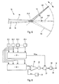
- FIG. 3 is a schematic and partial view of this aircraft, given from above.
- Figure 4 schematically illustrates the twisting of the wings of the aircraft Figures 1 to 3.
- Figure 5 shows, in schematic perspective and larger scale, the quill provided at the free outer end of each wing of the aircraft of Figures 1 to 3.
- Figure 6 is a schematic front view of Figure 5.
- FIGs 7, 8 and 9 are the block diagrams of three modes embodiment of the control means in rotation of the pin of the figures 5 and 6.
- the heavy commercial aircraft 1 according to the present invention and schematically shown in perspective in FIG. an elongated fuselage 2 of longitudinal axis L-L, two wings 3 symmetrically opposed to said fuselage 2, motors 4 suspended from said wings 3, a rear horizontal stabilizer 5 and a rear vertical stabilizer 6.
- the two wings 3 are emplantées in 7 in said fuselage 2. Each of them forms a leading edge 8 forward and a trailing edge 9 towards the rear. In addition, they are arranged in an arrow relative to the fuselage 2 and their width decreases from their root 7 to their outer end 10.
- each of the two wings 3 consists of a plurality of elementary profiles angularly wedged with respect to an axis reference R-R and extending along the span of the corresponding wing 3, so as to give said wings 3 a reference twist.
- This twisting can be characterized by the angle of wedge ⁇ that the rope of the basic elementary profile with the string of a basic elementary profile, such that is illustrated schematically in Figure 4.
- the third profile Elementary 13 whose leading edge is designated 8.13, is at vicinity of the outer end 10 of the corresponding wing 3 at the location line XIII-XIII of Figure 3 and is smaller than the profile element 12.
- the chord C13 of the elementary profile 13 is inclined by the value ⁇ 13 of the angle calibration ⁇ , larger than the value ⁇ 12.
- each of the wings 3 is twisted from its root (profile 11) to its outer end 10, and the further the elementary profile is removed of said root 7, plus its leading edge is oriented towards the low.
- a quill 14 generally referred to as Anglo-Saxon "winglet” in aeronautical technology and intended, in known manner, to reduce drag caused by wingtip vortices.
- the pin 14 is articulated, at the outer end 10 of a wing 3, along a hinge line A-A, at least substantially parallel to the longitudinal axis L-L of the fuselage 2, to be able to take rotated positions 14E directed from the side of the upper surface 15 of the wing 3 and, optionally, a position 14H in extension of the wing 3 or pivoted positions 141 directed to the side of the intrados 16 of said wing.
- the leading edge 17 of the pin 14 is disposed in an arrow relative to the leading edge 8 of the wing 3, the arrow angle being designated by f1.
- the edge of 18 leakage of the pin 14 is disposed in an arrow relative to the trailing edge 9 of the wing 3, the arrow angle being designated by f2.
- actuating means 19, for example of the jack type are connected to the pin 14, for example by a linkage 20 (see FIGS. 6 to 9), to be able to rotate it around said hinge line A-A and thus vary said angle W, as illustrated by the double arrow F.
- FIG. 7 shows a first exemplary embodiment means adapted to control the actuating means 19, 20.
- These control means essentially comprise a table 21, established by calculation or experimentally, giving an optimal value Wopt of said angle W as a function of a plurality of flight parameters, such as those mentioned above, namely: Mach number, altitude, position of center of gravity, mass, mass distribution, temperatures, regime engines.
- the aircraft 1 further comprises a plurality of sensors 22.1 to 22.n measuring the current value of each of the parameters used in the table 21, the measurements of said sensors being addressed to the latter. So, at each instant, the table 21 delivers an optimal value Wopt, corresponding at the current point of flight and the configuration of the airplane (mass, distribution masses, ).
- this device comprises a device 24 (for example of the type mentioned above) capable of delivering a signal representative of the current value ⁇ m of said calibration angle of this particular elemental aerodynamic profile.
- Comparison means 25 compare the signals ⁇ opt and ⁇ m and the result of the comparison is multiplied by a gain K, specific to the aircraft 1, in an amplifier 26, after what it is added in 27 to the Wopt signal from table 21. The sum of signals appearing at the output of the adder 27 is then addressed to the actuating means 19, 20 for the control of the plane additional 14.
- the device of FIG. 9 is similar to that of FIG. 8, except that means 28, 29 and 30 for averaging the signals ⁇ opt, ⁇ m and Wopt are respectively arranged at the inputs of the comparison means 25 and at the output of FIG. the table 21. So these are the signals ⁇ opt , ⁇ m and Wopt , respectively corresponding to the average of the signals ⁇ opt, ⁇ m and Wopt over the same duration, which are used to actuate the pivoting of the additional aerodynamic plane 14.
Landscapes
- Engineering & Computer Science (AREA)
- Aviation & Aerospace Engineering (AREA)
- Mechanical Engineering (AREA)
- Tires In General (AREA)
- Toys (AREA)
- Control Of Turbines (AREA)
- Control Of Position, Course, Altitude, Or Attitude Of Moving Bodies (AREA)
- Pharmaceuticals Containing Other Organic And Inorganic Compounds (AREA)
- Heterocyclic Carbon Compounds Containing A Hetero Ring Having Oxygen Or Sulfur (AREA)
- Walking Sticks, Umbrellas, And Fans (AREA)
Abstract
Description
- à l'extrémité libre externe de ladite aile, on articule au moins un plan aérodynamique additionnel, dont le bord d'attaque est disposé en flèche par rapport au bord d'attaque de ladite aile ; et
- audit point de vol, on impose audit plan aérodynamique additionnel une position angulaire pour laquelle ledit plan aérodynamique additionnel engendre des forces aérodynamiques exerçant une torsion sur ladite aile et amenant celle-ci audit vrillage aérodynamiquement optimal.
- au moins un plan aérodynamique additionnel, articulé à l'extrémité libre externe de ladite aile, le long d'une ligne d'articulation ; et
- des moyens d'actionnement aptes à faire pivoter ledit plan aérodynamique additionnel autour de ladite ligne d'articulation,
- le bord d'attaque de chaque plan aérodynamique additionnel est disposé en flèche par rapport au bord d'attaque de l'aile correspondante ; et
- il est prévu des moyens de commande qui, pour au moins certains points du vol dudit avion, adressent un ordre de pivotement auxdits moyens d'actionnement pour que ceux-ci imposent audit plan aérodynamique additionnel correspondant une position pivotée, pour laquelle ledit plan aérodynamique additionnel engendre des forces aérodynamiques aptes à modifier le vrillage actuel de ladite aile, résultant dudit vrillage de référence, en un vrillage aérodynamiquement optimal pour le point de vol concerné.
- d'optimiser les performances de l'avion, non seulement durant toute la croisière, mais encore dans toute phase de vol dans laquelle on a intérêt à améliorer le vrillage des ailes ;
- d'augmenter la portance, notamment aux basses vitesses ;
- de régler, par de légères dissymétries de braquage pour les plans aérodynamiques additionnels de deux ailes opposées, les inévitables problèmes de dissymétrie de l'avion ; et
- de corriger, par un braquage correctif approprié, les imprécisions de construction et d'assemblage de ladite aile.
- que, pour obtenir un tel contrôle actif du vrillage d'une aile, on pourrait utiliser les surfaces mobiles (ailerons, becs, volets, ...) usuellement prévus sur une aile. Cependant, il en résulterait une augmentation de traínée inacceptable ; et
- que, par exemple par le brevet allemand DE-A-2 149 956 déposé le 7 octobre 1971, on a déjà prévu d'articuler au moins un plan aérodynamique additionnel à l'extrémité de l'aile d'un avion. Toutefois, dans cette technique connue, un tel plan aérodynamique additionnel n'est utilisé que pour réduire la traínée induite par les tourbillons de bout d'aile. De toute façon, le dispositif de plan aérodynamique additionnel ne serait pas utilisable pour la mise en oeuvre de la présente invention, du fait que le bord d'attaque dudit plan est en prolongement de celui du bord d'attaque de l'aile et non pas en flèche.
- le nombre de Mach, puisque les efforts aérodynamiques et leur répartition dépendent du nombre de Mach ;
- la vitesse puisque, à altitude constante, plus la vitesse augmente, plus la pression dynamique augmente, et plus le dévrillage est important ;
- l'altitude, puisque plus l'altitude augmente, plus la pression dynamique diminue à vitesse constante et moins le dévrillage sera important ;
- la position du centre de gravité de l'avion : en effet, la position de ce centre de gravité impose une répartition de la portance entre les ailes de l'avion et l'empennage horizontal arrière de celui-ci. La variation de la position du centre de gravité de l'avion pendant la croisière, due à la consommation de carburant, impose donc une variation de la répartition de la portance entre les ailes et ledit empennage horizontal ;
- la masse de l'avion et sa répartition, puisque plus la masse de l'avion est importante, plus la force de portance nécessaire à la sustentation de l'avion, et donc la flexion de l'aile et le dévrillage de celle-ci, seront grands. Par ailleurs, la masse de carburant stockée dans les réservoirs d'aile tend à contrecarrer la flexion des ailes vers le haut et tend donc à diminuer le dévrillage des ailes ;
- la température à l'extérieur et à l'intérieur de l'aile ;
- la température à l'extrados et à l'intrados de l'aile ;
- le régime des moteurs, c'est-à-dire la poussée qu'ils exercent.
- lesdits moyens de commande comportent de plus une seconde table apte à délivrer un deuxième signal représentatif de l'angle de calage optimal --en ce qui concerne le vrillage de ladite aile-- d'un profil aérodynamique élémentaire particulier de ladite aile, en fonction de ladite pluralité de paramètres de vol mentionnés ci-dessus ;
- on prévoit, à bord dudit avion, en plus desdits capteurs reliés aux entrées de ladite seconde table, au moins un dispositif de mesure délivrant un troisième signal représentatif de la valeur actuelle dudit angle de calage dudit profil aérodynamique élémentaire particulier, et des moyens de comparaison desdits deuxième et troisième signaux ; et
- lesdits moyens d'actionnement reçoivent, à titre d'ordre de pivotement, la somme dudit premier signal et d'un signal représentatif de la comparaison entre lesdits deuxième et troisième signaux.
Claims (10)
- Procédé pour conférer à une aile d'avion (3) le vrillage aérodynamiquement optimal à un point de vol dudit avion (1),
caractérisé en ce que :à l'extrémité libre externe (10) de ladite aile (3), on articule, autour d'une ligne d'articulation (A-A) au moins sensiblement parallèle à l'axe longitudinal (L-L) dudit avion (1), au moins un plan aérodynamique additionnel (14), dont le bord d'attaque (17) est disposé en flèche par rapport au bord d'attaque (8) de ladite aile (3) ; etaudit point de vol, on impose audit plan aérodynamique additionnel (14) une position angulaire pour laquelle ledit plan aérodynamique additionnel engendre des forces aérodynamiques exerçant une torsion sur ladite aile (3) et amenant celle-ci audit vrillage aérodynamiquement optimal. - Avion (1), dont chacune des ailes (3) est constituée d'une pluralité de profils aérodynamiques élémentaires (11, 12, 13) répartis selon son envergure et respectivement calés angulairement par rapport à un axe de référence (R-R) dudit avion pour conférer à ladite aile un vrillage de référence, ledit avion comportant, pour chaque aile (3) :caractérisé en ce que :au moins un plan aérodynamique additionnel (14), articulé à l'extrémité libre externe (10) de ladite aile (3), le long d'une ligne d'articulation (A-A) au moins sensiblement parallèle à l'axe longitudinal (L-L) dudit avion ; etdes moyens d'actionnement (19, 20) aptes à faire pivoter ledit plan aérodynamique additionnel (14) autour de ladite ligne d'articulation (A-A),le bord d'attaque (17) de chaque plan aérodynamique additionnel (14) est disposé en flèche par rapport au bord d'attaque (8) de l'aile (3) correspondante ; etil est prévu des moyens de commande qui, pour au moins certains points du vol dudit avion, adressent un ordre de pivotement auxdits moyens d'actionnement (19, 20) pour que ceux-ci imposent audit plan aérodynamique additionnel (14) correspondant une position pivotée, pour laquelle ledit plan aérodynamique additionnel (14) engendre des forces aérodynamiques aptes à modifier le vrillage actuel de l'aile, résultant dudit vrillage de référence, en un vrillage aérodynamiquement optimal pour le point de vol concerné.
- Avion selon la revendication 2,
caractérisé en ce que le bord de fuite (18) de chaque plan aérodynamique additionnel (14) est disposé en flèche par rapport au bord de fuite (9) de l'aile (3) correspondante. - Avion selon l'une des revendications 2 ou 3,
caractérisé en ce que ledit plan aérodynamique additionnel (14) peut occuper une position de déploiement (14H) pour laquelle il se trouve en prolongement de l'extrados de ladite aile (3). - Avion selon l'une des revendications 2 à 4,
caractérisé en ce que ledit plan aérodynamique additionnel (14) fait partie d'un système de pennes, prévu pour réduire les phénomènes tourbillonnaires en bout d'aile. - Avion selon l'une des revendications 2 à 5,
caractérisé en ce que :lesdits moyens de commande comportent une première table (21) apte à délivrer un premier signal (Wopt) représentatif d'un angle de pivotement optimal --en ce qui concerne ledit vrillage de l'aile (3)-- dudit plan aérodynamique additionnel (14) en fonction d'une pluralité de paramètres de vol influant sur le vrillage de ladite aile (3) ;au moins un capteur (22.1 à 22.n) pour chacun desdits paramètres est prévu à bord dudit avion, lesdits capteurs étant reliés aux entrées de ladite première table (21) ; etlesdits moyens d'actionnement (19) reçoivent, à titre d'ordre de pivotement, ledit premier signal (Wopt) représentatif d'un angle de pivotement optimal délivré par lesdits moyens de commande. - Avion selon la revendication 6,
caractérisé en ce que :lesdits moyens de commande comportent de plus une seconde table (23) apte à délivrer un deuxième signal (αopt) représentatif de l'angle de calage optimal --en ce qui concerne le vrillage de ladite aile-- d'un profil aérodynamique élémentaire particulier (13) de ladite aile (3), en fonction de ladite pluralité de paramètres de vol influant sur le vrillage de ladite aile (3), lesdits capteurs (21.1 à 22.n) étant reliés aux entrées de ladite table (23) ;il est prévu, à bord dudit avion, un dispositif de mesure (24) délivrant un troisième signal (αm) représentatif de la valeur actuelle dudit angle de calage dudit profil aérodynamique élémentaire particulier (13), et des moyens (25) de comparaison desdits deuxième et troisième signaux ; etlesdits moyens d'actionnement (19) reçoivent, à titre d'ordre de pivotement, la somme dudit premier signal (Wopt) et d'un signal représentatif de la comparaison entre lesdits deuxième et troisième signaux. - Avion selon la revendication 7,
caractérisé en ce que lesdits moyens de commande comportent des moyens de moyennage (28, 29, 30) desdits premier, deuxième et troisième signaux, de sorte que lesdits moyens d'actionnement (19) reçoivent, à titre d'ordre de pivotement, la somme dudit premier signal moyenné (Wopt ) et d'un signal représentant la comparaison entre lesdits deuxième et troisième signaux moyennés (αopt etαm ). - Avion selon l'une des revendications 7 ou 8,
caractérisé en ce que ledit profil aérodynamique élémentaire particulier (13) se trouve au voisinage de l'extrémité externe libre (10) de ladite aile (3). - Avion selon l'une des revendications 7 à 9,
caractérisé en ce que, entre lesdits moyens de comparaison (25) et lesdits moyens d'actionnement (19), ledit signal représentatif de la comparaison est multiplié par un gain (26), propre audit avion.
Applications Claiming Priority (2)
| Application Number | Priority Date | Filing Date | Title |
|---|---|---|---|
| FR0208011A FR2841532B1 (fr) | 2002-06-27 | 2002-06-27 | Avion a controle actif du vrillage de ses ailes |
| FR0208011 | 2002-06-27 |
Publications (2)
| Publication Number | Publication Date |
|---|---|
| EP1375342A1 true EP1375342A1 (fr) | 2004-01-02 |
| EP1375342B1 EP1375342B1 (fr) | 2008-12-10 |
Family
ID=29717115
Family Applications (1)
| Application Number | Title | Priority Date | Filing Date |
|---|---|---|---|
| EP03291277A Expired - Lifetime EP1375342B1 (fr) | 2002-06-27 | 2003-05-28 | Avion à contrôle actif du vrillage de ses ailes |
Country Status (6)
| Country | Link |
|---|---|
| US (1) | US6827314B2 (fr) |
| EP (1) | EP1375342B1 (fr) |
| AT (1) | ATE416971T1 (fr) |
| CA (1) | CA2427357C (fr) |
| DE (1) | DE60325141D1 (fr) |
| FR (1) | FR2841532B1 (fr) |
Cited By (25)
| Publication number | Priority date | Publication date | Assignee | Title |
|---|---|---|---|---|
| WO2004065209A1 (fr) * | 2003-01-23 | 2004-08-05 | Airbus Deutschland Gmbh | Surface efficace en ce qui concerne la mecanique des fluides pour la minimisation de la resistance induite |
| FR2862044A1 (fr) * | 2003-11-06 | 2005-05-13 | Deutsch Zentr Luft & Raumfahrt | Procede pour miminiser la resistance d'un avion en vol |
| EP1531126A1 (fr) * | 2003-11-11 | 2005-05-18 | Airbus UK Limited | Organe aérodynamique disposé à l'extrémité externe d'une aile |
| US7275722B2 (en) | 2003-11-10 | 2007-10-02 | Airbus Uk Limited | Wing tip device |
| WO2009074528A3 (fr) * | 2007-12-10 | 2009-10-15 | Airbus Operations Gmbh | Extension en bout d'aile destinée à réduire des traînées tourbillonnaires d'avions |
| DE102008022452A1 (de) * | 2008-05-08 | 2009-12-03 | Bauhaus Luftfahrt E.V. | Flugzeug mit aktiv steuerbaren Hilfsflügeln |
| US9033282B2 (en) | 2010-07-14 | 2015-05-19 | Airbus Operations Limited | Wing tip device |
| CN104670478A (zh) * | 2013-10-17 | 2015-06-03 | 波音公司 | 翼尖控制系统 |
| EP2727829A3 (fr) * | 2012-10-30 | 2015-08-26 | The Boeing Company | Système de contrôle pour le pliage des bouts d'aile |
| EP2727826A3 (fr) * | 2012-10-30 | 2015-10-21 | The Boeing Company | Ailette d'extrémité de voilure articulée |
| US9211946B2 (en) | 2011-10-01 | 2015-12-15 | The Boeing Company | Wing fold system with latch pins through multiple mating lugs |
| US9290260B2 (en) | 2011-10-01 | 2016-03-22 | The Boeing Company | Wing fold controller |
| US9296469B2 (en) | 2011-10-01 | 2016-03-29 | The Boeing Company | Horizontal folding wingtip |
| US9415857B2 (en) | 2012-10-30 | 2016-08-16 | The Boeing Company | Wing fold system |
| US9469392B2 (en) | 2012-10-30 | 2016-10-18 | The Boeing Company | Wing fold system rotating latch |
| US9499252B2 (en) | 2011-10-01 | 2016-11-22 | The Boeing Company | Wing fold controller |
| EP3177828A4 (fr) * | 2014-08-05 | 2018-06-06 | Ryan Church | Structure dotée d'une dérive rigide adaptée pour traverser un environnement fluide |
| US10005546B2 (en) | 2008-06-20 | 2018-06-26 | Aviation Partners, Inc. | Split blended winglet |
| CN108216572A (zh) * | 2018-01-23 | 2018-06-29 | 中国航空工业集团公司沈阳飞机设计研究所 | 一种多曲轴驱动的柔性翼面组件及具有其的机翼 |
| CN109795670A (zh) * | 2017-11-17 | 2019-05-24 | 空中客车运作有限责任公司 | 对可折叠机翼尖端区段的致动进行控制的方法和控制单元 |
| US10377472B2 (en) | 2011-06-09 | 2019-08-13 | Aviation Partners, Inc. | Wing tip with winglet and ventral fin |
| FR3079209A1 (fr) * | 2018-03-22 | 2019-09-27 | Francois Geli | Avion gros porteur bi-reacteur a voilure non-planaire a geometrie variable |
| US10538307B2 (en) | 2011-10-01 | 2020-01-21 | The Boeing Company | Hinged raked wing tip |
| US11104423B2 (en) | 2017-12-06 | 2021-08-31 | Airbus Operations Gmbh | Wing for an aircraft |
| US11254412B2 (en) | 2019-03-29 | 2022-02-22 | The Boeing Company | Foldable raked wing tips having aerodynamic devices |
Families Citing this family (42)
| Publication number | Priority date | Publication date | Assignee | Title |
|---|---|---|---|---|
| US7475848B2 (en) * | 2003-11-11 | 2009-01-13 | Morgenstern John M | Wing employing leading edge flaps and winglets to achieve improved aerodynamic performance |
| CA2602948A1 (fr) | 2005-05-19 | 2006-11-23 | Airbus Deutschland Gmbh | Concept de bout d'aile variable servant a reduire une charge laterale, a reduire une charge laterale et une charge verticale combinees, et a ameliorer la performance d'un moyen delocomotion |
| DE102005028688A1 (de) * | 2005-05-19 | 2006-11-30 | Airbus Deutschland Gmbh | Konzept eines variablen Winglets zur lateralen Lastenreduktion zur kombinierten lateralen und vertikalen Lastenreduktion und zur Performanceverbesserung von Fortbewegungsmitteln |
| US8544800B2 (en) * | 2005-07-21 | 2013-10-01 | The Boeing Company | Integrated wingtip extensions for jet transport aircraft and other types of aircraft |
| US7798443B2 (en) * | 2006-12-18 | 2010-09-21 | The Boeing Company | Composite material for geometric morphing wing |
| US7744038B2 (en) * | 2007-06-15 | 2010-06-29 | The Boeing Company | Controllable winglets |
| US7900876B2 (en) * | 2007-08-09 | 2011-03-08 | The Boeing Company | Wingtip feathers, including forward swept feathers, and associated aircraft systems and methods |
| US20090084904A1 (en) * | 2007-10-02 | 2009-04-02 | The Boeing Company | Wingtip Feathers, Including Paired, Fixed Feathers, and Associated Systems and Methods |
| US8128035B2 (en) * | 2008-04-15 | 2012-03-06 | The Boeing Company | Winglets with recessed surfaces, and associated systems and methods |
| DK2303685T3 (en) | 2008-06-20 | 2016-01-18 | Aviat Partners Inc | KRUM wingtip |
| DE102009019542A1 (de) * | 2009-04-30 | 2010-11-11 | Airbus Deutschland Gmbh | Nicht-planares Flügelendstück für Tragflügel von Flugzeugen sowie Tragflügel mit einem solchen Flügelendstück |
| US8434293B2 (en) * | 2009-08-06 | 2013-05-07 | The Boeing Company | High stiffness shape memory alloy actuated aerostructure |
| US8894018B2 (en) * | 2009-12-10 | 2014-11-25 | University Of The Witwatersrand | Method for reducing in flight wake vortices and an aircraft wingtip arrangement used in such method |
| GB201018185D0 (en) * | 2010-10-28 | 2010-12-08 | Airbus Operations Ltd | Wing tip device attachment apparatus and method |
| US8936219B2 (en) | 2012-03-30 | 2015-01-20 | The Boeing Company | Performance-enhancing winglet system and method |
| US9481446B2 (en) | 2012-10-30 | 2016-11-01 | The Boeing Company | System for latching and locking a foldable airfoil |
| US9469391B1 (en) * | 2013-04-26 | 2016-10-18 | The Boeing Company | Adaptive wing for an aircraft |
| US10696387B2 (en) * | 2013-09-27 | 2020-06-30 | Dann M Allen | Helicopter rotor with a mechanical means for configuring rotor tips to control brown outs |
| US10562613B2 (en) * | 2013-12-04 | 2020-02-18 | Tamarack Aerospace Group, Inc. | Adjustable lift modification wingtip |
| CN103625634B (zh) * | 2013-12-17 | 2015-10-21 | 中国航天空气动力技术研究院 | 一种可拆卸可调倾角的翼梢小翼装置 |
| GB2524827A (en) * | 2014-04-04 | 2015-10-07 | Airbus Operations Ltd | A passenger aircraft with a downwardly foldable wing tip device |
| US9511850B2 (en) | 2014-04-12 | 2016-12-06 | The Boeing Company | Wing tip device for an aircraft wing |
| GB2533413A (en) | 2014-12-19 | 2016-06-22 | Airbus Operations Ltd | Lifting Surfaces |
| CN105480404B (zh) * | 2015-12-21 | 2018-07-03 | 哈尔滨工业大学 | 一种用于提高气动效率的可变安装角翼梢小翼结构 |
| GB2546246A (en) * | 2016-01-05 | 2017-07-19 | Airbus Operations Ltd | An aircraft wing with a movable wing tip device for load alleviation |
| EP3269635A1 (fr) * | 2016-07-12 | 2018-01-17 | The Aircraft Performance Company UG | Aile d'avion |
| GB2563261A (en) * | 2017-06-08 | 2018-12-12 | Airbus Operations Ltd | Controlling aerodynamic spanload control devices |
| US10370084B2 (en) * | 2017-07-21 | 2019-08-06 | The Boeing Company | Methods and apparatus to adjust folding wing tips |
| ES2905192T3 (es) * | 2018-01-15 | 2022-04-07 | The Aircraft Performance Company Gmbh | Ala de avión |
| US11440638B2 (en) * | 2018-05-03 | 2022-09-13 | Airbus Operations Gmbh | Wing for an aircraft |
| US11319054B2 (en) * | 2018-05-31 | 2022-05-03 | Airbus Operations Gmbh | Wing arrangement for an aircraft |
| US11370526B2 (en) * | 2018-05-31 | 2022-06-28 | Airbus Operations Gmbh | Latching device for a wing arrangement for an aircraft |
| US11214353B2 (en) * | 2018-06-01 | 2022-01-04 | Airbus Operations Gmbh | Wing arrangement for an aircraft and aircraft |
| EP3587252A1 (fr) * | 2018-06-28 | 2020-01-01 | Airbus Operations GmbH | Système d'arrêt pour arrêter un premier composant d'aéronef par rapport à un second composant d'aéronef |
| US11307598B2 (en) | 2018-07-27 | 2022-04-19 | Ahmad Fareed Aldarwish | Autonomous aircraft control systems and related methods |
| GB2576929A (en) * | 2018-09-07 | 2020-03-11 | Airbus Operations Ltd | A wing tip device |
| US20230192274A1 (en) | 2019-10-19 | 2023-06-22 | Magnus ODDERSHEDE | Wingtip |
| CN113955069B (zh) * | 2021-10-26 | 2023-07-14 | 中国运载火箭技术研究院 | 一种基于主动流动控制的高速飞行器减阻闭环控制方法 |
| GB2616252A (en) * | 2022-01-31 | 2023-09-06 | Airbus Operations Ltd | Aircraft with movable wing tip device |
| GB2615311A (en) * | 2022-01-31 | 2023-08-09 | Airbus Operations Ltd | Aircraft wing with movable wing tip device |
| GB2628523B (en) * | 2022-11-16 | 2025-07-09 | Airbus Operations Ltd | Aircraft wing |
| GB2630990B (en) | 2023-06-16 | 2026-01-28 | Airbus Operations Ltd | An aircraft wing with a moveable wing tip |
Citations (5)
| Publication number | Priority date | Publication date | Assignee | Title |
|---|---|---|---|---|
| DE2149956A1 (de) | 1971-10-07 | 1973-04-12 | Messerschmitt Boelkow Blohm | Hochauftriebsfluegel |
| US4457479A (en) * | 1982-02-15 | 1984-07-03 | Martine Daude | Winglets for aircraft wing tips |
| US4722499A (en) * | 1982-11-18 | 1988-02-02 | Messerschmitt-Boelkow-Blohm Gesellschaft Mit Beschraenkter Haftung | Auxiliary wing tips for an aircraft |
| US5072894A (en) * | 1989-10-02 | 1991-12-17 | Rockwell International Corporation | Apparatus and method for increasing the angle of attack operating range of an aircraft |
| US5988563A (en) * | 1997-12-30 | 1999-11-23 | Mcdonnell Douglas Corporation | Articulating winglets |
Family Cites Families (12)
| Publication number | Priority date | Publication date | Assignee | Title |
|---|---|---|---|---|
| DE2756107C2 (de) * | 1977-12-16 | 1980-02-28 | Messerschmitt-Boelkow-Blohm Gmbh, 8000 Muenchen | Hochwirksames Seitenleitwerk mit variabler Flügelgeometrie |
| US4538779A (en) * | 1982-09-30 | 1985-09-03 | The Boeing Company | Caster type empennage assembly for aircraft |
| GB8310224D0 (en) * | 1983-04-15 | 1983-05-18 | British Aerospace | Wing tip arrangement |
| US4776542A (en) * | 1987-05-27 | 1988-10-11 | Vigyan Research Associates, Inc. | Aircraft stall-spin entry deterrent system |
| US5070458A (en) * | 1989-03-31 | 1991-12-03 | Honeywell Inc. | Method of analyzing and predicting both airplane and engine performance characteristics |
| US5275358A (en) * | 1991-08-02 | 1994-01-04 | The Boeing Company | Wing/winglet configurations and methods for aircraft |
| US5348253A (en) * | 1993-02-01 | 1994-09-20 | Gratzer Louis B | Blended winglet |
| US5478031A (en) * | 1993-09-29 | 1995-12-26 | Rockwell International Corporation | Airspeed control system which utilizes pitch hold command when pilot throttle changes oppose elevator control |
| JP3645038B2 (ja) * | 1996-07-05 | 2005-05-11 | 富士重工業株式会社 | 航空機の飛行制御装置 |
| DE19926832B4 (de) * | 1999-06-12 | 2005-09-15 | Airbus Deutschland Gmbh | Unterschallflugzeug vorzugsweise mit gepfeilten Tragflügeln |
| FR2802656B1 (fr) * | 1999-12-16 | 2002-02-15 | Eurocopter France | Systeme de commande de vol pour aeronef a voilure tournante, notamment pour helicoptere |
| US6484968B2 (en) * | 2000-12-11 | 2002-11-26 | Fort F. Felker | Aircraft with elliptical winglets |
-
2002
- 2002-06-27 FR FR0208011A patent/FR2841532B1/fr not_active Expired - Fee Related
-
2003
- 2003-05-02 CA CA2427357A patent/CA2427357C/fr not_active Expired - Fee Related
- 2003-05-20 US US10/441,191 patent/US6827314B2/en not_active Expired - Lifetime
- 2003-05-28 AT AT03291277T patent/ATE416971T1/de not_active IP Right Cessation
- 2003-05-28 DE DE60325141T patent/DE60325141D1/de not_active Expired - Lifetime
- 2003-05-28 EP EP03291277A patent/EP1375342B1/fr not_active Expired - Lifetime
Patent Citations (5)
| Publication number | Priority date | Publication date | Assignee | Title |
|---|---|---|---|---|
| DE2149956A1 (de) | 1971-10-07 | 1973-04-12 | Messerschmitt Boelkow Blohm | Hochauftriebsfluegel |
| US4457479A (en) * | 1982-02-15 | 1984-07-03 | Martine Daude | Winglets for aircraft wing tips |
| US4722499A (en) * | 1982-11-18 | 1988-02-02 | Messerschmitt-Boelkow-Blohm Gesellschaft Mit Beschraenkter Haftung | Auxiliary wing tips for an aircraft |
| US5072894A (en) * | 1989-10-02 | 1991-12-17 | Rockwell International Corporation | Apparatus and method for increasing the angle of attack operating range of an aircraft |
| US5988563A (en) * | 1997-12-30 | 1999-11-23 | Mcdonnell Douglas Corporation | Articulating winglets |
Cited By (45)
| Publication number | Priority date | Publication date | Assignee | Title |
|---|---|---|---|---|
| US7597285B2 (en) | 2003-01-23 | 2009-10-06 | Airbus Deutschland Gmbh | Fluid dynamically effective surface for minimizing induced resistance |
| WO2004065209A1 (fr) * | 2003-01-23 | 2004-08-05 | Airbus Deutschland Gmbh | Surface efficace en ce qui concerne la mecanique des fluides pour la minimisation de la resistance induite |
| FR2862044A1 (fr) * | 2003-11-06 | 2005-05-13 | Deutsch Zentr Luft & Raumfahrt | Procede pour miminiser la resistance d'un avion en vol |
| US7275722B2 (en) | 2003-11-10 | 2007-10-02 | Airbus Uk Limited | Wing tip device |
| EP1531126A1 (fr) * | 2003-11-11 | 2005-05-18 | Airbus UK Limited | Organe aérodynamique disposé à l'extrémité externe d'une aile |
| WO2009074528A3 (fr) * | 2007-12-10 | 2009-10-15 | Airbus Operations Gmbh | Extension en bout d'aile destinée à réduire des traînées tourbillonnaires d'avions |
| CN101896401A (zh) * | 2007-12-10 | 2010-11-24 | 空中客车营运有限公司 | 用于减小飞机的尾涡的翼尖延长部 |
| US9545997B2 (en) | 2007-12-10 | 2017-01-17 | Airbus Operations Gmbh | Wingtip extension for reducing wake vortices of aircraft |
| DE102008022452A1 (de) * | 2008-05-08 | 2009-12-03 | Bauhaus Luftfahrt E.V. | Flugzeug mit aktiv steuerbaren Hilfsflügeln |
| DE102008022452B4 (de) * | 2008-05-08 | 2010-09-23 | Bauhaus Luftfahrt E. V. | Flugzeug mit aktiv steuerbaren Hilfsflügeln |
| US10252793B2 (en) | 2008-06-20 | 2019-04-09 | Aviation Partners, Inc. | Split blended winglet |
| US10005546B2 (en) | 2008-06-20 | 2018-06-26 | Aviation Partners, Inc. | Split blended winglet |
| US12234008B2 (en) | 2010-07-14 | 2025-02-25 | Airbus Operations Limited | Wing tip device |
| US9193445B2 (en) | 2010-07-14 | 2015-11-24 | Airbus Operations Limited | Wing tip device |
| US9199727B2 (en) | 2010-07-14 | 2015-12-01 | Airbus Operations Limited | Wing tip device |
| US9033282B2 (en) | 2010-07-14 | 2015-05-19 | Airbus Operations Limited | Wing tip device |
| US12515787B2 (en) | 2010-07-14 | 2026-01-06 | Airbus Operations Limited | Wing tip device |
| US11851164B2 (en) | 2010-07-14 | 2023-12-26 | Airbus Operations Limited | Wing tip device |
| US10377472B2 (en) | 2011-06-09 | 2019-08-13 | Aviation Partners, Inc. | Wing tip with winglet and ventral fin |
| US10538307B2 (en) | 2011-10-01 | 2020-01-21 | The Boeing Company | Hinged raked wing tip |
| US9499252B2 (en) | 2011-10-01 | 2016-11-22 | The Boeing Company | Wing fold controller |
| US9296469B2 (en) | 2011-10-01 | 2016-03-29 | The Boeing Company | Horizontal folding wingtip |
| US9950780B2 (en) | 2011-10-01 | 2018-04-24 | The Boeing Company | Horizontal folding wingtip |
| US10518864B2 (en) | 2011-10-01 | 2019-12-31 | The Boeing Company | Wing fold controller |
| US9290260B2 (en) | 2011-10-01 | 2016-03-22 | The Boeing Company | Wing fold controller |
| US9211946B2 (en) | 2011-10-01 | 2015-12-15 | The Boeing Company | Wing fold system with latch pins through multiple mating lugs |
| US10301007B2 (en) | 2011-10-01 | 2019-05-28 | The Boeing Company | Wing fold controller |
| EP2727829A3 (fr) * | 2012-10-30 | 2015-08-26 | The Boeing Company | Système de contrôle pour le pliage des bouts d'aile |
| EP3546342A1 (fr) * | 2012-10-30 | 2019-10-02 | The Boeing Company | Extrémité d'aile en flèche articulée |
| US9415857B2 (en) | 2012-10-30 | 2016-08-16 | The Boeing Company | Wing fold system |
| EP2727826A3 (fr) * | 2012-10-30 | 2015-10-21 | The Boeing Company | Ailette d'extrémité de voilure articulée |
| US10370083B2 (en) | 2012-10-30 | 2019-08-06 | The Boeing Company | Wing fold system rotating latch |
| EP3409581A1 (fr) * | 2012-10-30 | 2018-12-05 | The Boeing Company | Contrôleur de pliage d'ailes |
| US9469392B2 (en) | 2012-10-30 | 2016-10-18 | The Boeing Company | Wing fold system rotating latch |
| CN104670478A (zh) * | 2013-10-17 | 2015-06-03 | 波音公司 | 翼尖控制系统 |
| CN104670478B (zh) * | 2013-10-17 | 2018-09-28 | 波音公司 | 翼尖控制系统 |
| EP3177828A4 (fr) * | 2014-08-05 | 2018-06-06 | Ryan Church | Structure dotée d'une dérive rigide adaptée pour traverser un environnement fluide |
| US10781789B2 (en) | 2014-08-05 | 2020-09-22 | Biomerenewables Inc. | Structure with rigid winglet adapted to traverse a fluid environment |
| CN109795670B (zh) * | 2017-11-17 | 2022-07-05 | 空中客车运作有限责任公司 | 对可折叠机翼尖端区段的致动进行控制的方法和控制单元 |
| CN109795670A (zh) * | 2017-11-17 | 2019-05-24 | 空中客车运作有限责任公司 | 对可折叠机翼尖端区段的致动进行控制的方法和控制单元 |
| US11104423B2 (en) | 2017-12-06 | 2021-08-31 | Airbus Operations Gmbh | Wing for an aircraft |
| CN108216572A (zh) * | 2018-01-23 | 2018-06-29 | 中国航空工业集团公司沈阳飞机设计研究所 | 一种多曲轴驱动的柔性翼面组件及具有其的机翼 |
| CN108216572B (zh) * | 2018-01-23 | 2020-12-01 | 中国航空工业集团公司沈阳飞机设计研究所 | 一种多曲轴驱动的柔性翼面组件及具有其的机翼 |
| FR3079209A1 (fr) * | 2018-03-22 | 2019-09-27 | Francois Geli | Avion gros porteur bi-reacteur a voilure non-planaire a geometrie variable |
| US11254412B2 (en) | 2019-03-29 | 2022-02-22 | The Boeing Company | Foldable raked wing tips having aerodynamic devices |
Also Published As
| Publication number | Publication date |
|---|---|
| ATE416971T1 (de) | 2008-12-15 |
| FR2841532B1 (fr) | 2004-12-17 |
| CA2427357C (fr) | 2012-01-10 |
| DE60325141D1 (de) | 2009-01-22 |
| FR2841532A1 (fr) | 2004-01-02 |
| EP1375342B1 (fr) | 2008-12-10 |
| CA2427357A1 (fr) | 2003-12-27 |
| US20040000619A1 (en) | 2004-01-01 |
| US6827314B2 (en) | 2004-12-07 |
Similar Documents
| Publication | Publication Date | Title |
|---|---|---|
| CA2427357C (fr) | Avion a controle actif du vrillage de ses ailes | |
| EP1212238B1 (fr) | Perfectionnements aux aeronefs convertibles a rotors basculants | |
| EP0296951B1 (fr) | Système pour la commande d'un aéronef en roulis et en lacet | |
| EP0807573B1 (fr) | Système pour la commande d'un volet compensateur de gouverne d'aéronef | |
| EP0254605B1 (fr) | Dispositif directionnel et stabilisateur à rotor anti-couple caréné et incliné et à empennage en "V" dissymétrique, et hélicoptère équipé d'un tel dispositif | |
| EP0033053B1 (fr) | Avion à voilure fixe comportant des surfaces portantes placées en tandem | |
| EP3589544B1 (fr) | Aéronef à voilure rhomboédrique à géométrie variable | |
| FR2550755A1 (fr) | Avion a ailes en tandem ou a ailes multiples | |
| EP3264214A1 (fr) | Procédé de conversion dynamique d'attitude d'un drone à voilure tournante | |
| EP1807304B1 (fr) | Procede et dispositif pour ameliorer l'efficacite de freinage d'un aeronef roulant sur le sol | |
| EP1169225A1 (fr) | Surface aerodynamique d'aeronef a deflecteur de bord de fuite | |
| CA1280209C (fr) | Procede et systeme pour la determination de la position longitudinale du centre de gravite d'un aeronef pourvu d'un empennage horizontal reglable et application a la surveillance dudit centre de gravite au voisinage du foyer de l'aeronef | |
| EP3260945A1 (fr) | Drone comprenant des ailes portantes | |
| EP1989104B1 (fr) | Systeme de commande electrique pour une gouverne de direction d'un avion | |
| EP0680877B1 (fr) | Avion de transport à empennage avant | |
| EP0953504B1 (fr) | Aéronef à efforts de voilure diminués | |
| EP3495266A1 (fr) | Avion à configuration évolutive en vol | |
| EP2432684A1 (fr) | Procédé pour l'amélioration de l'efficacité aérodynamique de l'empennage vertical d'un aéronef | |
| FR3075169B1 (fr) | Avion a configuration evolutive en vol | |
| FR2607465A1 (fr) | Procede et dispositif de commande d'une voilure tournante | |
| BE407348A (fr) | ||
| BE414792A (fr) | ||
| BE489357A (fr) | ||
| FR2862044A1 (fr) | Procede pour miminiser la resistance d'un avion en vol |
Legal Events
| Date | Code | Title | Description |
|---|---|---|---|
| PUAI | Public reference made under article 153(3) epc to a published international application that has entered the european phase |
Free format text: ORIGINAL CODE: 0009012 |
|
| AK | Designated contracting states |
Kind code of ref document: A1 Designated state(s): AT BE BG CH CY CZ DE DK EE ES FI FR GB GR HU IE IT LI LU MC NL PT RO SE SI SK TR |
|
| AX | Request for extension of the european patent |
Extension state: AL LT LV MK |
|
| 17P | Request for examination filed |
Effective date: 20040303 |
|
| AKX | Designation fees paid |
Designated state(s): AT BE BG CH CY CZ DE DK EE ES FI FR GB GR HU IE IT LI LU MC NL PT RO SE SI SK TR |
|
| 17Q | First examination report despatched |
Effective date: 20080125 |
|
| GRAP | Despatch of communication of intention to grant a patent |
Free format text: ORIGINAL CODE: EPIDOSNIGR1 |
|
| GRAS | Grant fee paid |
Free format text: ORIGINAL CODE: EPIDOSNIGR3 |
|
| GRAA | (expected) grant |
Free format text: ORIGINAL CODE: 0009210 |
|
| AK | Designated contracting states |
Kind code of ref document: B1 Designated state(s): AT BE BG CH CY CZ DE DK EE ES FI FR GB GR HU IE IT LI LU MC NL PT RO SE SI SK TR |
|
| REG | Reference to a national code |
Ref country code: GB Ref legal event code: FG4D Free format text: NOT ENGLISH |
|
| REG | Reference to a national code |
Ref country code: CH Ref legal event code: EP |
|
| REG | Reference to a national code |
Ref country code: IE Ref legal event code: FG4D Free format text: LANGUAGE OF EP DOCUMENT: FRENCH |
|
| REF | Corresponds to: |
Ref document number: 60325141 Country of ref document: DE Date of ref document: 20090122 Kind code of ref document: P |
|
| REG | Reference to a national code |
Ref country code: SE Ref legal event code: TRGR |
|
| PG25 | Lapsed in a contracting state [announced via postgrant information from national office to epo] |
Ref country code: SI Free format text: LAPSE BECAUSE OF FAILURE TO SUBMIT A TRANSLATION OF THE DESCRIPTION OR TO PAY THE FEE WITHIN THE PRESCRIBED TIME-LIMIT Effective date: 20081210 Ref country code: FI Free format text: LAPSE BECAUSE OF FAILURE TO SUBMIT A TRANSLATION OF THE DESCRIPTION OR TO PAY THE FEE WITHIN THE PRESCRIBED TIME-LIMIT Effective date: 20081210 Ref country code: NL Free format text: LAPSE BECAUSE OF FAILURE TO SUBMIT A TRANSLATION OF THE DESCRIPTION OR TO PAY THE FEE WITHIN THE PRESCRIBED TIME-LIMIT Effective date: 20081210 |
|
| NLV1 | Nl: lapsed or annulled due to failure to fulfill the requirements of art. 29p and 29m of the patents act | ||
| REG | Reference to a national code |
Ref country code: IE Ref legal event code: FD4D |
|
| PG25 | Lapsed in a contracting state [announced via postgrant information from national office to epo] |
Ref country code: ES Free format text: LAPSE BECAUSE OF FAILURE TO SUBMIT A TRANSLATION OF THE DESCRIPTION OR TO PAY THE FEE WITHIN THE PRESCRIBED TIME-LIMIT Effective date: 20090321 Ref country code: IE Free format text: LAPSE BECAUSE OF FAILURE TO SUBMIT A TRANSLATION OF THE DESCRIPTION OR TO PAY THE FEE WITHIN THE PRESCRIBED TIME-LIMIT Effective date: 20081210 Ref country code: RO Free format text: LAPSE BECAUSE OF FAILURE TO SUBMIT A TRANSLATION OF THE DESCRIPTION OR TO PAY THE FEE WITHIN THE PRESCRIBED TIME-LIMIT Effective date: 20081210 Ref country code: EE Free format text: LAPSE BECAUSE OF FAILURE TO SUBMIT A TRANSLATION OF THE DESCRIPTION OR TO PAY THE FEE WITHIN THE PRESCRIBED TIME-LIMIT Effective date: 20081210 Ref country code: BG Free format text: LAPSE BECAUSE OF FAILURE TO SUBMIT A TRANSLATION OF THE DESCRIPTION OR TO PAY THE FEE WITHIN THE PRESCRIBED TIME-LIMIT Effective date: 20090310 |
|
| PG25 | Lapsed in a contracting state [announced via postgrant information from national office to epo] |
Ref country code: CZ Free format text: LAPSE BECAUSE OF FAILURE TO SUBMIT A TRANSLATION OF THE DESCRIPTION OR TO PAY THE FEE WITHIN THE PRESCRIBED TIME-LIMIT Effective date: 20081210 Ref country code: PT Free format text: LAPSE BECAUSE OF FAILURE TO SUBMIT A TRANSLATION OF THE DESCRIPTION OR TO PAY THE FEE WITHIN THE PRESCRIBED TIME-LIMIT Effective date: 20090511 Ref country code: AT Free format text: LAPSE BECAUSE OF FAILURE TO SUBMIT A TRANSLATION OF THE DESCRIPTION OR TO PAY THE FEE WITHIN THE PRESCRIBED TIME-LIMIT Effective date: 20081210 |
|
| PG25 | Lapsed in a contracting state [announced via postgrant information from national office to epo] |
Ref country code: SK Free format text: LAPSE BECAUSE OF FAILURE TO SUBMIT A TRANSLATION OF THE DESCRIPTION OR TO PAY THE FEE WITHIN THE PRESCRIBED TIME-LIMIT Effective date: 20081210 |
|
| PLBE | No opposition filed within time limit |
Free format text: ORIGINAL CODE: 0009261 |
|
| STAA | Information on the status of an ep patent application or granted ep patent |
Free format text: STATUS: NO OPPOSITION FILED WITHIN TIME LIMIT |
|
| PG25 | Lapsed in a contracting state [announced via postgrant information from national office to epo] |
Ref country code: DK Free format text: LAPSE BECAUSE OF FAILURE TO SUBMIT A TRANSLATION OF THE DESCRIPTION OR TO PAY THE FEE WITHIN THE PRESCRIBED TIME-LIMIT Effective date: 20081210 |
|
| 26N | No opposition filed |
Effective date: 20090911 |
|
| BERE | Be: lapsed |
Owner name: AIRBUS FRANCE Effective date: 20090531 |
|
| PG25 | Lapsed in a contracting state [announced via postgrant information from national office to epo] |
Ref country code: MC Free format text: LAPSE BECAUSE OF NON-PAYMENT OF DUE FEES Effective date: 20090531 |
|
| REG | Reference to a national code |
Ref country code: CH Ref legal event code: PL |
|
| PG25 | Lapsed in a contracting state [announced via postgrant information from national office to epo] |
Ref country code: CH Free format text: LAPSE BECAUSE OF NON-PAYMENT OF DUE FEES Effective date: 20090531 Ref country code: LI Free format text: LAPSE BECAUSE OF NON-PAYMENT OF DUE FEES Effective date: 20090531 |
|
| PG25 | Lapsed in a contracting state [announced via postgrant information from national office to epo] |
Ref country code: BE Free format text: LAPSE BECAUSE OF NON-PAYMENT OF DUE FEES Effective date: 20090531 |
|
| PG25 | Lapsed in a contracting state [announced via postgrant information from national office to epo] |
Ref country code: GR Free format text: LAPSE BECAUSE OF FAILURE TO SUBMIT A TRANSLATION OF THE DESCRIPTION OR TO PAY THE FEE WITHIN THE PRESCRIBED TIME-LIMIT Effective date: 20090311 |
|
| PG25 | Lapsed in a contracting state [announced via postgrant information from national office to epo] |
Ref country code: LU Free format text: LAPSE BECAUSE OF NON-PAYMENT OF DUE FEES Effective date: 20090528 |
|
| PG25 | Lapsed in a contracting state [announced via postgrant information from national office to epo] |
Ref country code: HU Free format text: LAPSE BECAUSE OF FAILURE TO SUBMIT A TRANSLATION OF THE DESCRIPTION OR TO PAY THE FEE WITHIN THE PRESCRIBED TIME-LIMIT Effective date: 20090611 |
|
| REG | Reference to a national code |
Ref country code: GB Ref legal event code: 732E Free format text: REGISTERED BETWEEN 20110721 AND 20110727 |
|
| PG25 | Lapsed in a contracting state [announced via postgrant information from national office to epo] |
Ref country code: TR Free format text: LAPSE BECAUSE OF FAILURE TO SUBMIT A TRANSLATION OF THE DESCRIPTION OR TO PAY THE FEE WITHIN THE PRESCRIBED TIME-LIMIT Effective date: 20081210 |
|
| PG25 | Lapsed in a contracting state [announced via postgrant information from national office to epo] |
Ref country code: CY Free format text: LAPSE BECAUSE OF FAILURE TO SUBMIT A TRANSLATION OF THE DESCRIPTION OR TO PAY THE FEE WITHIN THE PRESCRIBED TIME-LIMIT Effective date: 20081210 |
|
| REG | Reference to a national code |
Ref country code: DE Ref legal event code: R082 Ref document number: 60325141 Country of ref document: DE Representative=s name: MEISSNER & MEISSNER, DE |
|
| REG | Reference to a national code |
Ref country code: DE Ref legal event code: R081 Ref document number: 60325141 Country of ref document: DE Owner name: AIRBUS OPERATIONS SAS, FR Free format text: FORMER OWNER: AIRBUS FRANCE, TOULOUSE, FR Effective date: 20120326 Ref country code: DE Ref legal event code: R082 Ref document number: 60325141 Country of ref document: DE Representative=s name: MEISSNER & MEISSNER, DE Effective date: 20120326 Ref country code: DE Ref legal event code: R082 Ref document number: 60325141 Country of ref document: DE Representative=s name: ANWALTSKANZLEI MEISSNER & MEISSNER, DE Effective date: 20120326 |
|
| PGFP | Annual fee paid to national office [announced via postgrant information from national office to epo] |
Ref country code: SE Payment date: 20130521 Year of fee payment: 11 |
|
| PG25 | Lapsed in a contracting state [announced via postgrant information from national office to epo] |
Ref country code: SE Free format text: LAPSE BECAUSE OF NON-PAYMENT OF DUE FEES Effective date: 20140529 |
|
| REG | Reference to a national code |
Ref country code: SE Ref legal event code: EUG |
|
| REG | Reference to a national code |
Ref country code: FR Ref legal event code: PLFP Year of fee payment: 13 |
|
| REG | Reference to a national code |
Ref country code: FR Ref legal event code: PLFP Year of fee payment: 14 |
|
| PGFP | Annual fee paid to national office [announced via postgrant information from national office to epo] |
Ref country code: IT Payment date: 20160524 Year of fee payment: 14 |
|
| REG | Reference to a national code |
Ref country code: FR Ref legal event code: PLFP Year of fee payment: 15 |
|
| REG | Reference to a national code |
Ref country code: FR Ref legal event code: PLFP Year of fee payment: 16 |
|
| PG25 | Lapsed in a contracting state [announced via postgrant information from national office to epo] |
Ref country code: IT Free format text: LAPSE BECAUSE OF NON-PAYMENT OF DUE FEES Effective date: 20170528 |
|
| PGFP | Annual fee paid to national office [announced via postgrant information from national office to epo] |
Ref country code: DE Payment date: 20190521 Year of fee payment: 17 |
|
| PGFP | Annual fee paid to national office [announced via postgrant information from national office to epo] |
Ref country code: FR Payment date: 20190522 Year of fee payment: 17 |
|
| PGFP | Annual fee paid to national office [announced via postgrant information from national office to epo] |
Ref country code: GB Payment date: 20190521 Year of fee payment: 17 |
|
| REG | Reference to a national code |
Ref country code: DE Ref legal event code: R119 Ref document number: 60325141 Country of ref document: DE |
|
| GBPC | Gb: european patent ceased through non-payment of renewal fee |
Effective date: 20200528 |
|
| PG25 | Lapsed in a contracting state [announced via postgrant information from national office to epo] |
Ref country code: GB Free format text: LAPSE BECAUSE OF NON-PAYMENT OF DUE FEES Effective date: 20200528 Ref country code: FR Free format text: LAPSE BECAUSE OF NON-PAYMENT OF DUE FEES Effective date: 20200531 |
|
| PG25 | Lapsed in a contracting state [announced via postgrant information from national office to epo] |
Ref country code: DE Free format text: LAPSE BECAUSE OF NON-PAYMENT OF DUE FEES Effective date: 20201201 |