EP1375357A1 - Verfahren und Vorrichtung zur Sterilisierung von Verpackungsmaterial mittel Hochspannungsimpulsen - Google Patents
Verfahren und Vorrichtung zur Sterilisierung von Verpackungsmaterial mittel Hochspannungsimpulsen Download PDFInfo
- Publication number
- EP1375357A1 EP1375357A1 EP03013549A EP03013549A EP1375357A1 EP 1375357 A1 EP1375357 A1 EP 1375357A1 EP 03013549 A EP03013549 A EP 03013549A EP 03013549 A EP03013549 A EP 03013549A EP 1375357 A1 EP1375357 A1 EP 1375357A1
- Authority
- EP
- European Patent Office
- Prior art keywords
- discharge side
- side electrode
- high voltage
- packaging material
- discharge
- Prior art date
- Legal status (The legal status is an assumption and is not a legal conclusion. Google has not performed a legal analysis and makes no representation as to the accuracy of the status listed.)
- Granted
Links
Images



Classifications
-
- A—HUMAN NECESSITIES
- A61—MEDICAL OR VETERINARY SCIENCE; HYGIENE
- A61L—METHODS OR APPARATUS FOR STERILISING MATERIALS OR OBJECTS IN GENERAL; DISINFECTION, STERILISATION OR DEODORISATION OF AIR; CHEMICAL ASPECTS OF BANDAGES, DRESSINGS, ABSORBENT PADS OR SURGICAL ARTICLES; MATERIALS FOR BANDAGES, DRESSINGS, ABSORBENT PADS OR SURGICAL ARTICLES
- A61L2/00—Disinfection or sterilisation of materials or objects, in general; Accessories therefor
- A61L2/02—Disinfection or sterilisation of materials or objects, in general; Accessories therefor using physical processes
- A61L2/14—Plasma, i.e. ionised gases
-
- B—PERFORMING OPERATIONS; TRANSPORTING
- B65—CONVEYING; PACKING; STORING; HANDLING THIN OR FILAMENTARY MATERIAL
- B65B—MACHINES, APPARATUS OR DEVICES FOR, OR METHODS OF, PACKAGING ARTICLES OR MATERIALS; UNPACKING
- B65B55/00—Preserving, protecting or purifying packages or package contents in association with packaging
- B65B55/02—Sterilising, e.g. of complete packages
- B65B55/04—Sterilising wrappers or receptacles prior to, or during, packaging
Definitions
- the present invention relates to a method for sterilizing packaging materials by using high voltage pulses power source and a device therefore. More specifically, it relates a method for sterilizing packaging materials for packaging materials such as liquids, solid bodies, or combinations of them such as foods, medical supplies, Chinese medicines, cosmetics, feeds, and fertilizers, especially, and to a method for sterilizing packaging materials for packaging foods by using high voltage pulses and a device thereof.
- the reagent sterilization has a problem that sterilization reagent remain in the packaging materials after sterilization and the residues affect on quality of an article;
- the gas sterilization has also problems of remaining gas, a poor efficiency caused by batch processing, and a bad influence on quality of an article;
- the ultraviolet sterilization has also a problem that the sterilization effect is insufficient, especially, ineffective to molds;
- the heat sterilization is in danger of exerting thermal deformation and thermal contraction on plastic packaging materials, and use of a heat resistant packaging material to suppress the thermal deformation and thermal contraction increases costs;
- the sterilization by plasma under vacuum has a problem of making a system expensive and also having a poor efficiency due to batch processing; and in the sterilization by plasma under normal pressure using an Rf power source, an electrode gap needs to be a few millimeters or less, therefore, objects for sterilization are restricted to those of a flat form like a film, and the sterilization effect has also been insufficient.
- the sterilization method uses high voltage pulses, for example, the sterilization method is provided the system with a power source for generating high voltage, a discharge side electrode for applying thereto the high voltage generated by the power source, and a ground side electrode placed to be opposed to the discharge side electrode.
- the object is sterilized by placing a packaging material as an object for sterilization between both electrodes at normal temperature and under normal pressure, and applying the high voltage pulses across the electrodes.
- a sterilizer A for containers is provided with a processing device comprising a power source B for generating high voltage, a discharge side electrode C for applying the high voltage generated by this power source B, a entrance and exit means (not illustrated) for putting this discharge side electrode C in and out of a packaging container D such as a pet bottle, and a ground side electrode E placed outside of the packaging container D, and is also provided with a gas supply means G for supplying a rare gas such as argon and helium into the packaging container D.
- a processing device comprising a power source B for generating high voltage, a discharge side electrode C for applying the high voltage generated by this power source B, a entrance and exit means (not illustrated) for putting this discharge side electrode C in and out of a packaging container D such as a pet bottle, and a ground side electrode E placed outside of the packaging container D, and is also provided with a gas supply means G for supplying a rare gas such as argon and helium into the packaging container D.
- the above-described power source B steps up the voltage inputted from the power source H through a Slidac I and a high voltage transformer J, and rectifies it by a full-wave rectification bridge K. Thereafter, the current value is decreased through a resistor L and a capacitor M is charged. The electric energy charged in the capacitor M is instantaneously discharged through a gap N, and is applied as a pulse voltage across the discharge side electrode C of the processing device F and the ground side electrode E, to sterilize a packaging material D by plasma generated by the high voltage pulses.
- P is the resistor
- Q is the ground.
- R is a dielectric provided inside of the ground side electrode E.
- the first purpose of the present invention is to provide a method for sterilizing a packaging material by using high voltage pulses, in which non-uniformity is not caused to the sterilization effect and high voltage pulses are used in order to improve the sterilization effect
- the second purpose is to provide a sterilizer to be used therefor.
- the sterilizer comprises a power source for generating high voltage, a discharge side electrode to which the high voltage generated by the power source is applied, and a ground side electrode arranged so as to be opposed to the discharge side of the discharge side electrode, in which a packaging material to be sterilized is placed between both electrodes under normal temperature, and is sterilized by applying high voltage pulses in a gas atmosphere, characterized in that the discharge side electrode is provided with unevenness having continuous projections on the discharge side surface of the discharge side electrode.
- the discharge side electrode in the method for sterilizing the packaging material by using the high voltages the discharge side electrode is provided with unevenness having continuous projections on the discharge side surface thereof, therefore, discharges of strong high voltage pulses are not generated from the tip of the discharge side electrode, but are uniformly generated form the tops of the projections on the outer peripheral surface.
- the invention as claimed in claim 2 is characterized in that the unevenness on the surface of the discharge side electrode is formed into a helical form.
- strong high voltage pulse discharges are not generated from the tip of the discharge side electrode, but since the electrode has the helical unevenness on the outer peripheral surface, the strong high voltage pulse discharges can be generated from the tops of the helical projections radially and uniformly centering the bar-like discharge side electrode.
- the invention as claimed in claim 3 is characterized in that the packaging material is a container or a film.
- the packaging materials not only containers such as a pet bottle and a cup but also a plane film can be sterilized by the high voltage pulses.
- the invention as claimed in claim 4 is characterized in that the packaging material is a container and the discharge side electrode is inserted in the container.
- the internal surface of the container can be sterilized uniformly without unevenness by inserting the discharge side electrode into the container and generating the high voltage pulse discharges.
- the invention as claimed in claim 5 is characterized in that the gas is at least a kind of gas selected from a group of oxygen, nitrogen, hydrogen, carbon dioxide, air, argon, and helium.
- the breakdown voltage can be lowered, and favorable sterilization can be carried out in the plasma generated by the high voltage pulse discharges.
- the invention as claimed in claim 6 is characterized in that at least one kind of gas selected from a group of oxygen, nitrogen, hydrogen, carbon dioxide, air, argon, and helium is introduced during discharge.
- the gas can be utilized effectively by introducing the gas during discharge, and further the breakdown voltage can be lowered, and favorable sterilization can be carried out in the plasma generated by the high voltage pulse discharges.
- a sterilizer comprises a power source for generating high voltage, a discharge side electrode to which the high voltage generated by the power source is applied, and a ground side electrode arranged so as to be opposed to the discharge side of the discharge side electrode, in which the packaging material to be sterilized is placed between both electrodes under normal temperature and normal pressure, and is sterilized by applying high voltage pulses in a gas atmosphere, characterized in that water or an aqueous solution is given to the packaging material before discharge, during discharge, or before and during discharge.
- the method for sterilizing the packaging material by using the high voltage pulse power source is able to improve the sterilization effect because active oxygen or the like is generated by giving water or an aqueous solution to the packaging material before discharge, during discharge or before and during discharge.
- the invention as claimed in claim 8 is characterized in that water or aqueous solution is given to the packaging material so as to cloud the surface of the packaging material.
- the sterilization effect is increased by means of letting the particles of, for example, pure water or aqueous solution adhere to the surface of the packaging material in order to cloud the surface of the packaging material made of, for example, a transparent material, and applying the high voltage pulses in this state, and also the surface of the packaging material can be sterilized efficiently and uniformly without unevenness.
- the invention as claimed in claim 9 is characterized in that the gas is at least one kind of gas selected from a group of oxygen, nitrogen, hydrogen, carbon dioxide, air, argon, and helium, and the gas is humidified with the water or aqueous solution and introduced before discharge, during discharge, or before and during discharge.
- the gas is at least one kind of gas selected from a group of oxygen, nitrogen, hydrogen, carbon dioxide, air, argon, and helium, and the gas is humidified with the water or aqueous solution and introduced before discharge, during discharge, or before and during discharge.
- the gas is humidified with water or an aqueous solution and introduced before discharge, during discharge, or before and during discharge, and is thereby effectively utilized, and moreover, the breakdown voltage can be lowered; the favorable sterilization can be carried out in the plasma generated by the high voltage pulse discharges; and furthermore, the sterilization effect can be improved by giving water or an aqueous solution to the packaging material.
- the invention as claimed in claim 10 is characterized in that the discharge side electrode is provided with unevenness of continuous projections on the discharge side surface of the discharge side electrode.
- the discharge side electrode is provided with the continuous unevenness of the projections on the discharge side surface, strong high voltage pulse discharges are not generated from the tip of the discharge side electrode, but are uniformly generated from the top of the projections on the outer peripheral surface.
- the invention as claimed in claim 11 is characterized in that the unevenness on the discharge side surface is formed into a helical form.
- the high voltage pulse discharges are not generated from the tip of the discharge side electrode, but the high voltage pulse discharges can be generated from the tops of the helical form projections uniformly and radially centering the discharge side electrode.
- the invention as claimed in claim 12 is characterized in that the packaging material is a container or a film.
- the invention as claimed in claim 13 is characterized in that the packaging material is a container, and the discharge side electrode is inserted in the container.
- the invention as claimed in claim 14 for achieving the above purpose comprises a power source for generating high voltage, a discharge side electrode to which the high voltage generated by the power source is applied, and a ground side electrode arranged so as to be opposed to the'discharge side of the discharge side electrode, and the device in which the packaging material for sterilization is placed between both electrodes under normal temperature and normal pressure and is sterilized by applying the high voltage pulses in the gas atmosphere is characterized in that the discharge side electrode is provided with the unevenness having continuous projections on the discharge side surface of the discharge side electrode.
- the discharge side electrode is provided with unevenness having continuous projections on the discharge side surface in the device for sterilizing a packaging material by applying the high voltage pulses thereto, the strong high voltage pulse discharges are not generated from the tip of the discharge side electrode, but it is possible to uniformly generate the strong high voltage pulse discharges from the tops of the projections on the outer peripheral surface.
- the invention as claimed in claim 15 is characterized in that the unevenness on the discharge side electrode surface is arranged in a helical structure.
- the strong high voltage pulse discharges are not generated from the tip of the discharge side electrode, but since the outer peripheral surface is provided with unevenness in a helical form, the strong high voltage pulse discharges can be generated from the tops of the helical form projections radially and uniformly centering the discharge side electrode.
- the invention as claimed in claim 16 is characterized in that the packaging material placed between the both electrodes is a container or a film.
- a container or the like but also a plane film can be sterilized as the packaging material by the sterilizer using high voltage pulses.
- the invention as claimed in claim 17 is characterized in that the packaging material is a container, and the sterilizer is provided with a discharge side electrode to be inserted in the container, and a ground side electrode to be arranged along the outer peripheral surface of the container.
- the internal surface of the container can be sterilized uniformly with efficiency by inserting the discharge side electrode into the container and generating high voltage pulse discharges across the ground side electrode.
- the invention as claimed in claim 18 is characterized in that the sterilizer is provided with an introduction means for introducing during discharge at least a kind of gas to be selected from a group of oxygen, nitrogen, hydrogen, carbon dioxide, air, argon, and helium.
- the sterilizer since the sterilizer is provided with the introduction means for introducing a kind of gas during discharge, the gas can be introduced easily during discharge and can be used effectively by using the introduction means, and further, the breakdown voltage can be lowered, and the favorable sterilization can be carried out in the plasma generated by the high voltage pulse discharges.
- the device which is provided with a power source for generating high voltage, a discharge side electrode to be applied with the high voltage generated by the power source, and a ground side electrode placed so as to be opposed to the discharge side of the discharge side electrode, in which the packaging material to be sterilized is placed between both electrodes under normal temperature and normal pressure, and is sterilized by applying the high voltage pulses thereto in the gas atmosphere, is characterized in comprising a liquid supply means for giving water or an aqueous solution to the packaging material before discharge, during discharge, or before and during discharge.
- the sterilizer is provided with a liquid supply means for giving water or an aqueous solution to the packaging material before discharge, during discharge, or before and during discharge, the liquid supply means gives water or an aqueous solution to the packaging material, and thereby the sterilization effect by the high voltage pulses can be improved.
- the invention as claimed in claim 20 is characterized in that water or an aqueous solution is given to the surface of the packaging material by the liquid supply means so as to cloud the surface of the packaging material.
- particles of pure water or an aqueous solution are made to adhere to the surface of the packaging material by the liquid supply means so as to cloud the surface of the packaging material made of, for example, a transparent material, and the sterilization effect can be improved by applying the high voltage pulses thereto in this state, and also the surface of the packaging material can be sterilized efficiently and uniformly without unevenness.
- the invention as claimed in claim 21 is characterized in that at least a kind of gas selected from a group of oxygen, nitrogen, hydrogen, carbon dioxide, air, argon, and helium is humidified with the water or an aqueous solution and the water or aqueous solution is given to the packaging material before discharge, during discharge, or before and during discharge by the liquid supply means.
- a kind of gas selected from a group of oxygen, nitrogen, hydrogen, carbon dioxide, air, argon, and helium is humidified with the water or an aqueous solution and the water or aqueous solution is given to the packaging material before discharge, during discharge, or before and during discharge by the liquid supply means.
- the gas can be used effectively by humidifying the gas with water or an aqueous solution and introducing the gas before discharge, during discharge, or before and during discharge, and moreover, the breakdown voltage can be lowered, and the favorable sterilization can be carried out in the plasma generated by the high voltage pulse discharges, and further, the sterilization effect can be improved by giving the water or aqueous solution to the packaging material.
- the invention as claimed in claim 22 is characterized in that the discharge side electrode is provided with unevenness having continuous projections on the discharge side surface thereof.
- the discharge side electrode is provided with the unevenness having continuous projections on the discharge side surface. Therefore, it is possible to uniformly generate strong high voltage pulse discharges from the tops of the projections on the outer peripheral surface.
- the invention as claimed in claim 23 is characterized in that the unevenness on the discharge side surface is arranged in a helical structure.
- strong high voltage pulses are not discharged from the tip of the discharge side electrode, but since the discharge side electrode is provided with unevenness in a helical structure on the outer peripheral surface, the strong high voltage pulses can be discharged from the tops of the helical form projections radially and uniformly centering the discharge side electrode.
- the invention as claimed in claim 24 is characterized in that the packaging material to be placed between the both electrodes is a container or a film.
- the invention as claimed in claim 25 is characterized in that the packaging material is a container, and the device is provided with a discharge side electrode to be inserted in the container, and a ground side electrode arranged along the outer peripheral surface of the container.
- Fig.1 (a) is a schematic view showing the sterilizer using the high voltage pulse power source according to the present invention
- Fig.1 (b) is a cross section view taken along the line X-X of the present invention shown in Fig.1 (a).
- Fig.2 shows an example of the discharge side electrode embodied according to the present invention, where (a) is a sketch drawing of a part of the discharge side electrode, and (b) is an enlarged sectional view of the part Y thereof.
- the sterilizer A1 in accordance with the present invention is provided with a pulse power source 6 (corresponding to the power source B shown in the Fig.9 (a)) for generating high pulse voltage, a discharge side electrode 5 for the high pulse voltage generated by the pulse power source 6, a entrance and exit means (not illustrated) for putting the discharge side electrode 5 into and out of the packaging container 4, and the ground side electrode 2 installed by being placed around the outer peripheral surface of a treating vessel 1.
- a pulse power source 6 corresponding to the power source B shown in the Fig.9 (a)
- a discharge side electrode 5 for the high pulse voltage generated by the pulse power source 6
- a entrance and exit means not illustrated
- the ground side electrode 2 installed by being placed around the outer peripheral surface of a treating vessel 1.
- the ground side electrode 2 is installed by being placed around the outer peripheral surface of the treating vessel 1, and strong high voltage pulse discharges can be generated uniformly from the tops of the projections of the helical form uneven part 5a on the outer peripheral surface of the discharge side electrode 5.
- the treating vessel 1 of the above sterilizer A1 of the present invention is formed cylindrical with thickness not less than 0.1mm, for example, from acrylic resin, to be large enough to house the packaging container 4.
- the treating vessel 1 can be formed from a dielectric which is not restricted to acrylic resin but is permitted to those substances for the use such as ceramic, polycarbonate, and polyvinyl chloride.
- the ground side electrode 2 is formed like a metal plate or a metal net, and is formed cylindrical a little higher than the height of the packaging container 4 so as to cover the whole outer peripheral surface of the packaging container 4. Moreover, the ground side electrode 2 is provided with a terminal for an unshown ground line connection.
- the treating vessel 1 of the above sterilizer A1 in accordance with the present invention is installed on a table 3 formed from acrylic resin or the like; the packaging container 4 for the treatment is housed in the treating vessel 1; the discharge side electrode 5 is inserted in the packaging container 4; and the internal surface of the packaging container 4 is sterilization-treated by applying the high voltage pulses to the discharge side electrode 5 from the high voltage pulse power source 6 to generate plasma.
- the discharge side electrode 5 has a size permitting to be inserted in the container, and is made of metal such as stainless steel, being formed different from a conventional simple round bar. Namely, as shown in Fig.2 (a), the discharge side electrode 5 is formed with a helical uneven part 5a having continuous projections on the outer peripheral surface, and presents a screw-like form.
- the pitch p of the uneven part 5a is 0.01mm to 10mm, preferably, 0.1mm to 5mm, and as shown in Fig.2 (b), the tip angle ⁇ of the projections is 5 degrees to 60 degrees, preferably, 10 degrees to 45 degrees.
- the pitch p is less than 0.01mm
- the intervals of the projections are too narrow and there is a fear of missing uniform discharges
- the pitch exceeds 10mm the number of the projections is reduced and the high voltage pulses are decreased in discharge density.
- the top angle ⁇ of the projections is less than 5 degrees
- the projections are decreased in strength and are prone to be damaged
- the top angle ⁇ exceeds 60 degrees strong high voltage pulses become hard to be generated.
- the uneven parts 5a of the discharge side electrode 5 may be pointed out at the tops like an ordinary screw, however, the tops are preferred to be not pointed out in order to prevent the strong high voltage pulse discharges from being generated from them.
- helical projections may be provided afterward by welding or the like.
- the uneven parts 5a of the discharge side electrode 5 has only to be unevenness having continuous projections, and the discharge side electrode 5 has not to be formed with helical unevenness 5a on the outer peripheral surface but may be formed with a plurality of unshown projections or needles in order to form unevenness having continuous projections on the outer peripheral surface of the discharge side electrode.
- the helical form unevenness is preferred because it generates uniform discharges.
- the gases to be used for the present invention are not specially limited, however, at least one kind of gas selected from a group of oxygen, nitrogen, hydrogen, carbon dioxide, air, argon, and helium is preferred for the use because they are capable of lowering the breakdown voltage, and carrying out favorable sterilization in the plasma generated by the high voltage pulses.
- a mixture of two or more kinds of the above gases can be used in an arbitrary mixing ratio.
- At least one kind of gas selected from a group of these oxygen, nitrogen, hydrogen, carbon dioxide, air, argon, and helium can be introduced into the packaging container to be treated before discharge, during discharge, or before and during discharge, however, it is more preferable to introduce the gas therein during discharge because the gasses can effectively be used, and also the breakdown voltage can be lowered, and, further, favorable sterilization can be carried out in the plasma generated by the high voltage pulse discharges.
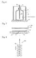
- the sterilizer in accordance with the present invention is provided with a gas introduction means 9 as shown in Fig.4, and a gas mixture containing, for example, 50% or more argon gas is supplied at a rate of 10 liter/min or less from the gas introduction means 9, and is sprayed in the radial direction through a spray member 10 inserted in the upper part of the packaging container 4.
- the gases are preferred to be cooled to a suitable temperature for the supply.
- the discharge side electrode 5 is inserted in the packaging container 4 as shown in Fig.1, to carry out the sterilization process by applying the high voltage pulses thereto.
- An insertion amount of the discharge side electrode 5 into the packaging container 4 is not less than 1/10 of the packaging container 4 in height dimension, preferably, about 9/10.
- the insertion amount of the discharge side electrode 5 is less than 1/10, a discharge amount into the packaging container 4 becomes insufficient, and when the insertion amount of the discharge side electrode 5 exceeds 9/10 in height, the bottom of the packaging container 4 is in danger of thermal deformation.
- a voltage of 38 to 80kV with a frequency of 100 to 3000pps is applied, and duration of the high voltage pulse discharges is specified to be 10sec, for example, in a case of a 500ml plastic container as the packaging container 4.
- the discharge side electrode 5 is formed with helical uneven parts 5a on the outer peripheral surface as described above, the strong high voltage pulse discharges are effectively generated from the tops of the helically continuous projections, and also the high voltage pulse discharges are radially expanded almost over the whole area at 360 degrees centering the discharge side electrode 5.
- the sterilization efficiency of the packaging container 4 is substantially improved and also the high voltage pulses are uniformly discharged to the packaging container 4, unevenness of the sterilization can be prevented, and moreover, the packaging container 4 is also prevented from partial thermal deformation.
- the second embodiment in accordance with the present invention is similar to the first embodiment of the present invention except that a conventional round bar electrode is used as the discharge side electrode 5, and that as shown in Fig.3, the sterilizer A1 of the present invention is provided with a liquid supply means 7 for giving water or an aqueous solution to the internal surface of the packaging container 4 before discharge.
- the packaging container 4 is housed in the treating vessel 1, and the process of giving water or an aqueous solution onto the internal surface of this packaging container is carried out.
- This water-giving process is performed by the liquid supply means 7 and the spraying member 8 for giving water or an aqueous solution.
- the spray member 8 a spray, a nebulizer, or the like can be used.
- the water to be given into the packaging container 4 for example, pure water not containing impurities is suitable, and as to the aqueous solution, an organic aqueous solution containing ethanol, acetone, or the like and an inorganic aqueous solution containing electrolytes can be used.
- the water or the aqueous solution is fed by pressure from the liquid supply means 7, and is sprayed in the radial directions by the spray member 8 inserted in the upper part of the packaging container, and water particles are made to almost uniformly adhere to over the internal surface of the packaging container 4.
- the particle is a few ⁇ m in diameter, and in the case of a packaging container 4 such as a plastic container having a capacity of about 500ml, an amount of the pure water supply is set to 0.01g to 10g. In a case of a pure water supply amount exceeding 10g, the high voltage pulse discharges to be performed later become hard to be generated, and in a case of an amount less than 0.01 g, uniform adhesion of pure water becomes impossible.
- the state in which the pure water particles cloud the whole internal surface of the packaging container 4 shows that the water supply and the amount are proper and are under a favorable condition, and for example, in a case of a transparent packaging container or the like, it is possible to visually observe the state in which the whole internal surface is clouded.
- the discharge side electrode 5 is inserted in the packaging container 4, and the sterilization process is carried out by applying the high voltage pulses thereto under the same conditions as described in the first embodiment of the present invention.
- the water particles adhere to the whole internal surface area of the packaging container 4, therefore, the internal surface is uniformly sterilized without uneven plasma generated by the high voltage pulse discharges.
- the third embodiment according to the present invention is similar to the first and second embodiments of the present invention except that the first and second embodiments are combined;
- the sterilizer A1 of the present invention is provided with a gas introduction means 9 and a liquid supply means 7; water or an aqueous solution is fed by pressure from the liquid supply means 7 and is radially sprayed by a spray member 8 inserted in the upper part of the packaging container 4, so that water particles are made to adhere almost uniformly over the internal surface of the packaging container 4; thereafter, a gas mixture containing, for example, 50% or more argon gas is supplied from the gas introduction means 9 at a rate of 10 liters/min or less and sprayed in the radial directions by the spray member 10 inserted in the upper part of the packaging container 4, to purge superfluous moisture floating in the packaging container 4; the discharge side electrode 5 is inserted in the packaging container 4 as shown in Fig.6; and thus the sterilization process is carried out by applying the high voltage pulses thereto under almost the same conditions as described in the first embodiment
- the moisture is removed by detecting it by an unshown sensor, energizing a heater 12 installed on the upper part of the discharge side electrode 5 as shown in Fig.6, and properly heating the discharge side electrode to vaporize the moisture on the surface.
- the sterilization effect is improved in the plasma generated by the high voltage pulse discharges, and moreover, since gas is introduced into the packaging container, the breakdown voltage can be lowered, and the sterilization efficiency of the packaging container is substantially improved in the plasma generated by the high voltage pulse discharges.
- the fourth embodiment of the present invention is similar to the first, second, and third embodiments of the present invention except that the water-giving process and the process for blowing gas are not performed into dividually but performed simultaneously.
- moisture and gas are supplied at the same time by feeding a gas from the gas introduction means 9 into the liquid supply means 7 to humidify it by bubbling herein, and then supplying the gas into the packaging container 4 to be treated.
- the supply of the moisture and the gas by the bubbling is performed at the same time before and during discharge.
- the adhesion of water to the internal surface of the packaging container 4 to be treated and the substitution with the air in the packaging container are performed.
- a gas feeding amount before discharge is controlled so as to be more than that during discharge.
- the gas introduction means 9 is arranged so as to be variable in capability.
- the discharge side electrode is placed outside of the packaging container 4 to be treated, and during discharge, it is placed inside of the packaging container 4 to be treated.
- a gas substitution rate in the packaging container 4 to be treated is increased, and also water is made to adhere to the internal surface of this packaging container while water is prevented from adhering to the discharge side electrode, and during discharge, a gas feeding amount is decreased to replenish the packaging container 4 for treatment with the gas and generate discharges with efficiency, and also the adhesion of water to the discharge side electrode in the packaging container for treatment is suppressed.
- water is given to the internal surface of the packaging container 4 and a gas is introduced into the packaging container 4, therefore, just as the case of the third embodiment of the present invention, a sterilization efficiency of the packaging container is substantially improved, and also the high voltage pulses are uniformly discharged to the packaging container 4, and thus, unevenness of the sterilization is prevented.
- the fifth embodiment of the present invention is similar to the first, second, third, and fourth embodiments of the present invention except that a film is used as a packaging material 4.
- Fig.7 is an explanatory cross section view showing an example of the embodiment applying the present invention to the sterilization of a film.
- the sterilizer A2 comprises an unshown pulse power source for generating a high pulse voltage, a discharge side electrode 5 provided with unevenness (helical unevenness) having continuous projections to be applied with the high pulse voltage generated by the pulse power source, a packaging material (film) 4 for a treatment of sterilization by the high voltage pulses, an insulating plate 11 formed of a dielectric such as acrylic resin, ceramics, polycarbonate, polyvinyl chloride placed under the packaging material 4, and a ground side electrode 2 placed under the insulating plate 11 so as to be opposed to the discharge side of the discharge side electrode 5.
- a dielectric such as acrylic resin, ceramics, polycarbonate, polyvinyl chloride
- the ground side electrode 2 is formed of a metal such as stainless steel a little wider than the width of the packaging material 4.
- the ground side electrode 2 is provided with an unshown terminal for ground line connection.
- the discharge side electrode 5 may be provided with a plurality of terminals.
- the top surface (the surface to be in contact with packaging goods) of the packaging material 4 is treated by sterilization under almost the same conditions described in the first embodiment of the present invention, by placing the packaging material 4 subjected to sterilization between both electrodes under normal temperature and normal pressure, and generating plasma by applying the high voltage pulses from an unshown high voltage pulse power source while moving the packaging material 4 by a moving means in the gas atmosphere.
- the sterilization treatment of the packaging material 4 under almost the same conditions as described in the first embodiment according to the present invention by feeding water or an aqueous solution by pressure from an unshown liquid supply means; spraying it over the top surface of the packaging material 4; letting water particles almost uniformly adhere to all over the top surface of the packaging material 4; placing between both electrodes the packaging material 4, which is given water particles and is subjected to sterilization, under normal temperature and normal pressure; and generating plasma by applying the high voltage pulses from the unshown high voltage pulse power source while moving the packaging material 4 in a gas atmosphere by the moving means, is able to make an improvement on the sterilization effect, therefore, this sterilization treatment is preferable.
- the use of the treating vessel 1 is mentioned as an example, however, it is not always necessary to use the treating vessel 1.
- the forms of the treating vessel 1 and the ground side electrode 2 are not particularly limited, but they may be polygonal, or similar figure to the packaging material to be treated.
- a predetermined quantity of spores of Bucillus subtilis, B. cereus, or Asperillus niger are made to uniformly adhere to the internal surface of a 500ml plastic container, and this is adopted as a bacteria adhesion packaging container for testing sterilization.
- the above bacteria adhesion packaging container for sterilization test is placed at a predetermined position of the sterilizer in accordance with the present invention as illustrated in Fig.1, and high voltage pulses were applied thereto.
- the discharge side electrode used is a disc type electrode made of SUS (having a 15mm disc diameter, and a 30mm pitch of discs) as illustrated in Fig.8, and the discharge conditions are 45kV, 400Hz, and 10 seconds.
- the disc type electrode 5A shown in Fig.8 is provided with a plurality of discs 13 arranged in parallel at a pitch p.
- a nitrogen gas was introduced into the bacteria adhesion packaging container, and purged the container of the impurities which might be remaining therein (5l/min, 30seconds). Thereafter, a tripto-soya-bouillon culture medium of 30ml was poured into the container immediately, and was fully shaken with a sterilized cap on the container before incubating the bacteria under the following conditions.
- the results of the sterilization effect value D are shown in Table 1 together with a water adhesion amount, an adhesion method, a discharge side electrode used, a kind of gas introduced, a gas flow rate, or the like.
- the test was carried out in the same way as in the Embodiment 1 except that using the sterilizer shown in Fig.3, water was sprayed (3g/container) in the container before the electrical discharge, and a 10mm diameter round bar electrode of stainless steel (SUS) was used as the discharge side electrode, and the results are shown in the Table 1.
- the sterilization method as claimed in claim 1 of the present invention comprising a power source for generating high voltage, a discharge side electrode to which the high voltage generated by the power source is applied, and a ground side electrode placed so as to be opposed to the discharge side of the discharge side electrode; in which a packaging material to be sterilized is placed between both electrodes under normal temperature and normal pressure, and is sterilized by applying the high voltage pulses in a gas atmosphere, the discharge side electrode is provided with unevenness having continuous projections on the discharge side surface, therefore, the method has a remarkable effect that strong high voltage pulse discharges are not generated from the tip of the discharge side electrode, but can be generated uniformly from the tops of the uneven parts on the outer peripheral surface.
- the method is able to improve the sterilization effect of the packaging materials for packaging articles to be packed such as liquids, solids, or a combination of both which are foods, medical supplies, Chinese medicines, cosmetics, feeds, fertilizer, or the like, especially packaging materials for packaging foods.
- the sterilization method as claimed in claim 1 has another remarkable effect that since the discharge side electrode is provided with helical unevenness on the outer peripheral surface, the strong high voltage pulse discharges are not generated from the tip of the discharge side electrode, but can be generated uniformly from the tops of the helical projections centering the discharge side electrode, and thus, the method is able to improve the sterilization effect and prevent non-uniformity of the sterilization.
- the packaging material is a container or a film in the sterilization method as claimed in claim 1 or 2. Therefore, the method has another remarkable effect of being able to sterilize not only containers such as pet bottles and cups, but also plane films by the high voltage pulses.
- the packaging material is a container and the discharge side electrode is inserted in the container in the sterilization method as claimed in any of claims 1 to 3. Therefore, the method has another remarkable effect of being able to uniformly and efficiently sterilize the internal surface of the container without unevenness by generating the high voltage pulse discharges.
- the gas is at least one kind of gas to be selected from a group of oxygen, nitrogen, hydrogen, carbon dioxide, air, argon, and helium, in the sterilization method as claimed in any of claims 1 to 4. Therefore, the method has further remarkable effects of being able to decrease the breakdown voltage and perform favorable sterilization in the plasma generated by the high voltage pulse discharges.
- the sterilization method claimed as in claim 6 of the present invention at least one kind of gas selected from a group of oxygen, nitrogen, hydrogen, carbon dioxide, air, argon, and helium is introduced during discharge in the method claimed as in any of claims 1 to 5. Therefore, the method has further remarkable effects of being able to make effective use of the gas, also to lower the breakdown voltage, and to perform favorable sterilization in the plasma generated by the high voltage pulse discharges.
- the sterilization method claimed as in claim 7 of the present invention water or an aqueous solution is given to the packaging material before discharge, during discharge, or before and during discharge to produce active oxygen in the method in which the sterilizer is provided with a power source for generating high voltage, a discharge side electrode to which the high voltage generated by the power source is applied, and a ground side electrode placed so as to be opposed to the discharge side of the discharge side electrode; in which a packaging material to be sterilized is placed between both electrodes under normal temperature and normal pressure, and is sterilized by applying the high voltage pulses in a gas atmosphere, therefore, the method has another remarkable effect of being able to improve the sterilization effect of the packaging material for packaging articles to be packaged as liquids, solids, and a combination thereof such as foods, medical supplies, Chinese medicines, cosmetics, feeds, and fertilizers, especially packaging materials for packaging foods.
- the water or aqueous solution is given so as to cloud the surface of the packaging material in the sterilization method as claimed in claim 7. Therefore, the method has further remarkable effects of being able to improve the sterilization effect by letting particles of, for example, pure water or aqueous solution adhere to the surface of the packaging material so that, for example, the surface of a packaging material formed of a transparent material is clouded, and applying the high voltage pulses thereto in this state, and also being able to uniformly sterilize the surface of the packaging material with efficiency without unevenness.
- the gas is at least one kind of gas selected from a group of oxygen, nitrogen, hydrogen, carbon dioxide, air, argon, and helium, and the gas is humidified with the water or aqueous solution and introduced before discharge, during discharge, or before and during discharge. Therefore; the method has further remarkable effects that the gas can be used effectively; the breakdown voltage can be lowered; favorable sterilization can be performed into the plasma generated by the high voltage pulse discharges; and further, the sterilization effect can be improved by giving the water or aqueous solution to the packaging material.
- the discharge side electrode is provided with unevenness having continuous projections on the discharge side surface. Therefore, the method has another remarkable effect that strong high voltage pulse discharges can be generated uniformly from the tops of the projections and uneven sterilization can be prevented.
- the unevenness on the discharge side surface is formed intoto a helical structure. Therefore, the method has another remarkable effect that strong high voltage pulse discharges are not generated from the tip of the discharge side electrode, but the strong high voltage pulse discharges are uniformly generated from the tops of the helical projections radially centering the discharge side electrode, and thus, the sterilization effect can be improved and uneven sterilization can be eliminated.
- the packaging material is a container of a film. Therefore, the method has another remarkable effect of being able to sterilizing not only containers but also plane films.
- the packaging material is a container and the discharge side electrode is inserted in the container. Therefore, the method has another effect of being able to uniformly sterilize the internal surface of the container with efficiency without unevenness.
- the sterilizer in the sterilizer which is provided with a power source for generating high voltage, a discharge side electrode to which the high voltage generated by the power source is applied, and a ground side electrode placed so as to be opposed to the discharge side of the discharge side electrode; in which a packaging material to be sterilized is placed between both electrodes under normal temperature and normal pressure, and is sterilized by applying the high voltage pulses in a gas atmosphere, the discharge side electrode is provided with unevenness having continuous projections on the discharge side surface.
- the method has a remarkable effect that strong high voltage pulse discharges are not generated from the tip of the discharge side electrode, but can uniformly be generated from the tops of the uneven parts on the outer peripheral surface, and thus, the method is able to improve the sterilization effect of the packaging materials for packaging articles to be packed such as liquids, solids, or a combination of both which are foods, medical supplies, Chinese medicines, cosmetics, feeds, fertilizer, or the like, especially packaging materials for packaging foods.
- the unevenness on the discharge side electrode surface is arranged in a helical structure. Therefore, the sterilizer has another remarkable effect that strong high voltage pulse discharges are not generated from the tip of the discharge side electrode, but the strong high voltage pulse discharges can he generated from the tops of the helical uneven parts uniformly and radially centering the discharge side electrode, and this improves the sterilization effect and eliminates non-uniformity of sterilization.
- the packaging material placed between the both electrodes is a container or a film. Therefore, the sterilizer has another remarkable effect that not only containers but also plane films can be sterilized by the sterilizer using the high voltage pulses.
- the packaging material is a container
- the sterilizer is provided with the discharge side electrode to be inserted in this container, and the ground side electrode arranged along the outer periphery of the container, and strong high voltage pulse discharges are effectively generated from the outer peripheral surface of the discharge side electrode. Therefore, the sterilizer has another remarkable effect of being able to uniformly sterilize the internal surface of the container with efficiency by inserting the discharge side electrode in the container, and generating the high voltage pulse discharges across the ground side electrode.
- the sterilizer in the sterilizer as claimed in any of claims 14 to 17, the sterilizer is provided with an introduction means for introducing at least one kind of gas selected from a group of oxygen, nitrogen, hydrogen, carbon dioxide, air, argon, and helium during discharge, therefore, the sterilizer has further remarkable effects that the gas can be introduced with ease during discharge by using this introduction means and can be used effectively, and moreover, the breakdown voltage is lowered, and favorable sterilization can be can be carried out in the plasma generated by the high voltage pulse discharges.
- an introduction means for introducing at least one kind of gas selected from a group of oxygen, nitrogen, hydrogen, carbon dioxide, air, argon, and helium during discharge
- the sterilizer which is provided with a power source for generating high voltage, a discharge side electrode to which the high voltage generated by the power source is applied, and a ground side electrode placed so as to be opposed to the discharge side of the discharge side electrode; in which a packaging material to be sterilized is placed between both electrodes under normal temperature and normal pressure, and is sterilized by applying the high voltage pulses in a gas atmosphere, is provided with a liquid supply means for giving water or an aqueous solution to the packaging material before discharge, during discharge, or before and during discharge, therefore, the sterilizer has a remarkable effect that strong high voltage pulse discharges are effectively generated from the outer peripheral surface of the discharge side electrode by giving the water or aqueous solution to the packaging material by this liquid supply means, and thus, the sterilizer is able to improve the sterilization effect of the packaging materials for packaging articles to be packed such as liquids, solids, or a combination of both which are foods, medical supplies, Chinese medicines, cosmetics, feeds, fertilizer
- said liquid supply means gives water or an aqueous solution to the packaging material so as to cloud the surface thereof. Therefore, the sterilizer has further remarkable effects that the sterilization effect can be improved by making, for example, particles of pure water or aqueous solution adhere to the surface of the packaging material by the liquid supply means so that the surface of the packaging material made of, for example, a transparent material is clouded, and applying the high voltage pulses in this state, and also the surface of the packaging material can be sterilized uniformly with efficiency and further; moisture does not remain on the surface of the packaging material after sterilization.
- the sterilizer in the sterilizer as claimed in claim 19 or 20, at least one kind of gas selected from a group of oxygen, nitrogen, hydrogen, carbon dioxide, air, argon, and helium is humidified with said water or aqueous solution and the liquid supply means gives the water or aqueous solution to the packaging material before discharge, during discharge, or before and during discharge. Therefore, the sterilizer has further remarkable effects that the gas can effectively be used; the breakdown voltage can be lowered; favorable sterilization can be carried out in the plasma generated by the high voltage pulse discharges; and the sterilization effect can be improved by giving the water or aqueous solution to the packaging material.
- a group of oxygen, nitrogen, hydrogen, carbon dioxide, air, argon, and helium is humidified with said water or aqueous solution and the liquid supply means gives the water or aqueous solution to the packaging material before discharge, during discharge, or before and during discharge. Therefore, the sterilizer has further remarkable effects that the gas can effectively be used; the breakdown voltage can be lowered; favorable sterilization can be carried out in
- the discharge side electrode is provided with unevenness having continuous projections on the discharge side surface. Therefore, the sterilizer has another remarkable effect of being able to generate uniform strong high voltage pulse discharges from the tops of the projections on the outer peripheral surface, and thereby improving the sterilization effect.
- the unevenness on the discharge side surface is arranged in a helical structure and strong high voltage pulse discharges are not generated from the tip of the discharge side electrode, but the discharge side electrode has unevenness of a helical structure on the outer peripheral surface Therefore, the sterilizer has further remarkable effects of being able to generate the strong high voltage pulse discharges from the tops of the projections of said helical structure radially and uniformly centering the discharge side electrode, and improve the sterilization effect and eliminate non-uniformity of sterilization.
- the packaging material placed between both electrodes is a container or a film. Therefore, the sterilizer has another remarkable effect of being able to sterilize not only containers, and also plane films.
- said packaging material is a container
- the sterilizer is provided with a discharge side electrode to be inserted in this container, and a ground side electrode arranged along the outer peripheral surface of the container, so strong high voltage pulse discharges are effectively generated from the outer peripheral surface of the discharge side electrode. Therefore, the sterilizer has another remarkable effect of being able to uniformly sterilize the internal surface of the container with efficiency by inserting the discharge side electrode into the container and generating the high voltage pulse discharges across the ground side electrode.
Landscapes
- Engineering & Computer Science (AREA)
- Health & Medical Sciences (AREA)
- Mechanical Engineering (AREA)
- Physics & Mathematics (AREA)
- Plasma & Fusion (AREA)
- Epidemiology (AREA)
- Life Sciences & Earth Sciences (AREA)
- Animal Behavior & Ethology (AREA)
- General Health & Medical Sciences (AREA)
- Public Health (AREA)
- Veterinary Medicine (AREA)
- Apparatus For Disinfection Or Sterilisation (AREA)
Applications Claiming Priority (2)
| Application Number | Priority Date | Filing Date | Title |
|---|---|---|---|
| JP2002181794A JP4599023B2 (ja) | 2002-06-21 | 2002-06-21 | 高電圧パルス電源を用いた包装材料の殺菌方法およびその装置 |
| JP2002181794 | 2002-06-21 |
Publications (2)
| Publication Number | Publication Date |
|---|---|
| EP1375357A1 true EP1375357A1 (de) | 2004-01-02 |
| EP1375357B1 EP1375357B1 (de) | 2008-08-27 |
Family
ID=29717541
Family Applications (1)
| Application Number | Title | Priority Date | Filing Date |
|---|---|---|---|
| EP03013549A Expired - Lifetime EP1375357B1 (de) | 2002-06-21 | 2003-06-13 | Verfahren und Vorrichtung zur Sterilisierung von Verpackungsmaterial mittels Hochspannungsimpulsen |
Country Status (5)
| Country | Link |
|---|---|
| US (1) | US7425300B2 (de) |
| EP (1) | EP1375357B1 (de) |
| JP (1) | JP4599023B2 (de) |
| CN (1) | CN100340455C (de) |
| DE (1) | DE60323183D1 (de) |
Cited By (3)
| Publication number | Priority date | Publication date | Assignee | Title |
|---|---|---|---|---|
| WO2009101156A3 (de) * | 2008-02-13 | 2009-10-29 | The Coca-Cola Company | Verfahren und vorrichtung zur sterilisation von verpackungs- und/oder filtermaterial und/oder behältern, diesbezügliche verwendung von plasma sowie entsprechend behandeltes material oder behälter |
| DE102017123871A1 (de) * | 2017-10-10 | 2019-04-11 | Plasmatreat Gmbh | Verfahren zur Oberflächendesinfektion und zur Desinfektion von Komponenten einer Abfüllanlage |
| EP3363471A4 (de) * | 2015-10-13 | 2019-05-15 | Suntory Holdings Limited | Sterilisationsvorrichtung |
Families Citing this family (19)
| Publication number | Priority date | Publication date | Assignee | Title |
|---|---|---|---|---|
| JP4842626B2 (ja) * | 2004-11-26 | 2011-12-21 | 大日本印刷株式会社 | 殺菌方法および殺菌装置 |
| EP1991993B2 (de) * | 2006-02-14 | 2017-01-25 | Hitachi Zosen Corporation | Elektronenstrahlemitter |
| JP5019155B2 (ja) * | 2006-08-14 | 2012-09-05 | 大日本印刷株式会社 | 殺菌装置および殺菌方法 |
| US8277727B2 (en) * | 2007-01-10 | 2012-10-02 | Jerome Pollak | Device and method for inactivation and/or sterilization using plasma |
| JP5119031B2 (ja) * | 2008-04-15 | 2013-01-16 | 株式会社日立ハイテクノロジーズ | 反応セルの製造方法、及び、反応セルを備えた自動分析装置 |
| GB0906091D0 (en) * | 2009-04-07 | 2009-05-20 | Snowball Malcolm R | None invasive disinfector |
| DE102010044244A1 (de) * | 2010-09-02 | 2012-03-08 | Khs Gmbh | Verfahren sowie Vorrichtung zum Behandeln von Behältern |
| KR101843771B1 (ko) * | 2014-08-18 | 2018-03-30 | 주식회사 플라즈맵 | 플라즈마 살균 필름 및 플라즈마 살균 포장 용기 |
| KR102214927B1 (ko) * | 2014-09-18 | 2021-02-10 | 제넥스 디스인펙션 서비시즈 인코퍼레이티드 | 조절된 파워 플럭스를 갖는 펄스화된 광을 사용하는 룸 및 구역 살균 장치 및 펄스 간의 가시 광 보상을 갖는 광 시스템 |
| JP6674950B2 (ja) * | 2015-06-12 | 2020-04-01 | 株式会社エンビジョンAescエナジーデバイス | 電極の水分量測定方法、リチウムイオン二次電池用電極の製造方法、水分量測定装置および水分量測定方法 |
| US10194672B2 (en) | 2015-10-23 | 2019-02-05 | NanoGuard Technologies, LLC | Reactive gas, reactive gas generation system and product treatment using reactive gas |
| US11357243B2 (en) * | 2016-07-04 | 2022-06-14 | Charles Adriano Duvoisin | System and method for the electromagnetic energizing of packaged content and corresponding device |
| CN107416281B (zh) * | 2017-08-31 | 2019-04-02 | 重庆兴致臻现代农业有限公司 | 一种食用菌包装袋的杀菌方法 |
| US11279634B2 (en) * | 2018-03-14 | 2022-03-22 | Mitsubishi Electric Corporation | Water treatment device and water treatment method |
| IT201800006094A1 (it) * | 2018-06-07 | 2019-12-07 | Metodo di sterilizzazione al plasma | |
| US10925144B2 (en) | 2019-06-14 | 2021-02-16 | NanoGuard Technologies, LLC | Electrode assembly, dielectric barrier discharge system and use thereof |
| US11896731B2 (en) | 2020-04-03 | 2024-02-13 | NanoGuard Technologies, LLC | Methods of disarming viruses using reactive gas |
| CN111765032B (zh) * | 2020-06-12 | 2022-06-14 | 沈阳航空航天大学 | 一种滑动弧等离子体-高扰动交叉结构的燃油雾化喷嘴 |
| KR102317168B1 (ko) * | 2021-02-22 | 2021-10-26 | 주식회사 비이에프 | 전자석을 이용한 고전압 펄스 전기장 발생 장치 및 이를 이용한 식품 살균 및 향미와 향기 첨가 방법 |
Citations (6)
| Publication number | Priority date | Publication date | Assignee | Title |
|---|---|---|---|---|
| GB1098693A (en) * | 1964-01-24 | 1968-01-10 | Little Inc A | Sterilization of surfaces by gaseous plasmas and apparatus therefor |
| US3466850A (en) * | 1966-04-29 | 1969-09-16 | Graham Enock Mfg Co Ltd | Packaging |
| US3701628A (en) * | 1970-02-25 | 1972-10-31 | Little Inc A | Treatment of surface with low-pressure plasmas |
| US5084239A (en) * | 1990-08-31 | 1992-01-28 | Abtox, Inc. | Plasma sterilizing process with pulsed antimicrobial agent treatment |
| US5521351A (en) * | 1994-08-30 | 1996-05-28 | Wisconsin Alumni Research Foundation | Method and apparatus for plasma surface treatment of the interior of hollow forms |
| WO1998051608A1 (fr) * | 1997-05-12 | 1998-11-19 | Ist Instant Surface Technology S.A. | Procede et dispositif pour traitement de surface |
Family Cites Families (10)
| Publication number | Priority date | Publication date | Assignee | Title |
|---|---|---|---|---|
| US3383163A (en) * | 1964-01-24 | 1968-05-14 | Little Inc A | Treatment of surfaces |
| US3819985A (en) * | 1972-12-01 | 1974-06-25 | R Dusevoir | Discharge electrodes for electrostatic precipitators and method of shipment and installation |
| DE3414268A1 (de) * | 1984-04-14 | 1985-10-24 | Kolbus Gmbh & Co Kg | Verfahren und vorrichtung zum entkeimen von lebensmittelbehaeltern |
| JP3635114B2 (ja) * | 1994-12-19 | 2005-04-06 | 藤森工業株式会社 | 殺菌方法 |
| JPH0999922A (ja) * | 1995-10-03 | 1997-04-15 | Ishikawajima Harima Heavy Ind Co Ltd | 食品容器の殺菌方法及びその装置 |
| JPH09108313A (ja) * | 1995-10-24 | 1997-04-28 | Mitsubishi Electric Corp | 微生物繁殖防止方法およびその装置 |
| RU2067003C1 (ru) * | 1995-12-15 | 1996-09-27 | Общество с ограниченной ответственностью Научно-производственная фирма "Плайн" | Способ обработки поверхностей тел и устройство для его осуществления |
| JP2001069959A (ja) * | 1999-09-02 | 2001-03-21 | Sanyo Electric Co Ltd | 種子及び香辛料等の殺菌処理方法 |
| FR2814079B1 (fr) * | 2000-09-15 | 2005-05-13 | Absys | Systeme de sterilisation par plasma |
| US6441554B1 (en) * | 2000-11-28 | 2002-08-27 | Se Plasma Inc. | Apparatus for generating low temperature plasma at atmospheric pressure |
-
2002
- 2002-06-21 JP JP2002181794A patent/JP4599023B2/ja not_active Expired - Fee Related
-
2003
- 2003-06-13 EP EP03013549A patent/EP1375357B1/de not_active Expired - Lifetime
- 2003-06-13 DE DE60323183T patent/DE60323183D1/de not_active Expired - Lifetime
- 2003-06-20 US US10/601,007 patent/US7425300B2/en not_active Expired - Fee Related
- 2003-06-23 CN CNB031486339A patent/CN100340455C/zh not_active Expired - Fee Related
Patent Citations (6)
| Publication number | Priority date | Publication date | Assignee | Title |
|---|---|---|---|---|
| GB1098693A (en) * | 1964-01-24 | 1968-01-10 | Little Inc A | Sterilization of surfaces by gaseous plasmas and apparatus therefor |
| US3466850A (en) * | 1966-04-29 | 1969-09-16 | Graham Enock Mfg Co Ltd | Packaging |
| US3701628A (en) * | 1970-02-25 | 1972-10-31 | Little Inc A | Treatment of surface with low-pressure plasmas |
| US5084239A (en) * | 1990-08-31 | 1992-01-28 | Abtox, Inc. | Plasma sterilizing process with pulsed antimicrobial agent treatment |
| US5521351A (en) * | 1994-08-30 | 1996-05-28 | Wisconsin Alumni Research Foundation | Method and apparatus for plasma surface treatment of the interior of hollow forms |
| WO1998051608A1 (fr) * | 1997-05-12 | 1998-11-19 | Ist Instant Surface Technology S.A. | Procede et dispositif pour traitement de surface |
Cited By (3)
| Publication number | Priority date | Publication date | Assignee | Title |
|---|---|---|---|---|
| WO2009101156A3 (de) * | 2008-02-13 | 2009-10-29 | The Coca-Cola Company | Verfahren und vorrichtung zur sterilisation von verpackungs- und/oder filtermaterial und/oder behältern, diesbezügliche verwendung von plasma sowie entsprechend behandeltes material oder behälter |
| EP3363471A4 (de) * | 2015-10-13 | 2019-05-15 | Suntory Holdings Limited | Sterilisationsvorrichtung |
| DE102017123871A1 (de) * | 2017-10-10 | 2019-04-11 | Plasmatreat Gmbh | Verfahren zur Oberflächendesinfektion und zur Desinfektion von Komponenten einer Abfüllanlage |
Also Published As
| Publication number | Publication date |
|---|---|
| US20040047762A1 (en) | 2004-03-11 |
| CN1491863A (zh) | 2004-04-28 |
| US7425300B2 (en) | 2008-09-16 |
| JP4599023B2 (ja) | 2010-12-15 |
| JP2004026171A (ja) | 2004-01-29 |
| EP1375357B1 (de) | 2008-08-27 |
| DE60323183D1 (de) | 2008-10-09 |
| CN100340455C (zh) | 2007-10-03 |
Similar Documents
| Publication | Publication Date | Title |
|---|---|---|
| US7425300B2 (en) | Method for sterilizing packaging material by using high voltage pulse power source | |
| CN1795016A (zh) | 真空灭菌工艺和装置 | |
| JP6704448B2 (ja) | 殺菌装置 | |
| US6497839B1 (en) | Sterilizer and sterilization method utilizing high voltage | |
| JP2001054556A (ja) | 大気圧低温プラズマ殺菌方法 | |
| JP2020010694A (ja) | 大気圧プラズマ殺菌処理装置 | |
| JP4841236B2 (ja) | 殺菌方法および殺菌装置 | |
| JP4842626B2 (ja) | 殺菌方法および殺菌装置 | |
| JPWO2002001971A1 (ja) | 高電圧を利用した殺菌装置およびそれを用いた穀類及び種子等の殺菌対象物の殺菌方法 | |
| JP5019155B2 (ja) | 殺菌装置および殺菌方法 | |
| JP3888715B2 (ja) | 滅菌装置及び滅菌方法 | |
| JP2007269325A (ja) | 殺菌装置および殺菌方法 | |
| EP3363471B1 (de) | Sterilisationsvorrichtung und verfahren mit dieser | |
| EP0873144A1 (de) | Verfahren und vorrichtung zur behandlung von oberflächen | |
| JP2005278809A (ja) | 高電圧を利用した殺菌装置 | |
| JP2004248989A (ja) | プラズマ滅菌装置 | |
| JP2004359307A (ja) | 容器の殺菌方法及び装置、並びにそれらに用いる殺菌用の処理槽 | |
| JP2006331763A (ja) | プラズマ処理装置及びそれを用いたプラズマ処理方法 | |
| KR20230025826A (ko) | 저온 플라즈마를 사용한 분말 살균시스템 | |
| CN209790442U (zh) | 一种新型单喷嘴-板-筒式高压脉冲等离子体灭菌反应器 | |
| WO2022064866A1 (ja) | 連続除染装置 | |
| JP6857004B2 (ja) | 殺菌方法 | |
| JP6820714B2 (ja) | 殺菌装置 | |
| EP3363472B1 (de) | Sterilisationsverfahren mittels plasmaserzeugten reaktiven sauerstoffs | |
| JP2003062047A (ja) | 容器の殺菌方法及び装置 |
Legal Events
| Date | Code | Title | Description |
|---|---|---|---|
| PUAI | Public reference made under article 153(3) epc to a published international application that has entered the european phase |
Free format text: ORIGINAL CODE: 0009012 |
|
| AK | Designated contracting states |
Kind code of ref document: A1 Designated state(s): AT BE BG CH CY CZ DE DK EE ES FI FR GB GR HU IE IT LI LU MC NL PT RO SE SI SK TR |
|
| AX | Request for extension of the european patent |
Extension state: AL LT LV MK |
|
| 17P | Request for examination filed |
Effective date: 20040218 |
|
| AKX | Designation fees paid |
Designated state(s): BE DE FR GB IT |
|
| 17Q | First examination report despatched |
Effective date: 20060920 |
|
| 17Q | First examination report despatched |
Effective date: 20060920 |
|
| GRAP | Despatch of communication of intention to grant a patent |
Free format text: ORIGINAL CODE: EPIDOSNIGR1 |
|
| GRAS | Grant fee paid |
Free format text: ORIGINAL CODE: EPIDOSNIGR3 |
|
| GRAA | (expected) grant |
Free format text: ORIGINAL CODE: 0009210 |
|
| AK | Designated contracting states |
Kind code of ref document: B1 Designated state(s): BE DE FR GB IT |
|
| REG | Reference to a national code |
Ref country code: GB Ref legal event code: FG4D |
|
| REF | Corresponds to: |
Ref document number: 60323183 Country of ref document: DE Date of ref document: 20081009 Kind code of ref document: P |
|
| PLBE | No opposition filed within time limit |
Free format text: ORIGINAL CODE: 0009261 |
|
| STAA | Information on the status of an ep patent application or granted ep patent |
Free format text: STATUS: NO OPPOSITION FILED WITHIN TIME LIMIT |
|
| 26N | No opposition filed |
Effective date: 20090528 |
|
| PGFP | Annual fee paid to national office [announced via postgrant information from national office to epo] |
Ref country code: DE Payment date: 20120516 Year of fee payment: 10 |
|
| PGFP | Annual fee paid to national office [announced via postgrant information from national office to epo] |
Ref country code: FR Payment date: 20120705 Year of fee payment: 10 Ref country code: GB Payment date: 20120621 Year of fee payment: 10 |
|
| PGFP | Annual fee paid to national office [announced via postgrant information from national office to epo] |
Ref country code: IT Payment date: 20120623 Year of fee payment: 10 |
|
| PGFP | Annual fee paid to national office [announced via postgrant information from national office to epo] |
Ref country code: BE Payment date: 20120622 Year of fee payment: 10 |
|
| BERE | Be: lapsed |
Owner name: DAI NIPPON PRINTING CO., LTD. Effective date: 20130630 Owner name: SANYO ELECTRIC CO. LTD Effective date: 20130630 |
|
| GBPC | Gb: european patent ceased through non-payment of renewal fee |
Effective date: 20130613 |
|
| REG | Reference to a national code |
Ref country code: FR Ref legal event code: ST Effective date: 20140228 |
|
| PG25 | Lapsed in a contracting state [announced via postgrant information from national office to epo] |
Ref country code: BE Free format text: LAPSE BECAUSE OF NON-PAYMENT OF DUE FEES Effective date: 20130630 |
|
| REG | Reference to a national code |
Ref country code: DE Ref legal event code: R119 Ref document number: 60323183 Country of ref document: DE Effective date: 20140101 |
|
| PG25 | Lapsed in a contracting state [announced via postgrant information from national office to epo] |
Ref country code: DE Free format text: LAPSE BECAUSE OF NON-PAYMENT OF DUE FEES Effective date: 20140101 Ref country code: GB Free format text: LAPSE BECAUSE OF NON-PAYMENT OF DUE FEES Effective date: 20130613 |
|
| PG25 | Lapsed in a contracting state [announced via postgrant information from national office to epo] |
Ref country code: IT Free format text: LAPSE BECAUSE OF NON-PAYMENT OF DUE FEES Effective date: 20130613 Ref country code: FR Free format text: LAPSE BECAUSE OF NON-PAYMENT OF DUE FEES Effective date: 20130701 |