EP1375397B1 - Dispositif et procédé pour manipuler des éléments de construction en forme de plaques - Google Patents
Dispositif et procédé pour manipuler des éléments de construction en forme de plaques Download PDFInfo
- Publication number
- EP1375397B1 EP1375397B1 EP03077046A EP03077046A EP1375397B1 EP 1375397 B1 EP1375397 B1 EP 1375397B1 EP 03077046 A EP03077046 A EP 03077046A EP 03077046 A EP03077046 A EP 03077046A EP 1375397 B1 EP1375397 B1 EP 1375397B1
- Authority
- EP
- European Patent Office
- Prior art keywords
- cams
- support
- construction elements
- stack
- construction
- Prior art date
- Legal status (The legal status is an assumption and is not a legal conclusion. Google has not performed a legal analysis and makes no representation as to the accuracy of the status listed.)
- Expired - Lifetime
Links
- 238000010276 construction Methods 0.000 title claims abstract description 87
- 238000000034 method Methods 0.000 title claims abstract description 9
- 238000012384 transportation and delivery Methods 0.000 claims abstract description 59
- 230000008878 coupling Effects 0.000 claims abstract description 3
- 238000010168 coupling process Methods 0.000 claims abstract description 3
- 238000005859 coupling reaction Methods 0.000 claims abstract description 3
- 238000004804 winding Methods 0.000 claims description 8
- 230000005484 gravity Effects 0.000 claims description 4
- 239000002184 metal Substances 0.000 claims description 3
- 125000006850 spacer group Chemical group 0.000 claims description 2
- 101100491335 Caenorhabditis elegans mat-2 gene Proteins 0.000 description 15
- 230000002787 reinforcement Effects 0.000 description 12
- 239000000725 suspension Substances 0.000 description 10
- 230000000284 resting effect Effects 0.000 description 3
- 230000000712 assembly Effects 0.000 description 2
- 238000000429 assembly Methods 0.000 description 2
- 239000011449 brick Substances 0.000 description 2
- 230000005540 biological transmission Effects 0.000 description 1
- 230000003247 decreasing effect Effects 0.000 description 1
- 230000000694 effects Effects 0.000 description 1
- 238000002955 isolation Methods 0.000 description 1
- 230000003014 reinforcing effect Effects 0.000 description 1
- 230000001360 synchronised effect Effects 0.000 description 1
Images


Classifications
-
- B—PERFORMING OPERATIONS; TRANSPORTING
- B65—CONVEYING; PACKING; STORING; HANDLING THIN OR FILAMENTARY MATERIAL
- B65G—TRANSPORT OR STORAGE DEVICES, e.g. CONVEYORS FOR LOADING OR TIPPING, SHOP CONVEYOR SYSTEMS OR PNEUMATIC TUBE CONVEYORS
- B65G61/00—Use of pick-up or transfer devices or of manipulators for stacking or de-stacking articles not otherwise provided for
-
- B—PERFORMING OPERATIONS; TRANSPORTING
- B65—CONVEYING; PACKING; STORING; HANDLING THIN OR FILAMENTARY MATERIAL
- B65G—TRANSPORT OR STORAGE DEVICES, e.g. CONVEYORS FOR LOADING OR TIPPING, SHOP CONVEYOR SYSTEMS OR PNEUMATIC TUBE CONVEYORS
- B65G47/00—Article or material-handling devices associated with conveyors; Methods employing such devices
- B65G47/74—Feeding, transfer, or discharging devices of particular kinds or types
- B65G47/90—Devices for picking-up and depositing articles or materials
-
- B—PERFORMING OPERATIONS; TRANSPORTING
- B65—CONVEYING; PACKING; STORING; HANDLING THIN OR FILAMENTARY MATERIAL
- B65G—TRANSPORT OR STORAGE DEVICES, e.g. CONVEYORS FOR LOADING OR TIPPING, SHOP CONVEYOR SYSTEMS OR PNEUMATIC TUBE CONVEYORS
- B65G59/00—De-stacking of articles
- B65G59/06—De-stacking from the bottom of the stack
- B65G59/061—De-stacking from the bottom of the stack articles being separated substantially along the axis of the stack
- B65G59/066—De-stacking from the bottom of the stack articles being separated substantially along the axis of the stack by means of rotary devices or endless elements
-
- B—PERFORMING OPERATIONS; TRANSPORTING
- B66—HOISTING; LIFTING; HAULING
- B66C—CRANES; LOAD-ENGAGING ELEMENTS OR DEVICES FOR CRANES, CAPSTANS, WINCHES, OR TACKLES
- B66C1/00—Load-engaging elements or devices attached to lifting or lowering gear of cranes or adapted for connection therewith for transmitting lifting forces to articles or groups of articles
- B66C1/10—Load-engaging elements or devices attached to lifting or lowering gear of cranes or adapted for connection therewith for transmitting lifting forces to articles or groups of articles by mechanical means
- B66C1/22—Rigid members, e.g. L-shaped members, with parts engaging the under surface of the loads; Crane hooks
- B66C1/28—Duplicate, e.g. pivoted, members engaging the loads from two sides
-
- B—PERFORMING OPERATIONS; TRANSPORTING
- B66—HOISTING; LIFTING; HAULING
- B66C—CRANES; LOAD-ENGAGING ELEMENTS OR DEVICES FOR CRANES, CAPSTANS, WINCHES, OR TACKLES
- B66C1/00—Load-engaging elements or devices attached to lifting or lowering gear of cranes or adapted for connection therewith for transmitting lifting forces to articles or groups of articles
- B66C1/10—Load-engaging elements or devices attached to lifting or lowering gear of cranes or adapted for connection therewith for transmitting lifting forces to articles or groups of articles by mechanical means
- B66C1/62—Load-engaging elements or devices attached to lifting or lowering gear of cranes or adapted for connection therewith for transmitting lifting forces to articles or groups of articles by mechanical means comprising article-engaging members of a shape complementary to that of the articles to be handled
-
- E—FIXED CONSTRUCTIONS
- E04—BUILDING
- E04G—SCAFFOLDING; FORMS; SHUTTERING; BUILDING IMPLEMENTS OR AIDS, OR THEIR USE; HANDLING BUILDING MATERIALS ON THE SITE; REPAIRING, BREAKING-UP OR OTHER WORK ON EXISTING BUILDINGS
- E04G21/00—Preparing, conveying, or working-up building materials or building elements in situ; Other devices or measures for constructional work
- E04G21/14—Conveying or assembling building elements
- E04G21/16—Tools or apparatus
- E04G21/169—Tools or apparatus specially adapted for working-up reinforcement mats
Definitions
- the invention relates to an apparatus for manipulating substantially plate-shaped construction elements.
- DE 27 30 626 discloses an apparatus, comprising a frame which is equipped with clamping means which can be brought into a clamping position around the circumferential edge of a layer of pavement bricks. This layer can then be picked up and transported to a position of use, where it can be released at a desired location. In this way, layers of bricks can be handled, one at the time, without substantial effort or manpower.
- the invention contemplates an apparatus for manipulating substantially plate-shaped construction elements, in which disadvantages of the known apparatuses are avoided while retaining the advantages thereof.
- an apparatus according to the invention is characterized by the measures according to claim 1.
- An apparatus enables a plurality of construction elements to be moved simultaneously to a desired location and to be delivered there one by one. In this manner, manpower can be saved and, moreover, the elements can be positioned fast, safely and accurately.
- a suitable cooperation between the support means and the delivery means each time allows a lowermost element of the stack to be isolated, so that this element is only supported by the delivery means.
- the isolated element can then be manipulated, in particular be released, without this having any effect on the remaining stack.
- the support and delivery means can each be provided with, for instance, two sets of cams, which cams are located above each other, which sets are each movable between a first, supporting position, in which the cams of the sets extend under the lowermost element and, for instance, the second lowermost element of the stack respectively, and a second, non-supporting position.
- the cams of the delivery and support means can, for instance, be driven by hydraulic drive means and are preferably remote-controllable, which promotes the safety of the apparatus. Each cam can then be driven separately, or the cams can be driven collectively, for instance per set, by a single drive means via transmission means suitable for this purpose. Collective driving can contribute to a simpler construction and control.
- At least a part of the moving order of the sets of first and second cams can be coupled, either mechanically or via control logic.
- control of the apparatus can be further simplified and, in addition, security measures can be built in, so that, for instance, the upper cams can only be moved to a non-supporting position if the lower cams are in a supporting position. This prevents the possibility of the entire stack of elements falling down all at once due to incorrect operation of the drive means and thus secures the safety of the apparatus even better.
- provisions can be made to be able to switch off such security settings, when such a delivery of a complete stack is desired, for instance when the apparatus is used to move the plate-shaped construction elements to an intermediate or storage location.
- an apparatus according to the invention is characterized by the measures according to claim 9.
- a taking-up function can, for instance, be achieved by designing the delivery and support means, in particular the sets of first and second cams thereof, such that their mutual positions are interchangeable viewed in vertical direction, for instance by means of lifting means.
- an element can be taken up from a base by moving a then lower set of cams under this element, after which the upper cams can be moved from a supporting position to a non-supporting position, while a stack located on these cams comes to rest on the element just taken up, after which these upper cams can be moved downwards by means of the lifting means under the other cams or at least under the then lowermost construction element, after which the next construction element can be taken up from a base, in the manner described hereinabove.
- an apparatus according to the invention is characterized by the measures according to claim 11.
- the delivery and support means are formed by a number of substantially vertically arranged screw spindles, where the construction elements are directly, or by intervention of suitable adaptor means, taken up between windings, preferably two successive windings, and can be transported upwards or downwards by synchronous rotation of the screw spindles, while the lowermost winding, at least adaptor, can take up or deliver an element.
- an apparatus according to the invention is particularly suitable for manipulating reinforcement mats manufactured, for instance welded, from wire.
- the support and delivery means can extend through meshes formed between the wires, or under the wires.
- an apparatus according to the invention is characterized by the measures according to claim 14.
- Suitable spacers can help to correctly position the support and delivery means within the meshes of the stack of reinforcement mats, that is, at a right distance from the surrounding wires, so that support and delivery means can adequately support these wires in a first position, are clear therefrom in a second position and further have sufficient freedom of movement to be able to move unhindered between the first and second position. In this manner, a proper and safe working of the apparatus can be guaranteed, in which the elements can, on the one hand, be adequately supported and cannot fall down unintentionally and can, on the other hand, be released without a hitch.
- the invention further relates to a method for manipulating substantially plate-shaped elements, characterized by the measures according to claim 17.
- Such a method enables relatively large and heavy construction elements to be manipulated in an efficient, time-saving manner, in which the elements are taken up at a first location, for instance a supply location, one by one or several at a time, are then moved to a second location and are delivered there, one by one or several at a time.
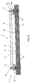
- Figs. 1-3 show a top plan view, front view and side view respectively of an apparatus for manipulating substantially plate-shaped construction elements, in particular reinforcement mats.
- a reinforcement mat is at least understood to be a mat 2 welded from wires, in particular metal longitudinal and cross wires 11, 13, as shown in Fig. 1, which longitudinal and cross wires 11, 13 extend substantially perpendicular to each other and are interconnected at their cross points.
- Such reinforcement or construction mats 2 are frequently used in construction for reinforcing concrete constructions and, depending on their use, can have a considerable size and corresponding weight. This generally makes the mats 2 difficult to manipulate.
- An apparatus 1 improves this, in that it allows a stack of mats 2 to be taken up and moved together to a location of use, where the mats 2 can be delivered one by one.
- the apparatus 1 comprises a frame 3 and four sets of support and delivery devices 10A-D, located near four angular points of the frame 3.
- the frame 3 is built up from two parallel longitudinal beams 4, which are interconnected near their ends by suspension beams 5 and are, at some distance from these ends, connected by at least two cross beams 6.
- the suspension beams 5 project on both sides of the longitudinal beams 4 and, approximately at the height of the cross beams 6, are connected at their projecting ends to the longitudinal beams 4 via inclined support beams 7.
- a rigid, truss-like frame 3 is formed, which acts as a suspension construction for the support and delivery means 10A-D yet to be discussed.
- each suspension beam 5 is provided, near its ends, with an eye 8, which allows the frame 3 to be suspended, in use, from a crane, crab or like means of transport.
- a subframe 15 is suspended, in each of which, two sets of support and delivery means 10A,B and 10C,D are placed.
- the subframes 15 each comprise two box-shaped end parts 12 interconnected by two parallel support beams 14 extending into the end parts 12.
- Each box-shaped end part 12 comprises a pentagonal bottom plate 16, pentagonal cover plate 17 and raised walls 18 extending around these plates 16, 17.
- the cover plates 17 are provided, on an outside, with a bracket 20, by means of which the end parts 12 and consequently the subframes 15 are suspended from the ends of the suspension beam 5, with the subframe 15 extending substantially parallel to the suspension beam 5.
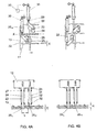
- the support and delivery means 10A-D are the same for all four angular points of the frame 3, and will therefore hereinafter be described with reference to one set (namely the set indicated by 10D in Fig. 1). In the Figs. 4A, B, this set is shown, enlarged, in top plan and side view, for two different to be discussed hereinafter.
- the support and delivery means 10 comprise two substantially equally long, circular tube parts 22, which are each fixed, using a flange 23, on an outside of the bottom plate 16 of end part 12, substantially perpendicular thereto.
- the tube parts 22 are arranged on both sides of two imaginary, vertical planes X, Y (see Fig. 1), of which the X plane extends substantially perpendicular to the suspension beam 5, at the height of the suspension brackets 20, and the Y plane extends substantially perpendicular to the X plane, at the height of, or at least near the eyes 8.
- the tube parts 22 are each provided, on a side proximal to the X plane, with a rib 29 which extends throughout virtually the entire length of the tube parts 22 and, in the exemplary embodiment shown, has the shape of a substantially rectangular box beam.
- a rod-shaped part 24 is placed in a pivotable manner, for instance by means of one or more bearings.
- These rod-shaped parts 24 are each provided, at a first end, with a cam 25 extending in radial direction, which projects outside the tube parts 22, which, for this purpose, can be provided with suitable slotted openings at the height of these cams 25.
- an upper side 32 of one cam hereinafter designated as 25 H , functioning as a supporting surface, is located, viewed in axial direction, a distance H higher than the upper side 32 of the other cam, hereinafter to be designated as 25 L , with H being approximately equal to a diameter d of the wires 11, 13 of the reinforcement mats 2.
- the cams 25 H,L have, in top plan view, a substantially rectangular form, which approximately corresponds to the diameter of the ribs 29, for a reason which will be discussed later. Further, in side view, the cams 25 H,L preferably have a slightly wedge-shaped configuration, with the thickness D of the cams slightly decreasing in the direction of the free edges and being, at least at these edges, slightly smaller than d, with d again representing the diameter of the reinforcement wires 11, 13.
- the rod-shaped parts 24 extend by a second end into the box-shaped end part 12, through the bottom plate 16, and there, they are each connected to a piston rod 28 of a piston assembly 30 via a drive arm 26.
- the piston assemblies 30 are fixedly arranged in the box-shaped end part 12, substantially parallel to the suspension beam 5 and are remote-controllable via control means 33.
- the stroke of the piston rod 28 and the dimensions of the drive arm 26 are chosen such that, upon a complete stroke of the piston rod 28, the rod-shaped parts 24 can be rotated through an angle of approximately 90°.
- the cams 25 H,L can then pivot from a first position, as shown in Fig.
- the described apparatus 1 can be used as follows for manipulating a stack of reinforcement mats 2.
- the apparatus 1 is suspended from the eyes 8 from, for instance, a crane, hoist truck, crab or like means of transport. In this manner, the apparatus 1 is positioned above a stack of reinforcement mats 2 at, for instance, a storage or supply location. Then, the apparatus 1 is lowered using the means of transport or hoisting means (not shown) provided between the means of transport and the apparatus 1, with the support and delivery means 10A-D extending through the meshes of the stacked mats 2, as shown in Fig. 2.
- the piston rods 28 are maximally extended and thus, the cams 25 H,L are in their second position in or under the ribs 29 (see Fig. 4B).
- the ribs 29 contribute to a correct positioning of the support and delivery means 10, in particular the cams 25 H,L in the meshes, in that the ribs 29 keep the cams 25 H,L at a sufficient distance, viewed in the Y direction, from a cross wire 11 extending between the support and delivery means 10. This will prevent the cams 25 from coming into contact with this cross wire 11, so they will not be damaged and maintain their freedom to pivot to the first position.
- the radial length L of the cams 25 and the mutual distance between the ribs 29, viewed in the X direction, is chosen such that the cams 25 H,L can always extend, in their first position, beyond a longitudinal wire 13 extending between the ribs 29, so that the cams will always be able to adequately support the mats 2.
- the ribs 29 limit an angle through which the mats 2 may be rotated relative to the support and delivery means 10, seen in top plan view. This also guarantees an adequate support of the wires 13 by the cams 25.
- the lower cams 25 L are pivoted to the first position using the piston assemblies 30, so these cams 25 L will extend under a cross wire 11 of the lowermost mat 2 of the stack to be taken up, as shown in Fig. 2.
- the stack of reinforcement mats 2 now rests on four cams 25 L .
- the apparatus 1 can take up ten mats 2 at once. It will be clear, however, that the maximum number of construction mats 2 to be taken up can be varied as desired, determined by inter alia the length of the tube parts 22, the thickness of the construction mats 2 and the bearing capacity of the apparatus 1.
- the stack of construction mats 2 resting on the lower cams 25 L can then, using the means of transport, be transported to a desired location where the mats 2 can be delivered one by one.
- the lowermost construction mat 2 is first isolated from the superjacent construction mats by pivoting the upper cams 25 H from their second position under the ribs 29 (see Fig. 4B) to their first position, by retracting the respective piston rods 28.
- the cams 25 H thanks to their wedge shape and maximum thickness d, can be simply slid between two cross wires 13 located one above the other of the lowermost and the second lowermost construction mat 2, since these cross wires 13, due to the longitudinal wires 11 located therebetween, are at a mutual distance d from each other.
- the apparatus 1 can then be prepared for delivery of a next, then lowermost construction mat, by successively pivoting the lower cams 25 L back to their first (supporting) position and pivoting the upper cams 25 H from under the stack to the second position, so that the stack resting until then on these upper cams 25 H is then transferred to the lower cams 25 L .
- the new lowermost mat can be isolated from the superjacent mats and delivered in the manner described hereinabove.
- the complete stack can be delivered one by one, while, if desired, the apparatus 1 can each time be moved over a certain distance between the deliveries of the individual construction mats 2, so that the mats 2 can be laid down at a desired position.
- the apparatus 1 can be used to manipulate a next stack of construction mats in the manner described hereinabove for the purpose of destacking that next stack.
- the drives of the set of lower and the set of upper cams 25 L,H are preferably at least partly coupled, either through mechanical means or through electronic control means.
- This coupling can, for instance, be arranged such that the upper cams 25 H can only be moved to the second, non-supporting position if the lower cams 25 L are in the first, supporting position or when no construction mats are included in the apparatus 1.
- the cams 25 H,L are further remote-controllable, allowing an operator to be at a safe distance when delivering the mats.
- the support and delivery means 10 can be arranged along the edges of these elements, so that the cams 25 H,L , in their first position, can engage under the edges of these elements. Also, when, for instance, the elements to be moved are relatively large and flexible and thus deflect strongly, a plurality of sets of support and delivery means 10 can be used.
- the support and delivery means 10 are preferably adjustably connected to the frame 3, allowing their mutual position to be adapted to the dimensions and the specific shape of the construction elements to be manipulated, for instance the length, width, mesh width and the shape of the meshes.
- the mutual height distance H between the lower and the upper cams 25 H,L is also adjustable, allowing this distance to be adapted to the thickness of the object to be manipulated.
- This distance H can, of course, also be adjusted such that it allows more than one element of the superjacent stack to be isolated, and thus also allows more than one element to be delivered. Adjusting the mutual cam position can be done once only or repeatedly, manually or using drive means.
- the apparatus shown in the Figs. 1-4 also allows construction elements 2 to be taken up one by one.
- the cams 25 H,L can be arranged so as to be movable in vertical direction by means of suitable lifting means (not shown), such that their mutual vertical positions can be interchanged.
- This allows a lower set of cams to take up a first mat from a base, by pivoting these cams 25 L under the mat, in the manner described hereinabove.
- the mat 2 can then be lifted by approximately a mat thickness using the means of transport, after which the upper cams 25 H can be moved downwards, using the lifting means, under the, until then, lower cams 25 L .
- cams 25 H can then be pivoted, in the known manner, under a second mat 2 to be taken up. Then, the cams 25 L can first be pivoted from under the mat taken up first, causing this mat to fall down on the mat taken up second. The cams 25 L can then be moved downwards, using the lifting means, under the mat taken up second, after which a next mat can be taken up, in the manner described.
- the lifting means can, for instance, comprise a guide rail, in which the cams can be moved upwards and downwards using, for instance, an electromotor.
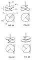
- the support and delivery means 10 can be designed as substantially vertically arranged screw spindles 35, as shown in Fig. 5.
- Such screw spindles can be arranged pair-wise opposite each other in a similar manner to the support and delivery means 10 described hereinabove, near two edges opposite each other of a construction element 2, or in case of a construction mat 2, near two cross or longitudinal wires 13, 11 located at a distance from each other.
- these edges or wires 13, 11 are taken up between successive windings 37.
- each screw spindle 35 preferably a rod-shaped element is arranged, which extends parallel to and at a short distance from this screw spindle 35. In this manner, cross or longitudinal wires 13, 11 extending between the windings 37 can be locked against the screw spindle, preventing them from slipping out of the windings 37.
- the support and delivery means 10 can be designed as shown in Fig. 6.
- a set of support and delivery means 10 is formed by a vertically arranged bar 40, which is provided, near a lower side, with two cams 42 H,L located one above the other.
- the cams 42 H,L are disc-shaped, missing a quarter of the circle segment.
- the cams 42 H,L are non-rotatably connected to the bar 40 such that the missing circle segments are rotated approximately 90° relative to each other.
- the mutual distance H between the cams is approximately equal to the thickness of the construction elements 2 to be manipulated, that is, in the case shown, the diameter of the wires 13.
- the cams 42 H,L are preferably provided so as to be slidable on the bar 40 such that the distance H can be adjusted as desired.
- a tube (not shown) can be provided, in which the bar can be pivotally bearing-mounted. This tube can then fulfill a same function as the tube parts 22 and ribs 29 in the embodiment shown in the Figs. 1-4, that is, to ensure that the support and delivery means are always at the right distance from the edge or wires 11,13 to be supported, so that the cams can move unhindered between a supporting and releasing position.
- the bars 40 with the cams 42 H,L can be arranged, in a manner similar to that described with reference to the previous embodiments, near an edge or wire 13, 11 of a construction element to be manipulated.
- a stack of construction elements 2 placed on the upper cams 42 H can be delivered one by one through rotation of the bar 40.
- the bar 40 with the cams 42 H,L is shown in perspective view and in top plan view.
- the upper cams 42 H are shown in continuous lines and the lower cams 42 L in interrupted lines.
- the lower cams 42 L are shown slightly smaller than the upper cams 42 H .
- the two cams 42 H,L preferably have the same dimensions.
- the upper cam 42 H In a first position (Fig. 6A), the upper cam 42 H extends under a cross wire 13 of a construction mat 2, and the cam 42 H can thus support this construction mat 2 or a stack of construction mats 2.
- the bar 40 When the bar 40 is rotated from this position through 90°, as shown in Fig. 6B, the missing circle segment is rotated in the direction of the cross wire 13, and the wire 13 is no longer supported. This will cause the mat or stack of mats to fall down one position on the lower cams 42 L .
- the bar 40 is further rotated through another 90° (Fig. 6C)
- the upper cam 42 H will slide between a lowermost and a second lowermost mat 2 and this cam 42 H thus takes over the stack of mats above the lowermost mat 2 from the lower cam 42 L .
- the bar 40 is rotated further to the starting position shown in Fig. 6A and the lowermost mat is isolated from the rest of the stack between the two cams 42 H,L , ready to be delivered.
- This delivery is done at the moment when the bar 40 is pivoted from the position shown in Fig. 6D to the position shown in Fig. 6A.
- the missing circle segment is maneuvered under the wire 13, so this wire is no longer supported by the cam 42 L and the construction mat is released while the superjacent stack is still supported by the upper cam 42 H .
- one piston assembly or other suitable drive means is sufficient. This contributes to a robust arrangement, which can, moreover, be safely and simply controlled, since the successive movements of the cams 42 H,L are mechanically fixed.
- the upper sides of the cams 42 H,L can be provided with friction-reducing means, such as, for instance, rollers, in order to facilitate the movement of the cams 42 H,L under the stack of construction elements.
- drive means other than the hydraulic drive means shown can be used, for instance electric or pneumatic drive means.
- a plurality of sets of cams can be placed above each other, allowing a plurality of elements to be isolated from the stack.
- the cams can also be arranged translatably around a substantially horizontal axis, with the cams being pivoted from a substantially horizontal, supporting position to a substantially vertical, non-supporting position.
- the cams can also be arranged so as to be translatable.
Landscapes
- Engineering & Computer Science (AREA)
- Mechanical Engineering (AREA)
- Architecture (AREA)
- Civil Engineering (AREA)
- Structural Engineering (AREA)
- De-Stacking Of Articles (AREA)
- Bending Of Plates, Rods, And Pipes (AREA)
- Sheets, Magazines, And Separation Thereof (AREA)
- Conveying And Assembling Of Building Elements In Situ (AREA)
Claims (20)
- Dispositif pour manipuler des éléments de construction essentiellement en forme de plaques (2), comprenant un cadre (3), muni de moyens de couplage (8) pour fixer le cadre (3) à des moyens de transport pour déplacer le cadre (3), des moyens de support (10) pour soulever et supporter une série d'éléments de construction (2) et des moyens de livraison pour la livraison des éléments de construction (2), caractérisé par le fait que durant l'utilisation les éléments de construction (2) sont soulevés à l'intérieur des moyens de support (25H ; 37; 42H) en forme empilée, et les moyens de livraison (25L ; 38 ; 42L) peuvent être actionnés afin d'être agencés au moins en partie sous les moyens de support (25H ; 37 ; 42H), en particulier la pile d'éléments de construction (2) soulevés à l'intérieur, dans lequel le support (25H ; 37 ; 42H) et les moyens de livraison (25L ; 38 ; 42L) peuvent coopérer de telle manière à permettre à un élément le plus bas de la pile d'être transféré depuis les moyens de support (25H ; 37 ; 42H) vers les moyens de livraison (25L; 38 ; 42L), isolant ainsi ledit élément le plus bas de la pile, après quoi cet élément peut être libéré par les moyens de livraison, permettant par conséquent aux éléments de construction (2) d'être livrés un par un.
- Dispositif selon la revendication 1, dans lequel les moyens de support (25H ; 37 ; 42H) sont agencés de façon à ce que, après la livraison d'un élément de construction le plus bas, les éléments de construction sus-jacents, restants (2) descendent d'une position.
- Dispositif selon la revendication 2, dans lequel les moyens de support (25H ; 37 ; 42H) sont agencés de façon à ce que la descente des éléments de construction (2) ait lieu sous la force de gravité.
- Dispositif selon l'une quelconque des revendications précédentes, dans lequel les moyens de support et de livraison (10) comprennent une série de premières cames (25H) et une série de secondes cames (25L), lesquelles cames (25H,L) sont, par série, mobiles indépendamment l'une de l'autre entre une première position de support dans laquelle les premières et secondes cames (25H,L) forment une première et une seconde surface de support respectivement, qui sont situées l'une au-dessus de l'autre et peuvent chacune supporter au moins une partie d'une pile d'éléments de construction (2), et une seconde position de libération, dans laquelle les séries de cames (25H,L) ne supportent pas les éléments de construction (2), au moins une partie de ceux-ci.
- Dispositif selon la revendication 4, dans lequel la distance perpendiculaire (H) entre la première et la seconde surface de support (25H,L) est approximativement égale à et de préférence légèrement supérieure à l'épaisseur (d) d'un élément de construction en forme de plaques (2).
- Dispositif selon la revendication 4 ou 5, dans lequel les premières et/ou les secondes cames (25H,L) peuvent pivoter entre la première et la seconde position.
- Dispositif selon la revendication 4 ou 5, dans lequel les premières et/ou les secondes cames (25H,L) sont transférables entre la première et la seconde position.
- Dispositif selon l'une quelconque des revendications 4-7, dans lequel les mouvements de la série de premières cames (25H ; 42H) et la série de secondes cames (25L ; 42L) sont couplés, de façon à ce que la série supérieure de cames (25H ; 42H) puisse seulement être déplacée depuis la première position de support vers la seconde position de libération, si la série inférieure de cames (25L ; 42L) se trouve dans la première position de support.
- Dispositif selon l'une quelconque des revendications précédentes, dans lequel les moyens de support et de livraison (10) sont agencés de façon à ce qu'ils permettent aux éléments de construction en forme de plaques (2) d'être soulevés un par un, dans lequel les moyens de livraison sont agencés pour se mettre en prise avec et ramasser un élément de construction et les moyens de support sont agencés pour supporter une pile d'éléments de construction ramassés plus tôt et dans lequel les moyens de support et de livraison sont agencés pour coopérer, afin de permettre à l'élément de construction ramassé par les moyens de livraison d'être transféré vers les moyens de support afin de faire partie de la pile supportée par lesdits moyens de support, laissant ainsi les éléments de livraison libres de ramasser un élément de construction qui suit.
- Dispositif selon l'une quelconque des revendications 5-9, dans lequel les premières et secondes cames (25H,L) sont supportées par des moyens de levage, de façon à ce que leurs positions mutuelles, vues en direction verticale, soient interchangeables, pour soulever les éléments de construction (2) un par un.
- Dispositif selon la revendication 1, dans lequel les moyens de support et de livraison (10) comprennent des arbres filetés agencés sensiblement verticalement (35), dans lequel, entre les enroulements (37 ; 38), des positions de soulèvement des éléments de construction (2) ont été formées et dans lequel les éléments de construction (2), à travers la rotation des arbres filetés (35), peuvent déplacer d'une place à la fois et, selon la direction de rotation, une position de soulèvement la plus basse (38) soulève, ou livre un élément de construction (2).
- Dispositif selon l'une quelconque des revendications précédentes, dans lequel les moyens de livraison et/ou de support (10) sont entraînés par des moyens d'entraînement à commande à distance (30).
- Dispositif selon la revendication 12, dans lequel les moyens d'entraînement (30) comprennent un montage de cylindre pneumatique ou hydraulique.
- Montage d'un dispositif selon l'une quelconque des revendications précédentes et une série d'éléments sensiblement en forme de plaques (2) caractérisé par le fait que les moyens de support et de livraison (10) sont installés à proximité d'un bord des éléments de construction (2).
- Montage d'un dispositif selon l'une quelconque des revendications 1-13 et une série d'éléments sensiblement en forme de plaques (2) caractérisé par le fait que les éléments de construction en forme de plaques (2) sont fabriqués à partir de fil métallique (11, 13) et que les moyens de support et de livraison (10) s'étendent à travers des mailles entre ces fils (11, 13), dans lequel les premières et secondes cames (25L,H; 37; 42L,H) dans la première position se mettent en prise sous ou derrière lesdits fils (11, 13).
- Montage selon la revendication 15, dans lequel des entretoises (29) sont prévues, pour maintenir une distance souhaitée entre les moyens de support et de livraison (10) et les fils (11, 13) des éléments de construction (2), de façon à ce que le mouvement des premières et secondes cames (25L,H ; 37 ; 42L,H) entre la première et la seconde position est possible sans entraves et que les cames puissent, dans une première position, s'étendre au moins en partie sous un fil (11, 13) et, dans une seconde position, soient situées à l'intérieur d'une maille.
- Procédé pour manipuler des éléments de construction sensiblement en forme de plaques (2) avec un dispositif selon l'une quelconque des revendications 1-13, caractérisé par le fait que les éléments de construction (2) sont soulevés un par un ou par pile, sont déplacés vers un emplacement souhaité et sont ensuite livrés un par un, dans l'ordre inverse du soulèvement.
- Procédé selon la revendication 17, dans lequel une pile d'éléments de construction (2) est livrée une par une au moyen d'au moins deux séries de cames mobiles (25L,H; 37 ; 42L,H), comprenant les étapes consistant à- déplacer une première série de cames (25L; 38 ; 42L) vers une première position, dans laquelle les cames s'étendent au moins en partie sous un élément de construction le plus bas de la pile ;- déplacer une seconde série de cames (25H ; 37 ; 42H) vers une première position, entre un élément le plus bas (2) de la pile et un élément sus-jacent ;- déplacer la première série de cames (25L; 38 ; 42L) vers une seconde position de non support, livrant ainsi l'élément le plus bas (2) ;- redéplacer la première série de cames (25L ; 38 ; 42L) vers une première position de support ;- déplacer la seconde série de cames (25H ; 37 ; 42H) vers une seconde position, abaissant ainsi au moins l'élément de construction le plus bas (2) de la pile restante sur la première série de cames ; après quoi les étapes ci-dessus peuvent être répétées jusqu'à ce que tous les éléments aient été livrés.
- Procédé selon la revendication 18, dans lequel la première et la seconde série de cames sont tout d'abord amenées dans la seconde position avant que les cames soient amenées à l'intérieur et/ou vers la pile d'éléments de construction qui doivent être manipulés, dans lequel la pile est ensuite livrée via lesdites étapes.
- Procédé selon la revendication 18 ou 19, dans lequel, après que tous les éléments de ladite pile aient été livrés, une pile suivante d'éléments de construction est livrée, en utilisant les cames, via lesdites étapes.
Applications Claiming Priority (2)
| Application Number | Priority Date | Filing Date | Title |
|---|---|---|---|
| NL1020961A NL1020961C1 (nl) | 2002-06-28 | 2002-06-28 | Inrichting en werkwijze voor het manipuleren van plaatvormige constructie-elementen. |
| NL1020961 | 2002-06-28 |
Publications (2)
| Publication Number | Publication Date |
|---|---|
| EP1375397A1 EP1375397A1 (fr) | 2004-01-02 |
| EP1375397B1 true EP1375397B1 (fr) | 2006-08-30 |
Family
ID=29717743
Family Applications (1)
| Application Number | Title | Priority Date | Filing Date |
|---|---|---|---|
| EP03077046A Expired - Lifetime EP1375397B1 (fr) | 2002-06-28 | 2003-06-30 | Dispositif et procédé pour manipuler des éléments de construction en forme de plaques |
Country Status (4)
| Country | Link |
|---|---|
| EP (1) | EP1375397B1 (fr) |
| AT (1) | ATE337991T1 (fr) |
| DE (1) | DE60307933T2 (fr) |
| NL (1) | NL1020961C1 (fr) |
Cited By (3)
| Publication number | Priority date | Publication date | Assignee | Title |
|---|---|---|---|---|
| CN102862776A (zh) * | 2011-07-05 | 2013-01-09 | 上海耐斯特液压设备有限公司 | 步进式重载滑移移运设备 |
| EP4502311A1 (fr) * | 2023-08-04 | 2025-02-05 | Wilhelmus Van Eekeres | Système mobile pour poser des panneaux isolants |
| EP4517027A1 (fr) * | 2023-08-30 | 2025-03-05 | The Roberts BV | Dispositif pour soulever au moins un produit plat de renforcement de materiau cimentaire |
Families Citing this family (6)
| Publication number | Priority date | Publication date | Assignee | Title |
|---|---|---|---|---|
| NL1032461C2 (nl) * | 2006-09-08 | 2008-03-12 | Sybe Bergsma | Inrichting en werkwijzen voor het manipuleren van constructie-elementen. |
| IT1396186B1 (it) * | 2009-09-23 | 2012-11-16 | Pigazzi Reti S R L | Manipolatore per reti. |
| NL2015175B1 (nl) * | 2015-07-15 | 2017-02-02 | Van Middendorp Montage B V | Draaginrichting voor het dragen van een stapel dakbedekkingsplaten. |
| JP6553565B2 (ja) * | 2016-09-09 | 2019-07-31 | 育良精機株式会社 | 棒材搬送装置 |
| CN111606045B (zh) * | 2019-09-26 | 2021-12-24 | 大连华枝金属制品制造有限公司 | 矩形铁丝框上料装置 |
| CN114291725B (zh) * | 2021-12-24 | 2023-03-10 | 中国建筑第二工程局有限公司 | 一种用于装配式建筑的吊装夹持装置及使用方法 |
Family Cites Families (4)
| Publication number | Priority date | Publication date | Assignee | Title |
|---|---|---|---|---|
| CH446403A (fr) * | 1967-02-10 | 1967-11-15 | Moll Robert | Dispositif pour la distribution automatique une à une de publications disposées en pile |
| DE2730626C3 (de) * | 1977-07-07 | 1980-05-29 | Oldenburger Betonsteinwerke Gmbh, 2906 Wardenburg | Greifer zum Zusammenfassen von einer Lage Pflastersteine zu einer Verlegeeinheit |
| CH654274A5 (fr) * | 1983-06-13 | 1986-02-14 | Rochat Charles L | Distributeur automatique pour pieces rigides plates. |
| IT1309756B1 (it) * | 1999-04-29 | 2002-01-30 | Clevertech Srl | Apparecchiatura per formare pile d'oggetti discoidali in numeroprefissato, in particolare per coperchi metallici di barattoli |
-
2002
- 2002-06-28 NL NL1020961A patent/NL1020961C1/nl not_active IP Right Cessation
-
2003
- 2003-06-30 AT AT03077046T patent/ATE337991T1/de not_active IP Right Cessation
- 2003-06-30 EP EP03077046A patent/EP1375397B1/fr not_active Expired - Lifetime
- 2003-06-30 DE DE60307933T patent/DE60307933T2/de not_active Expired - Fee Related
Cited By (5)
| Publication number | Priority date | Publication date | Assignee | Title |
|---|---|---|---|---|
| CN102862776A (zh) * | 2011-07-05 | 2013-01-09 | 上海耐斯特液压设备有限公司 | 步进式重载滑移移运设备 |
| EP4502311A1 (fr) * | 2023-08-04 | 2025-02-05 | Wilhelmus Van Eekeres | Système mobile pour poser des panneaux isolants |
| NL2035553B1 (en) * | 2023-08-04 | 2025-02-18 | Van Eekeres Wilhelmus | Mobile system for placing insulation boards |
| EP4517027A1 (fr) * | 2023-08-30 | 2025-03-05 | The Roberts BV | Dispositif pour soulever au moins un produit plat de renforcement de materiau cimentaire |
| WO2025045852A1 (fr) * | 2023-08-30 | 2025-03-06 | The Roberts Bv | Dispositif de levage d'au moins un produit de renforcement de matériau cimentaire plat |
Also Published As
| Publication number | Publication date |
|---|---|
| NL1020961C1 (nl) | 2003-12-30 |
| EP1375397A1 (fr) | 2004-01-02 |
| ATE337991T1 (de) | 2006-09-15 |
| DE60307933D1 (de) | 2006-10-12 |
| DE60307933T2 (de) | 2007-06-06 |
Similar Documents
| Publication | Publication Date | Title |
|---|---|---|
| EP1375397B1 (fr) | Dispositif et procédé pour manipuler des éléments de construction en forme de plaques | |
| EP4446079A2 (fr) | Machine pour enlever le coffrage d'une structure de plafond | |
| US12509331B2 (en) | Device for lifting a steel reinforcement mat | |
| EP2071081A1 (fr) | Machine de pavage | |
| JPH0977364A (ja) | ケーブル巻枠ドラム支持装置 | |
| EP2505713B1 (fr) | Procédé et dispositif de reconstitution d'une structure de chaussée | |
| KR101048036B1 (ko) | 전동식 호이스트 | |
| CN118704493A (zh) | 一种公路拱形骨架护坡砖提升铺装装置 | |
| EP3322867B1 (fr) | Set et procede pour transmettre une pile de panneaux de toit sur une lieu d'utilisation | |
| KR102530301B1 (ko) | 파이프 벤딩 장치 | |
| JPS62293084A (ja) | 容器の内壁を煉瓦で内張りする為の自動装置 | |
| US5184924A (en) | Method and equipment for transferring concrete slabs | |
| JP7519135B1 (ja) | ブロックの搬送据付 | |
| JP2952338B2 (ja) | 足場研掃装置 | |
| AU622994B2 (en) | Electrode handling system and machine | |
| US4081089A (en) | Arrangement for handling and preparation of base plates and the like such as, for example, casting molds | |
| KR200368508Y1 (ko) | 거푸집패널의 자동적재장치 | |
| JP2889977B2 (ja) | 足場研掃装置 | |
| GB2433955A (en) | Method of laying a plurality of railway sleepers | |
| US3319814A (en) | Device for manufacturing light weight building boards | |
| CN115744745B (zh) | 一种回顶构件拆除方法 | |
| US3292509A (en) | Picking device for mesh placing machine | |
| US20160068356A1 (en) | System and Method for Reusing or Recycling Building Material | |
| JPH10226489A (ja) | 建築用板の成形搬送システム | |
| JP2872044B2 (ja) | 構造物用部材の持上げ装置 |
Legal Events
| Date | Code | Title | Description |
|---|---|---|---|
| PUAI | Public reference made under article 153(3) epc to a published international application that has entered the european phase |
Free format text: ORIGINAL CODE: 0009012 |
|
| AK | Designated contracting states |
Kind code of ref document: A1 Designated state(s): AT BE BG CH CY CZ DE DK EE ES FI FR GB GR HU IE IT LI LU MC NL PT RO SE SI SK TR |
|
| AX | Request for extension of the european patent |
Extension state: AL LT LV MK |
|
| 17P | Request for examination filed |
Effective date: 20040702 |
|
| AKX | Designation fees paid |
Designated state(s): AT BE BG CH CY CZ DE DK EE ES FI FR GB GR HU IE IT LI LU MC NL PT RO SE SI SK TR |
|
| 17Q | First examination report despatched |
Effective date: 20041208 |
|
| GRAP | Despatch of communication of intention to grant a patent |
Free format text: ORIGINAL CODE: EPIDOSNIGR1 |
|
| GRAS | Grant fee paid |
Free format text: ORIGINAL CODE: EPIDOSNIGR3 |
|
| GRAA | (expected) grant |
Free format text: ORIGINAL CODE: 0009210 |
|
| AK | Designated contracting states |
Kind code of ref document: B1 Designated state(s): AT BE BG CH CY CZ DE DK EE ES FI FR GB GR HU IE IT LI LU MC NL PT RO SE SI SK TR |
|
| PG25 | Lapsed in a contracting state [announced via postgrant information from national office to epo] |
Ref country code: AT Free format text: LAPSE BECAUSE OF FAILURE TO SUBMIT A TRANSLATION OF THE DESCRIPTION OR TO PAY THE FEE WITHIN THE PRESCRIBED TIME-LIMIT Effective date: 20060830 Ref country code: LI Free format text: LAPSE BECAUSE OF FAILURE TO SUBMIT A TRANSLATION OF THE DESCRIPTION OR TO PAY THE FEE WITHIN THE PRESCRIBED TIME-LIMIT Effective date: 20060830 Ref country code: BE Free format text: LAPSE BECAUSE OF FAILURE TO SUBMIT A TRANSLATION OF THE DESCRIPTION OR TO PAY THE FEE WITHIN THE PRESCRIBED TIME-LIMIT Effective date: 20060830 Ref country code: RO Free format text: LAPSE BECAUSE OF FAILURE TO SUBMIT A TRANSLATION OF THE DESCRIPTION OR TO PAY THE FEE WITHIN THE PRESCRIBED TIME-LIMIT Effective date: 20060830 Ref country code: CZ Free format text: LAPSE BECAUSE OF FAILURE TO SUBMIT A TRANSLATION OF THE DESCRIPTION OR TO PAY THE FEE WITHIN THE PRESCRIBED TIME-LIMIT Effective date: 20060830 Ref country code: SI Free format text: LAPSE BECAUSE OF FAILURE TO SUBMIT A TRANSLATION OF THE DESCRIPTION OR TO PAY THE FEE WITHIN THE PRESCRIBED TIME-LIMIT Effective date: 20060830 Ref country code: SK Free format text: LAPSE BECAUSE OF FAILURE TO SUBMIT A TRANSLATION OF THE DESCRIPTION OR TO PAY THE FEE WITHIN THE PRESCRIBED TIME-LIMIT Effective date: 20060830 Ref country code: CH Free format text: LAPSE BECAUSE OF FAILURE TO SUBMIT A TRANSLATION OF THE DESCRIPTION OR TO PAY THE FEE WITHIN THE PRESCRIBED TIME-LIMIT Effective date: 20060830 Ref country code: FI Free format text: LAPSE BECAUSE OF FAILURE TO SUBMIT A TRANSLATION OF THE DESCRIPTION OR TO PAY THE FEE WITHIN THE PRESCRIBED TIME-LIMIT Effective date: 20060830 Ref country code: IT Free format text: LAPSE BECAUSE OF FAILURE TO SUBMIT A TRANSLATION OF THE DESCRIPTION OR TO PAY THE FEE WITHIN THE PRESCRIBED TIME-LIMIT;WARNING: LAPSES OF ITALIAN PATENTS WITH EFFECTIVE DATE BEFORE 2007 MAY HAVE OCCURRED AT ANY TIME BEFORE 2007. THE CORRECT EFFECTIVE DATE MAY BE DIFFERENT FROM THE ONE RECORDED. Effective date: 20060830 |
|
| REG | Reference to a national code |
Ref country code: GB Ref legal event code: FG4D |
|
| REG | Reference to a national code |
Ref country code: CH Ref legal event code: EP |
|
| REG | Reference to a national code |
Ref country code: IE Ref legal event code: FG4D |
|
| REF | Corresponds to: |
Ref document number: 60307933 Country of ref document: DE Date of ref document: 20061012 Kind code of ref document: P |
|
| PG25 | Lapsed in a contracting state [announced via postgrant information from national office to epo] |
Ref country code: DK Free format text: LAPSE BECAUSE OF FAILURE TO SUBMIT A TRANSLATION OF THE DESCRIPTION OR TO PAY THE FEE WITHIN THE PRESCRIBED TIME-LIMIT Effective date: 20061130 Ref country code: BG Free format text: LAPSE BECAUSE OF FAILURE TO SUBMIT A TRANSLATION OF THE DESCRIPTION OR TO PAY THE FEE WITHIN THE PRESCRIBED TIME-LIMIT Effective date: 20061130 Ref country code: SE Free format text: LAPSE BECAUSE OF FAILURE TO SUBMIT A TRANSLATION OF THE DESCRIPTION OR TO PAY THE FEE WITHIN THE PRESCRIBED TIME-LIMIT Effective date: 20061130 |
|
| PG25 | Lapsed in a contracting state [announced via postgrant information from national office to epo] |
Ref country code: ES Free format text: LAPSE BECAUSE OF FAILURE TO SUBMIT A TRANSLATION OF THE DESCRIPTION OR TO PAY THE FEE WITHIN THE PRESCRIBED TIME-LIMIT Effective date: 20061211 |
|
| PG25 | Lapsed in a contracting state [announced via postgrant information from national office to epo] |
Ref country code: PT Free format text: LAPSE BECAUSE OF FAILURE TO SUBMIT A TRANSLATION OF THE DESCRIPTION OR TO PAY THE FEE WITHIN THE PRESCRIBED TIME-LIMIT Effective date: 20070212 |
|
| REG | Reference to a national code |
Ref country code: CH Ref legal event code: PL |
|
| EN | Fr: translation not filed | ||
| PLBE | No opposition filed within time limit |
Free format text: ORIGINAL CODE: 0009261 |
|
| STAA | Information on the status of an ep patent application or granted ep patent |
Free format text: STATUS: NO OPPOSITION FILED WITHIN TIME LIMIT |
|
| 26N | No opposition filed |
Effective date: 20070531 |
|
| PG25 | Lapsed in a contracting state [announced via postgrant information from national office to epo] |
Ref country code: MC Free format text: LAPSE BECAUSE OF NON-PAYMENT OF DUE FEES Effective date: 20070630 |
|
| PG25 | Lapsed in a contracting state [announced via postgrant information from national office to epo] |
Ref country code: GR Free format text: LAPSE BECAUSE OF FAILURE TO SUBMIT A TRANSLATION OF THE DESCRIPTION OR TO PAY THE FEE WITHIN THE PRESCRIBED TIME-LIMIT Effective date: 20061201 Ref country code: FR Free format text: LAPSE BECAUSE OF FAILURE TO SUBMIT A TRANSLATION OF THE DESCRIPTION OR TO PAY THE FEE WITHIN THE PRESCRIBED TIME-LIMIT Effective date: 20070511 |
|
| PG25 | Lapsed in a contracting state [announced via postgrant information from national office to epo] |
Ref country code: EE Free format text: LAPSE BECAUSE OF FAILURE TO SUBMIT A TRANSLATION OF THE DESCRIPTION OR TO PAY THE FEE WITHIN THE PRESCRIBED TIME-LIMIT Effective date: 20060830 |
|
| PGFP | Annual fee paid to national office [announced via postgrant information from national office to epo] |
Ref country code: BE Payment date: 20080416 Year of fee payment: 6 |
|
| PG25 | Lapsed in a contracting state [announced via postgrant information from national office to epo] |
Ref country code: IE Free format text: LAPSE BECAUSE OF NON-PAYMENT OF DUE FEES Effective date: 20070702 |
|
| PGFP | Annual fee paid to national office [announced via postgrant information from national office to epo] |
Ref country code: DE Payment date: 20080819 Year of fee payment: 6 Ref country code: NL Payment date: 20080618 Year of fee payment: 6 |
|
| PG25 | Lapsed in a contracting state [announced via postgrant information from national office to epo] |
Ref country code: FR Free format text: LAPSE BECAUSE OF FAILURE TO SUBMIT A TRANSLATION OF THE DESCRIPTION OR TO PAY THE FEE WITHIN THE PRESCRIBED TIME-LIMIT Effective date: 20060830 |
|
| PGFP | Annual fee paid to national office [announced via postgrant information from national office to epo] |
Ref country code: GB Payment date: 20080617 Year of fee payment: 6 |
|
| PG25 | Lapsed in a contracting state [announced via postgrant information from national office to epo] |
Ref country code: LU Free format text: LAPSE BECAUSE OF NON-PAYMENT OF DUE FEES Effective date: 20070630 Ref country code: CY Free format text: LAPSE BECAUSE OF FAILURE TO SUBMIT A TRANSLATION OF THE DESCRIPTION OR TO PAY THE FEE WITHIN THE PRESCRIBED TIME-LIMIT Effective date: 20060830 |
|
| PG25 | Lapsed in a contracting state [announced via postgrant information from national office to epo] |
Ref country code: TR Free format text: LAPSE BECAUSE OF FAILURE TO SUBMIT A TRANSLATION OF THE DESCRIPTION OR TO PAY THE FEE WITHIN THE PRESCRIBED TIME-LIMIT Effective date: 20060830 Ref country code: HU Free format text: LAPSE BECAUSE OF FAILURE TO SUBMIT A TRANSLATION OF THE DESCRIPTION OR TO PAY THE FEE WITHIN THE PRESCRIBED TIME-LIMIT Effective date: 20070301 |
|
| BERE | Be: lapsed |
Owner name: BOUW & HANDELMIJ. NIJKERK B.V. Effective date: 20090630 |
|
| GBPC | Gb: european patent ceased through non-payment of renewal fee |
Effective date: 20090630 |
|
| NLV4 | Nl: lapsed or anulled due to non-payment of the annual fee |
Effective date: 20100101 |
|
| PG25 | Lapsed in a contracting state [announced via postgrant information from national office to epo] |
Ref country code: GB Free format text: LAPSE BECAUSE OF NON-PAYMENT OF DUE FEES Effective date: 20090630 |
|
| PG25 | Lapsed in a contracting state [announced via postgrant information from national office to epo] |
Ref country code: BE Free format text: LAPSE BECAUSE OF FAILURE TO SUBMIT A TRANSLATION OF THE DESCRIPTION OR TO PAY THE FEE WITHIN THE PRESCRIBED TIME-LIMIT Effective date: 20090630 Ref country code: DE Free format text: LAPSE BECAUSE OF NON-PAYMENT OF DUE FEES Effective date: 20100101 |
|
| PG25 | Lapsed in a contracting state [announced via postgrant information from national office to epo] |
Ref country code: NL Free format text: LAPSE BECAUSE OF NON-PAYMENT OF DUE FEES Effective date: 20100101 |