EP1375725A2 - Näh- oder Stickmaschine - Google Patents
Näh- oder Stickmaschine Download PDFInfo
- Publication number
- EP1375725A2 EP1375725A2 EP03405172A EP03405172A EP1375725A2 EP 1375725 A2 EP1375725 A2 EP 1375725A2 EP 03405172 A EP03405172 A EP 03405172A EP 03405172 A EP03405172 A EP 03405172A EP 1375725 A2 EP1375725 A2 EP 1375725A2
- Authority
- EP
- European Patent Office
- Prior art keywords
- light
- bobbin
- sewing
- thread
- embroidery machine
- Prior art date
- Legal status (The legal status is an assumption and is not a legal conclusion. Google has not performed a legal analysis and makes no representation as to the accuracy of the status listed.)
- Withdrawn
Links
Images


Classifications
-
- D—TEXTILES; PAPER
- D05—SEWING; EMBROIDERING; TUFTING
- D05B—SEWING
- D05B59/00—Applications of bobbin-winding or -changing devices; Indicating or control devices associated therewith
- D05B59/02—Devices for determining or indicating the length of thread still on the bobbin
Definitions
- the invention relates to a sewing or embroidery machine according to the preamble of claim 1.
- the upper thread also needle thread is called from one on or next to the sewing machine arranged coil supplied, the size of which is essentially is freely selectable.
- the lower thread is on a bobbin wrapped, which in the interior of the rotatably and drivable gripper of the sewing machine is inserted and is freely rotatable there. By the diameter of the The gripper consequently becomes the maximum size of the one in it lying bobbin determined.
- the spooled The bobbin thread quantity or the bobbin thread supply is in each Fall in relation to the upper thread supply on the outside arranged coil many times smaller and is also the bobbin is not visible from the outside when sewing, since they are inside the gripper housing and the latter located inside the sewing machine. This is why the monitoring of the current bobbin thread supply, the Bobbin thread withdrawal and thread end during embroidery or Sewing difficult. To make matters worse, often when sewing smaller pieces of material through the Operator a partially already filled Bobbin is covered with another thread. This other thread is already on the spool existing not connected. After consuming this the outer thread supply can no longer be seamed, although e.g. with known sensors on the coil core for example, 50% or 70% degree of filling determined becomes.
- Measuring devices are already from the prior art known to attempt the end and / or the Remaining amount of the bobbin thread on the bobbin and stop the sewing machine before that End of the lower thread from the upper thread through the sewing material is pulled out and before stitches are sewn on the underside of the fabric therefore not from a bobbin thread being held.
- WO 82/04447 describes a device for recognizing the End of thread on a bobbin of a sewing machine known.
- a light source sends a beam of light in the essentially radially from the outside through an opening in the Gripper housing in the direction of the axis of rotation of the gripper and the bobbin inserted in it.
- Tangential offset from the light source are two Light receiver arranged and also essentially on the axis of rotation of the hook and the bobbin directed and lie above a suitable in the gripper housing. attached opening.
- the object of the present invention is to create a Device with which the embroidery or sewing machine can be stopped as soon as the end of the lower thread is one predeterminable minimum length.
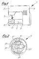
- the household sewing machine 1 shown in Figure 1 comprises a base plate 3, a lower or free arm 5, one Upper arm 7 with needle bar 9 and the machine housing 11, in which the drive elements are housed.
- a sideways arranged cover 13 at the front end of the forearm 5 is partially cut open to the position of the gripper 15 make visible.
- the hook 15 there is a lower thread bobbin, briefly a bobbin 17 with a Variety of breakthroughs 19 or non-reflective Markings in at least the front flange 21 used and visible ( Figures 2 and 3).
- the remaining Parts of the commercially available gripper 15 as that Gripper body 23, the drive shaft 25 and that on the Drive shaft 25 seated pinion 27 and that Thread catcher 29 with the tip 31 are not closer described.
- the hollow coil mandrel is also visible in this figure or core 33, at the ends of the two flanges 21 and 22 are attached.
- the openings 19 are formed. They lay concentric to the coil axis A.
- Alternatively to The example shown can also be one or two concentrically arranged rows of holes in both flanges 21 and 22 be present.
- the size, shape and number of Breakthroughs 19 is for the functionality of Invention without influence and therefore freely selectable.
- the bobbin 17 can be made of metal or plastic be made. It is preferably related to of the present invention made of metal and has a polished at least on the front flange 21 Surface on which is an optimal reflection of one on it directional focused beam of light.
- Axially spaced from surface 39 of the front flange 21 of the coil 17 is a light source 35 for visible or invisible light attached, for example one LED with which a light beam, preferably a pulsed one Beam of light 37 onto the front surface 39 of the flange 21 directed and reflected by this.
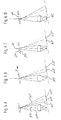
- the Reflection angle of a light beam 41 'on a plane 37 is constant as long as this on the axis of rotation of the Lower thread bobbin 17 perpendicular surface area of the front flange 21 strikes ( Figure 5A).
- the Light source 35 a conical light beam 37 in acute angle to the surface 39 of the flange 21. in the The focus according to FIGS. 5A-5D is F the rays 37 in front of the surface 39.
- the outermost Light beam 37 ' consequently strikes the point 38' Surface 39 and is from there as a reflection beam 41 ' in the reception area of a first light receiver 43 " reflected.
- Light-sensitive elements such as e.g. Photo transistors can be used.
- the second limiting light beam 37 " is in place 38 "reflected on the surface 39 and as Reflection beam 41 "in the area of the second Light receiver 43 'reflected. Shown in the Figures are only the outermost rays of the beam. As long as the light rays 37 consequently on the surface 39, formed by the webs 40 fall between two openings 19, by both Light receivers 43 ', 43 "receive light simultaneously the further rotation of the coil 21 hits the bundle limiting light beam 37 "no longer on the surface 39, but penetrates the opening 19 and is therefore, if there is a thread supply behind the Breakthroughs are present, reflected on this. The However, reflection is only minimal, so that reflected light beam 41 "is very weak and as such is recognized by the light receiver 43 '.
- the delimiting light beam 37 ' still falls on the Surface 39 and is used as a strong reflection beam 41 ' reflects what is received by the receiving part 43 "accordingly is recognized.
- the sewing machine electronics recognize by the elimination of the strong reflection light in the area of the Light receiver 43 'the direction of rotation of the coil in the direction of the arrow v, in Figures 5, 6 and 7 from left to right right, clockwise in Figure 4.
- By the further Rotation of the spool 17 hits both Limiting light beams 37 'and 37 "in the area of a Breakthrough 19 and are therefore only weak reflects what is caused by the two light receivers 43 'and 43 "is recognized (FIG. 5C).
- the Coil 17 or the coil flange 21 hits the Boundary beam 37 "on the surface 39 of the Opening 19 lying web 40.
- the beam 37 " is completely as a limiting beam 41 "to the light receiver 43 'reflected and recognized by it.
- the one in the Breakthrough 19 falling beam 37 ' is only weak as Beam 41 'is reflected and received by receiver 43 " such recognized.
- the coil flange surface markings e.g. black, have little light reflecting surfaces.
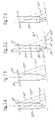
- FIGS. 7A-7D is by a correspondingly trained lens 36 Beams 37 of the light source 35 in parallel running light beams 37 'and 37 "bundled reflected rays 41 'and 41 "fall according to Representation in Figures 7A-7D on the light receiver 43 'and 43 ".
- the evaluation electronics is connected to another sensor that detects the speed n 0 of the main shaft or the drive motor by the detected standstill the bobbin 17 should not be interpreted as a thread break or thread end when the sewing is interrupted.
- This arrangement allows these items without additional Holding devices and thus also at no additional cost the existing parts (cover 13) of the sewing machine 1 attach and when opening the lid access to the Bobbin 17 and to expose these elements.
- the preferably in front of the light source 35 and the light receiver 43 'and 43 "lenses 36 easily removed from fluff.
- the observed direction of rotation of the coil can also be determined whether the coil is properly in the Bobbin case is inserted. From the ratio stitch type, Stitch speed, bobbin rotation speed the bobbin thread supply can also be calculated.
Landscapes
- Engineering & Computer Science (AREA)
- Textile Engineering (AREA)
- Sewing Machines And Sewing (AREA)
Abstract
Description
- Figur 1
- eine schematische Darstellung der Seitenansicht einer Nähmaschine (Unterarm teilweise aufgeschnitten),
- Figur 2
- eine vergrösserte stirnseitige Darstellung des Greifers mit eingesetzter Unterfadenspule,
- Figur 3
- eine seitliche Darstellung des Greifers in Figur 2,
- Figur 4
- eine perspektivische Darstellung der Unterfadenspule mit Sensoren,
- Figuren 5A-5D
- eine graphische Darstellung der Reflektion der Strahlen der Lichtquelle auf die beiden Lichtempfänger in vier unterschiedlichen Stellungen der Spule bezüglich der Lichtempfänger mit einem Brennpunkt vor der Spulenflanke,
- Figuren 6A-6D
- eine graphische Darstellung der Reflektion der Strahlen der Lichtquelle auf die beiden Lichtempfänger in vier unterschiedlichen Stellungen der Spule bezüglich der Lichtempfänger mit einem Brennpunkt hinter der Spulenflanke und
- Figuren 7A-7D
- eine graphische Darstellung der Reflektion bei parallel verlaufenden Strahlen der Lichtquelle auf die beiden Lichtempfänger in vier unterschiedlichen Stellungen der Spule bezüglich des Lichtempfängers.
Claims (6)
- Näh- oder Stickmaschine (1) mit einem von einem Antriebsmotor antreibbaren Greifer (15) und mit einer im Greifer (15) drehbar gelagerten Unterfadenspule (17) zur Aufnahme eines Unterfadenvorrats mit einem hohlzylindrischen Dorn und an den Dornenden aufgesetzten ringförmigen Flanschen (21,22), von denen mindestens einer (21) mit Durchbrüchen (19) durchsetzt oder nicht reflektierenden Markierungen versehen ist und mit einer Lichtquelle (35) sowie zwei Lichtempfängern (43',43") zum Empfangen der von der Lichtquelle (35) emittierten Lichtstrahlen (37) an zwei beabstandeten Stellen, sowie eine Rechen- und Steuereinheit zur Verarbeitung der von den Lichtempfängern (43', 43") gelieferten Signalen, dadurch gekennzeichnet, dass die Lichtquelle (35) und die beiden Lichtempfänger (43',43") axial beabstandet vor dem Flansch (21) mit den Durchbrüchen (19) oder mit Markierungen angeordnet sind und dass die Lichtstrahlen (37) in einem spitzen Winkel auf die Oberfläche (39) des vorne liegenden Flansches (21) gerichtet sind.
- Näh- oder Stickmaschine nach Anspruch 1, dadurch gekennzeichnet, dass zum Feststellen der Drehgeschwindigkeit der Hauptwelle oder des Antriebmotors ein Sensor mit der Steuereinheit verbunden ist.
- Näh- oder Stickmaschine nach Anspruch 1 oder 2, dadurch gekennzeichnet, dass die Lichtquelle (35) ein kegelförmiges Lichtstrahlenbündel (37) aussendet, dessen Brennpunkt (F) vor oder hinter dem Flansch (21) der Spule (17) liegt.
- Näh- oder Stickmaschine nach Anspruch 1 oder 2, dadurch gekennzeichnet, dass die Lichtquelle (35) ein Lichtstrahlenbündel (37) mit parallel verlaufenden Lichtstrahlen aussendet.
- Näh- oder Stickmaschine nach einem der Ansprüche 1 bis 4, dadurch gekennzeichnet, dass die Lichtstrahlen des Lichtstrahlenbündels (37), die auf die Oberfläche (39) des vorne liegenden Flansches (21) der Spule (17) auftreten und an dieser reflektierbar sind, entweder von je einem der beiden Lichtempfänger (43') oder (43") allein oder von beiden Lichtempfängern (43',43") gemeinsam empfangbar sind.
- Näh- oder Stickmaschine nach Anspruch 5, dadurch gekennzeichnet, dass die Intensität und die Reihenfolge des Auftreffens der reflektierten Lichtstrahlen (37) auf die Lichtempfänger (43',43") in Abhängigkeit von der Reflektion an der Flanschoberfläche (39) oder der geringeren Reflektion an den in den Durchbrüchen (19) sichtbaren Fäden auf der Spule (17) gemessen und durch die Steuerung auswertbar ist.
Applications Claiming Priority (2)
| Application Number | Priority Date | Filing Date | Title |
|---|---|---|---|
| CH00893/02A CH709887B1 (de) | 2002-05-30 | 2002-05-30 | Näh- oder Stickmaschine. |
| CH8932002 | 2002-05-30 |
Publications (2)
| Publication Number | Publication Date |
|---|---|
| EP1375725A2 true EP1375725A2 (de) | 2004-01-02 |
| EP1375725A3 EP1375725A3 (de) | 2005-01-26 |
Family
ID=29555536
Family Applications (1)
| Application Number | Title | Priority Date | Filing Date |
|---|---|---|---|
| EP03405172A Withdrawn EP1375725A3 (de) | 2002-05-30 | 2003-03-12 | Näh- oder Stickmaschine |
Country Status (3)
| Country | Link |
|---|---|
| US (1) | US6810824B2 (de) |
| EP (1) | EP1375725A3 (de) |
| CH (1) | CH709887B1 (de) |
Cited By (1)
| Publication number | Priority date | Publication date | Assignee | Title |
|---|---|---|---|---|
| EP1700941A1 (de) | 2005-03-11 | 2006-09-13 | Fritz Gegauf Aktiengesellschaft | Näh-oder Stickmaschine |
Families Citing this family (9)
| Publication number | Priority date | Publication date | Assignee | Title |
|---|---|---|---|---|
| KR100471639B1 (ko) * | 2004-11-04 | 2005-03-14 | 윤경기 | 잔사를 감지하는 재봉틀의 밑실 공급장치 |
| WO2006071786A2 (en) * | 2004-12-24 | 2006-07-06 | Koerner Ralph J | Stitching method and apparatus employing bottom thread payout detection |
| US7793602B2 (en) * | 2004-12-24 | 2010-09-14 | Koemer Ralph J | Stitching method and apparatus employing thread longitudinal movement detection |
| EP1811073A2 (de) * | 2006-01-18 | 2007-07-25 | BERNINA International AG | Nähmaschine und Verfahren zum Erfassen von Bewegungen bei Nähmaschinen |
| WO2007143062A2 (en) * | 2006-05-31 | 2007-12-13 | Koerner Ralph J | Stitching method and apparatus employing thread payout detection |
| DE102014220209A1 (de) * | 2014-10-07 | 2016-04-07 | Dürkopp Adler AG | Sensorbaugruppe für eine Nähmaschine |
| JP6867139B2 (ja) * | 2016-11-09 | 2021-04-28 | Juki株式会社 | ミシンの下糸巻き装置及びミシン |
| CN112281331B (zh) * | 2020-10-26 | 2022-07-19 | 中山市时泰日用制品有限公司 | 缝纫机中的底线线量检测装置 |
| CN115538055A (zh) * | 2021-06-30 | 2022-12-30 | 浙江中捷缝纫科技有限公司 | 绕线装置和绕线检测方法 |
Family Cites Families (5)
| Publication number | Priority date | Publication date | Assignee | Title |
|---|---|---|---|---|
| DE3046260C2 (de) | 1980-12-09 | 1983-11-03 | Daimler-Benz Ag, 7000 Stuttgart | Vorrichtung zur automatischen Nahtkontrolle an Doppelkettenstich-Nähmaschinen |
| SE426717B (sv) * | 1981-06-16 | 1983-02-07 | Husqvarna Ab | Signalanordning i symaskin for avkenning och indikering av tradinnehallet pa en spole |
| JP2762690B2 (ja) * | 1990-05-18 | 1998-06-04 | ブラザー工業株式会社 | ミシンの下糸量検出装置 |
| DE4116788C1 (de) * | 1991-05-23 | 1992-06-25 | G.M. Pfaff Ag, 6750 Kaiserslautern, De | |
| DE10140636C1 (de) * | 2001-08-13 | 2003-04-24 | Pfaff Ind Masch | Einrichtung zum Überwachen des Spulenfadens an Doppelsteppstich-Nähmaschinen |
-
2002
- 2002-05-30 CH CH00893/02A patent/CH709887B1/de not_active IP Right Cessation
-
2003
- 2003-03-12 EP EP03405172A patent/EP1375725A3/de not_active Withdrawn
- 2003-05-29 US US10/447,870 patent/US6810824B2/en not_active Expired - Lifetime
Cited By (2)
| Publication number | Priority date | Publication date | Assignee | Title |
|---|---|---|---|---|
| EP1700941A1 (de) | 2005-03-11 | 2006-09-13 | Fritz Gegauf Aktiengesellschaft | Näh-oder Stickmaschine |
| US7162966B2 (en) | 2005-03-11 | 2007-01-16 | Itz Gegauf Aktiengesellschaft Rnina-Nahmaschinenfabrik | Sewing or embroidery machine |
Also Published As
| Publication number | Publication date |
|---|---|
| US6810824B2 (en) | 2004-11-02 |
| EP1375725A3 (de) | 2005-01-26 |
| US20030221601A1 (en) | 2003-12-04 |
| CH709887B1 (de) | 2016-01-29 |
Similar Documents
| Publication | Publication Date | Title |
|---|---|---|
| DE10140636C1 (de) | Einrichtung zum Überwachen des Spulenfadens an Doppelsteppstich-Nähmaschinen | |
| EP1394310B1 (de) | Verfahren zur Bestimmung des Unterfadenvorrats und eine Nähmaschine mit einer Unterfadenvorrats-Uberwachung | |
| EP0838422A1 (de) | Vorrichtung zum Aufwickeln eines Fadens auf eine Spule | |
| DE4141207A1 (de) | Vorrichtung zum ermitteln einer restmenge eines um einen spulenkern aufgewickelten spulenfadens | |
| DE4116638A1 (de) | Vorrichtung zum feststellen eines auf eine spule aufgewickelten fadenrestes einer naehmaschine | |
| CH709887B1 (de) | Näh- oder Stickmaschine. | |
| EP0837829B1 (de) | Optoelektronische sensorvorrichtung und schussfaden-messspeichergerät | |
| DE19510808C1 (de) | Verfahren und Vorrichtung zum Erkennen einer Restmenge des Greiferfadens bei einer Nähmaschine | |
| DE60224153T2 (de) | Vorrichtung zum Umhüllen von Körpern, insbesondere von Erntegutballen | |
| EP0424395B1 (de) | Fadenwächter | |
| DE3832984C2 (de) | Verfahren und Vorrichtung zur Fadenbruchanzeige in Fadenscharen | |
| DE102015001589A1 (de) | Garnspulvorrichtung | |
| CH648118A5 (de) | Vorrichtung zum messen der laenge eines auf einem wickel aufgespulten endlosen materials. | |
| EP1700941B1 (de) | Näh-oder Stickmaschine | |
| DE19545891A1 (de) | Verfahren zum Überwachen der Abtastverhältnisse beim Steuern einer Fadenliefervorrichtung | |
| DE3833969A1 (de) | Garnzufuhreinrichtung | |
| DE69414645T2 (de) | Verbessertes Spulenwickelverfahren und Spulmaschinen zu dessen Durchführung | |
| DE4222377A1 (de) | Verfahren und Vorrichtung zum Erfassen eines auf einer Kreuzspule angeordneten Fadenendes | |
| DE69714519T2 (de) | Vorrichtung zur Qualitätsüberprüfung von Spulen | |
| DE3707321C1 (de) | Naehmaschine mit einem Fadenwaechter fuer den Faden der Spule | |
| DE4031058C1 (en) | Device for bobbin thread end to be sewn in sewing machine - comprises unit to emit light which is reflected by bobbin web to the opening height | |
| DE3625963C2 (de) | ||
| DE3635140A1 (de) | Optische abtastvorrichtung zur ermittlung einer leerlaufenden vorlagenspule bei einer spinn- oder zwirnmaschine | |
| EP1225149B1 (de) | Vorrichtung an einem Direkt-Rovingwickler zum berührungslosen Erfassen des Istdurchmessers der Rovingspule und Direkt-Rovingwickler mit einer solchen Vorrichtung | |
| EP2163667B1 (de) | Drehgatter einer Musterkettenschärmaschine und Musterkettenschärmaschine |
Legal Events
| Date | Code | Title | Description |
|---|---|---|---|
| PUAI | Public reference made under article 153(3) epc to a published international application that has entered the european phase |
Free format text: ORIGINAL CODE: 0009012 |
|
| AK | Designated contracting states |
Kind code of ref document: A2 Designated state(s): AT BE BG CH CY CZ DE DK EE ES FI FR GB GR HU IE IT LI LU MC NL PT RO SE SI SK TR |
|
| AX | Request for extension of the european patent |
Extension state: AL LT LV MK |
|
| PUAL | Search report despatched |
Free format text: ORIGINAL CODE: 0009013 |
|
| AK | Designated contracting states |
Kind code of ref document: A3 Designated state(s): AT BE BG CH CY CZ DE DK EE ES FI FR GB GR HU IE IT LI LU MC NL PT RO SE SI SK TR |
|
| AX | Request for extension of the european patent |
Extension state: AL LT LV MK |
|
| 17P | Request for examination filed |
Effective date: 20050228 |
|
| AKX | Designation fees paid |
Designated state(s): AT BE BG CH CY CZ DE DK EE ES FI FR GB GR HU IE IT LI LU MC NL PT RO SE SI SK TR |
|
| RAP1 | Party data changed (applicant data changed or rights of an application transferred) |
Owner name: FRITZ GEGAUF AG |
|
| RAP1 | Party data changed (applicant data changed or rights of an application transferred) |
Owner name: BERNINA INTERNATIONAL AG |
|
| STAA | Information on the status of an ep patent application or granted ep patent |
Free format text: STATUS: THE APPLICATION IS DEEMED TO BE WITHDRAWN |
|
| 18D | Application deemed to be withdrawn |
Effective date: 20111001 |