EP1375850A2 - Système de traitement de gaz d'échappement - Google Patents
Système de traitement de gaz d'échappement Download PDFInfo
- Publication number
- EP1375850A2 EP1375850A2 EP03253961A EP03253961A EP1375850A2 EP 1375850 A2 EP1375850 A2 EP 1375850A2 EP 03253961 A EP03253961 A EP 03253961A EP 03253961 A EP03253961 A EP 03253961A EP 1375850 A2 EP1375850 A2 EP 1375850A2
- Authority
- EP
- European Patent Office
- Prior art keywords
- exhaust gas
- particle shape
- cyclone
- processing apparatus
- nox
- Prior art date
- Legal status (The legal status is an assumption and is not a legal conclusion. Google has not performed a legal analysis and makes no representation as to the accuracy of the status listed.)
- Withdrawn
Links
Images




Classifications
-
- F—MECHANICAL ENGINEERING; LIGHTING; HEATING; WEAPONS; BLASTING
- F01—MACHINES OR ENGINES IN GENERAL; ENGINE PLANTS IN GENERAL; STEAM ENGINES
- F01N—GAS-FLOW SILENCERS OR EXHAUST APPARATUS FOR MACHINES OR ENGINES IN GENERAL; GAS-FLOW SILENCERS OR EXHAUST APPARATUS FOR INTERNAL-COMBUSTION ENGINES
- F01N3/00—Exhaust or silencing apparatus having means for purifying, rendering innocuous, or otherwise treating exhaust
- F01N3/02—Exhaust or silencing apparatus having means for purifying, rendering innocuous, or otherwise treating exhaust for cooling, or for removing solid constituents of, exhaust
- F01N3/037—Exhaust or silencing apparatus having means for purifying, rendering innocuous, or otherwise treating exhaust for cooling, or for removing solid constituents of, exhaust by means of inertial or centrifugal separators, e.g. of cyclone type, optionally combined or associated with agglomerators
-
- B—PERFORMING OPERATIONS; TRANSPORTING
- B01—PHYSICAL OR CHEMICAL PROCESSES OR APPARATUS IN GENERAL
- B01D—SEPARATION
- B01D45/00—Separating dispersed particles from gases or vapours by gravity, inertia, or centrifugal forces
- B01D45/12—Separating dispersed particles from gases or vapours by gravity, inertia, or centrifugal forces by centrifugal forces
- B01D45/16—Separating dispersed particles from gases or vapours by gravity, inertia, or centrifugal forces by centrifugal forces generated by the winding course of the gas stream, the centrifugal forces being generated solely or partly by mechanical means, e.g. fixed swirl vanes
-
- B—PERFORMING OPERATIONS; TRANSPORTING
- B01—PHYSICAL OR CHEMICAL PROCESSES OR APPARATUS IN GENERAL
- B01D—SEPARATION
- B01D53/00—Separation of gases or vapours; Recovering vapours of volatile solvents from gases; Chemical or biological purification of waste gases, e.g. engine exhaust gases, smoke, fumes, flue gases, aerosols
- B01D53/32—Separation of gases or vapours; Recovering vapours of volatile solvents from gases; Chemical or biological purification of waste gases, e.g. engine exhaust gases, smoke, fumes, flue gases, aerosols by electrical effects other than those provided for in group B01D61/00
- B01D53/323—Separation of gases or vapours; Recovering vapours of volatile solvents from gases; Chemical or biological purification of waste gases, e.g. engine exhaust gases, smoke, fumes, flue gases, aerosols by electrical effects other than those provided for in group B01D61/00 by electrostatic effects or by high-voltage electric fields
-
- B—PERFORMING OPERATIONS; TRANSPORTING
- B01—PHYSICAL OR CHEMICAL PROCESSES OR APPARATUS IN GENERAL
- B01D—SEPARATION
- B01D53/00—Separation of gases or vapours; Recovering vapours of volatile solvents from gases; Chemical or biological purification of waste gases, e.g. engine exhaust gases, smoke, fumes, flue gases, aerosols
- B01D53/34—Chemical or biological purification of waste gases
- B01D53/92—Chemical or biological purification of waste gases of engine exhaust gases
-
- B—PERFORMING OPERATIONS; TRANSPORTING
- B03—SEPARATION OF SOLID MATERIALS USING LIQUIDS OR USING PNEUMATIC TABLES OR JIGS; MAGNETIC OR ELECTROSTATIC SEPARATION OF SOLID MATERIALS FROM SOLID MATERIALS OR FLUIDS; SEPARATION BY HIGH-VOLTAGE ELECTRIC FIELDS
- B03C—MAGNETIC OR ELECTROSTATIC SEPARATION OF SOLID MATERIALS FROM SOLID MATERIALS OR FLUIDS; SEPARATION BY HIGH-VOLTAGE ELECTRIC FIELDS
- B03C3/00—Separating dispersed particles from gases or vapour, e.g. air, by electrostatic effect
- B03C3/02—Plant or installations having external electricity supply
- B03C3/04—Plant or installations having external electricity supply dry type
- B03C3/14—Plant or installations having external electricity supply dry type characterised by the additional use of mechanical effects, e.g. gravity
- B03C3/15—Centrifugal forces
-
- B—PERFORMING OPERATIONS; TRANSPORTING
- B03—SEPARATION OF SOLID MATERIALS USING LIQUIDS OR USING PNEUMATIC TABLES OR JIGS; MAGNETIC OR ELECTROSTATIC SEPARATION OF SOLID MATERIALS FROM SOLID MATERIALS OR FLUIDS; SEPARATION BY HIGH-VOLTAGE ELECTRIC FIELDS
- B03C—MAGNETIC OR ELECTROSTATIC SEPARATION OF SOLID MATERIALS FROM SOLID MATERIALS OR FLUIDS; SEPARATION BY HIGH-VOLTAGE ELECTRIC FIELDS
- B03C3/00—Separating dispersed particles from gases or vapour, e.g. air, by electrostatic effect
- B03C3/34—Constructional details or accessories or operation thereof
- B03C3/40—Electrode constructions
- B03C3/45—Collecting-electrodes
- B03C3/47—Collecting-electrodes flat, e.g. plates, discs, gratings
-
- F—MECHANICAL ENGINEERING; LIGHTING; HEATING; WEAPONS; BLASTING
- F01—MACHINES OR ENGINES IN GENERAL; ENGINE PLANTS IN GENERAL; STEAM ENGINES
- F01N—GAS-FLOW SILENCERS OR EXHAUST APPARATUS FOR MACHINES OR ENGINES IN GENERAL; GAS-FLOW SILENCERS OR EXHAUST APPARATUS FOR INTERNAL-COMBUSTION ENGINES
- F01N3/00—Exhaust or silencing apparatus having means for purifying, rendering innocuous, or otherwise treating exhaust
- F01N3/01—Exhaust or silencing apparatus having means for purifying, rendering innocuous, or otherwise treating exhaust by means of electric or electrostatic separators
-
- F—MECHANICAL ENGINEERING; LIGHTING; HEATING; WEAPONS; BLASTING
- F01—MACHINES OR ENGINES IN GENERAL; ENGINE PLANTS IN GENERAL; STEAM ENGINES
- F01N—GAS-FLOW SILENCERS OR EXHAUST APPARATUS FOR MACHINES OR ENGINES IN GENERAL; GAS-FLOW SILENCERS OR EXHAUST APPARATUS FOR INTERNAL-COMBUSTION ENGINES
- F01N3/00—Exhaust or silencing apparatus having means for purifying, rendering innocuous, or otherwise treating exhaust
- F01N3/02—Exhaust or silencing apparatus having means for purifying, rendering innocuous, or otherwise treating exhaust for cooling, or for removing solid constituents of, exhaust
- F01N3/021—Exhaust or silencing apparatus having means for purifying, rendering innocuous, or otherwise treating exhaust for cooling, or for removing solid constituents of, exhaust by means of filters
- F01N3/023—Exhaust or silencing apparatus having means for purifying, rendering innocuous, or otherwise treating exhaust for cooling, or for removing solid constituents of, exhaust by means of filters using means for regenerating the filters, e.g. by burning trapped particles
- F01N3/0231—Exhaust or silencing apparatus having means for purifying, rendering innocuous, or otherwise treating exhaust for cooling, or for removing solid constituents of, exhaust by means of filters using means for regenerating the filters, e.g. by burning trapped particles using special exhaust apparatus upstream of the filter for producing nitrogen dioxide, e.g. for continuous filter regeneration systems [CRT]
-
- F—MECHANICAL ENGINEERING; LIGHTING; HEATING; WEAPONS; BLASTING
- F01—MACHINES OR ENGINES IN GENERAL; ENGINE PLANTS IN GENERAL; STEAM ENGINES
- F01N—GAS-FLOW SILENCERS OR EXHAUST APPARATUS FOR MACHINES OR ENGINES IN GENERAL; GAS-FLOW SILENCERS OR EXHAUST APPARATUS FOR INTERNAL-COMBUSTION ENGINES
- F01N3/00—Exhaust or silencing apparatus having means for purifying, rendering innocuous, or otherwise treating exhaust
- F01N3/08—Exhaust or silencing apparatus having means for purifying, rendering innocuous, or otherwise treating exhaust for rendering innocuous
- F01N3/0892—Electric or magnetic treatment, e.g. dissociation of noxious components
-
- B—PERFORMING OPERATIONS; TRANSPORTING
- B03—SEPARATION OF SOLID MATERIALS USING LIQUIDS OR USING PNEUMATIC TABLES OR JIGS; MAGNETIC OR ELECTROSTATIC SEPARATION OF SOLID MATERIALS FROM SOLID MATERIALS OR FLUIDS; SEPARATION BY HIGH-VOLTAGE ELECTRIC FIELDS
- B03C—MAGNETIC OR ELECTROSTATIC SEPARATION OF SOLID MATERIALS FROM SOLID MATERIALS OR FLUIDS; SEPARATION BY HIGH-VOLTAGE ELECTRIC FIELDS
- B03C2201/00—Details of magnetic or electrostatic separation
- B03C2201/30—Details of magnetic or electrostatic separation for use in or with vehicles
-
- F—MECHANICAL ENGINEERING; LIGHTING; HEATING; WEAPONS; BLASTING
- F01—MACHINES OR ENGINES IN GENERAL; ENGINE PLANTS IN GENERAL; STEAM ENGINES
- F01N—GAS-FLOW SILENCERS OR EXHAUST APPARATUS FOR MACHINES OR ENGINES IN GENERAL; GAS-FLOW SILENCERS OR EXHAUST APPARATUS FOR INTERNAL-COMBUSTION ENGINES
- F01N2260/00—Exhaust treating devices having provisions not otherwise provided for
- F01N2260/06—Exhaust treating devices having provisions not otherwise provided for for improving exhaust evacuation or circulation, or reducing back-pressure
Definitions
- the present invention relates to a n exhaust gas processing system and an exhaust gas processing apparatus in which a composition of a harmful chemical substance of an exhaust gas etc. which is exhausted from a boiler including NOx, a particle shape substance and hydrocarbon and an engine etc. and a chemical reaction etc. of a harmful substance are promoted and a chemical work and an environment machine and apparatus.
- NOx removal for a diesel vehicle it take a counter -measurement with a high pressure injection of the engine and a figuration of a combustion chamber but with only this counter measurement a satisfied technique has not established.
- a device in which as to NOx in the exhaust gas using a noble metal catalyst such as a platinum and paradigm etc. NOx generates and using a catalyst in a post-process the fine particles are decomposed but NOx reduction effect is low about 15 % and a regular processing apparatus has not established.
- a three -way catalyst in which the noble metal is contained mainly but this is high cost and is not to be practical use. In this, since the platinum used in the catalyst lowers the catalyst function due to the sulfur in the fuel, a spread of a low sulfur fuel sets as premise.
- the particle shape substance is composed completely using a low cost catalyst under a low temperature about 300 C or not using completely the catalyst.
- An object of the present invention is to provide an exhaust gas processing apparatus wherein in which the particle shape substances are separated and removed and NOx in the exhaust gas is decomposed using discharge.
- Another object of the present invention is to provide an exhaust gas processing apparatus wherein in which the particle shape substances are processed with a real time by complying with the operation states of an engine.
- the generation of NO 2 is carried out not using the noble metals such as platinum as the catalyst. Namely, the particle shape substance having the large particle diameter is separated by the centrifugal force using the cyclone, and the particle shape substance having the small particle diameter is removed using the electric dust collection. Next, NOx is decomposed using a barrier discharge etc. and NO 2 necessary to decompose the particle shape substance is generated in NO in NOx.
- one of the electrodes is formed by the anode oxidation with a long line shape, a belt shape, a rod shape, or a plate shape, and an outer skin of a superior permeability performance and thin insulati on body such as a ceramic, and a heat resistance silicone etc. is covered.
- Another of the electrodes is formed with a bear wire suited to a shape of the insulation core wire and along to the insulation core wire is arranged closely in a parallel shape, a rectangular shape, a spiral shape, a net shape, or a zigzag shape by performing the anode oxidation film and the ceramics coating to obtain the anti -environment performance and then the ozone and the barrier discharge is generated effectively.
- the alternating current high voltage is applied to the electrodes and the voltage and the frequency number are changed, in conform to the raise of the voltage, NO in an exhaust gas containing a residual oxygen is lowered and it has became zero when it is reached to same voltage.
- NO 2 is increased gradually slightly (less than 1/10) at first in comparison with NO and NO 2 is existed in a range of zero and it is shown a peak value and when the voltage is lowered further it is reduced gradually and becomes zero soon. At this time point, NOx is gone out of existence completely.
- the particle shape substance is decomposed completely using a low cost catalyst under a low temperature about 300 C, since the amount of NO 2 and the ozone (more than 400 C, this has became the active oxygen) is controlled freely with the volt age, the frequency number and the oxides of vanadium and molybdenum, the zeolite and the alumina are used as the catalyst and under the low temperature about 300 C, without of the bare use of the noble metal the particle shape substance is decomposed completely.
- nitric acid which is formed by the generated NO 2 and the water in the gas and the sulfur oxide such as sulfuric acid which is formed by the oxidation of sulfur in the fuel without the catalyst it is possible to decompose the particle shape substance and to control the generation amount of NO 2 .
- a particle shape substance sensor is arranged in an inlet port of the processing apparatus, the particle shape substance is sensed in the real time, and the information thereof is inputted to a controller.
- NOx sensor or NO 2 sensor is arranged, and it is grasped that whether the concentration of after the pass-through of the processing apparatus has been in an increase condition or in a decrease condition, NO 2 amount for necessary to the complete decomposition of the particle shape substance is calculated according to NOx concentration and NO concentration after the processing.
- the voltage value suited to the necessary energy is determined and the voltage is controlled in the real time, as a result NOx and the particle shape substance are removed completely.
- this element has been a simple structure in which around the thin and long discharge core wire the discharge wire is arranged with the spiral shape, for example.
- the large amount discharge elements are manufactured simple and the di scharge element having the superior reliability is manufactured.
- the catalyst in basically without the use of the noble metal wholly, it is realized the use of about a few amount of 0.2 % in the weight percentage and to the oxides of vanadium and molybdenum having the comparative low cost since the alumina and the zeolite are coexisted, compared with the conventional catalyst in which the noble metal is main, it is settled with the very low cost.
- NO decomposition and NO 2 generation are performed with a comparative low electric power and further the control is performed using a simple technique with the voltage and the frequency.
- Fig. 1A is an exhaust gas processing apparatus of one embodiment according to the present invention
- Fig. 1B is an exhaust gas processing apparatus of one embodiment according to the prior art.
- the features of the present invention are classified largely to two processing units, in a pre-process in a cyclone 6 the particle shape substance is caught and processed, in a post-process in NOx decomposition unit 9 according to a barrier discharge NOx is decomposed and NO 2 necessary to decompose the amount of the residual particle shape subst ance in which NO in the exhaust gas have not processed in the pre-process is generated and NO 2 is made to form CO 2 using the catalyst etc..
- the exhaust gas from an engine is processed in a bypass flow passage, which is separated from an exhaust gas main flow.
- the exhaust gas from the engine flows into through an exhaust pipe 2 and in an interference chamber 1 the exhaust gas is caught in a coupling pipe 3, which is connected with a fluid state, and the exhaust gas is led into the cyclone 6 through a pipe 5.
- a blower 9 is provided as a motive force therefor.
- Most of the exhaust gas which is led into the cyclone is swirled as shown in an arrow mark a and then the particle shape substance are caught in a bottom portion 7 of the cyclone 6.
- a reference numeral 4 denotes an exhaust gas pipe, which is connected to a muffler etc. A high voltage power supply portion and a control portion are omitted.
- a clothe shape filter or a sponge shape filter for catching the fine particle shape substance may be provided, and using the filter as an electric dust collection portion 15 the particle shape substance can be caught effectively with approximate 100 % rate.
- the conventional exhaust processing apparatus shown in Fig. 1B will be explained.
- the large amount platinum 25a, paradigm 26a and aluminum 27a use and NO in NOx oxidizes NO 2 and in the catalyst in the post-process the particle shape substance is oxidation- harmless. Since the noble metal is used, it invites the high cost and the spread obstructs greatly.
- this catalyst system against to the operation of the engine etc., for example by following the generation conditions of the particle shape substance, it is impossible to carry out the processing and it is impossible to take the consideration to the affect and detorition of sulfur.
- the removal of NO is not carried out completely and NO of 85 % is not discharged from an exhaust port. This can say the complement apparatus.
- a reference numeral 21a is a frame of the machine and apparatus, and a reference numeral 28a is a partition wall having a good transparency for holding the catalyst.
- Fig. 2A and Fig. 2B will be explained.
- Fig. 2A is the same to Fig. 1A and the explanation thereof will be omitted.
- Fig. 2B shows an example of a system, NO in NOx in the caught particle shape substance 7a is oxidized in a discharge electrode portion 10a of NOx processing portion 8a and a necessary NO 2 is generated and supplied using the blower 9a. Then the particle shape substance is made to form CO 2 and is returned into the exhaust gas.
- the caught particle shape substance may be processed using the catalyst and the heater.
- the catalyst without the use of the n oble metals etc., ge-site of iron oxide and zeolite having the comparative low cost can be used, and using calcium compound the particle shape substance is burned and processed using the heater. Further the heater and the catalyst can be used together.
- the bottom portion of the vessel may be made by the high heat insulation performance material such as ceramics and further by utilizing effectively the he at generated during the burning time the processing of the particle shape substance can be carried out perfectly with a real time.
- the shape of the collection portion of the particle shape substance is made to form a guitar shape and it can have the heat i nsulation effect. Further, according to the provision of a collection box arranged at a lower portion of the collection portion, the particle shape substance can be discharged in a suitable time and the easily construction having the low cost processing a pparatus can be attained. Before the gathering in the collection box using a screw compression machine the particle shape substance is caught and then the processing efficiency can be heightened.
- a reference numeral 15a denotes the electric dust collection portion.
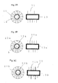
- Fig. 3A is a structural view showing an example of a barrier discharger structure used for NOx decomposition and NO2 generation.
- an insulation electrode portion 13 which is covered by an insulation film such a thin anode oxidization film, the discharger disc plates 11 having discharge portion slits 12 are arranged in a solid structure with suitable spaces.
- the discharger disc plates are connected mutually and electrically.
- the corona discharge When the high frequency and high voltage power supply is applied to between the discharger and the insulation electrode, the corona discharge generates from the outer periphery of the discharger disc plate 11 and an end face of the discharge slit 12. When NOx gas contacts to these discharge portions, the decomposition and the chemical reaction generate.
- the condition of the discharge varies in accordance with a stretching length of the discharge end face, the thickness of the insulation materials of the insulation electrode and the voltage and the frequency number of the high frequency and high voltage power supply to be applied.
- a stretching length of the discharge end face is 500 mm, a good data having the high discharge decomposition efficiency is attained.
- the leakage between the electrodes due to the dirty of the particle shape substance is lessened, and further to arise the durability performance a thin insulation film is performed on a part or a whole of an inner portion of an inside portion of the disc plate.
- the durability performance against to the dirty of the particle shape substance, etc. can be heightened remarkably.
- Fig. 3B shows an example in which, in a discharger disc plate of the discharge element, a slit b is formed on a part of this disc plate and the discharger disc plate 11 a is formed, further on an outer periphery of an insulation electrode portion 13a the discharger disc plate 11a is arranged with a spiral form.
- the flow resistance of the exhaust gas is lessened and at the same time the exhaust gas is contacted easily with the corona, which is generated in an end portion of the discharger, and accordingly the reaction efficiency is improved.
- the discharger electrodes 11a are connected mutually and electrically.
- Fig. 3C shows an example in which to improve the anti -pollution performance of the particle shape substance stated on Fig. 3A the insulation plates 11 b are arranged to the discharger disc plate 11 every one by one.
- a reference numeral 12b denotes the slit 13
- a reference numeral 13b denotes the insulation electrode portion.
- Fig. 4A shows the barrier discharge portion which is the same to the Fig. 3A.
- Fig. 4B shows an example in which the insulation film is formed with a lamination layer using a thin insulation film insulation bodies 14a and 14b, which are processed on an insulation substance of the insulation electrode portion 13C shown in Fig. 4A, by the anode oxidization film etc. and the necessary electric insulation withstanding force is given.
- Fig. 4C shows an example of the discharger d isc plate 11c in which, on a surface of the discharge disc plate 11 shown in Fig. 4A, to give the anti-environment performance against the heat, the oxidation and the arc, to the metal base material such as alumina and titanium the anode oxidation film is performed directly or on a surface of the iron or the chrome steel a thin film such as titanium is carried out the cladding and the surface thereof is carried out the oxidation processing and is finished.
- a reference numeral 12c denotes a discharge slit, which is provided on the discharger disc plate 11.
- Fig. 5A and Fig. 5B will be explained.
- Fig. 5A shows the barrier discharger which is the same to one shown in Fig. 3A.
- Fig. 5B shows an example in which to promote the anti -environment performance the insulation electrode portion 13c and the insulation film 14 shown in Fig. 4B and the discharger disc plate 11 shown in Fig. 4C in which the insulation covering film is performed are combined and more anti -environment performance is promoted.
- a reference numeral 11d denotes a discharger disc plate and a reference numeral 14b denotes an insulation body having the thin insulation film, which is processed by the anode oxidation film etc.
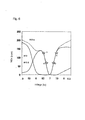
- Fig. 6 shows one example of the characteristic of NOx decomposition in the barrier processing unit against the alternating current application voltage.
- NO reduces abruptly in company with the voltage arise and vanish completely in 6 kV and continues zero (0) until 7.5 kV and further when the voltage arises the concentration increases gradually.
- NOx presents only NO 2 condition and between from 6.5 kV to 7.5 kV, it changes abruptly with V shape between from 130 ppm to zero (0). Accordingly, utilizing this characteristic, it attains the complete processing of the NO and shows the possibility about the decomposition of the particle shape substance without the residual NOx.
- the above stated exhaust gas processing apparatus has the comparative simple structure in comparison with that of the prior art apparatus and has the epoch-making gas processing technique which enable to make the harmless performance of the harmful exhaust gas by following the operation conditions of the engine etc. and utilizes all fields relating to the decomposition of the gas and the reaction.
- This apparatus utilizes effectively to the pollution countermeasurement of the automobiles, the boilers and the engines and the chemical reaction promotion, the combustion promotion, and the decomposition of the harmful substances. Further, the discharge portion can manufactures from the advanced production techniques of the wire and the optical fiber and accordingly the ozone generation apparatus having the high quality, the superior production performance, and the simple structure and the low cost or the corona generating apparatus can provide.
- the particle shape substance can be caught stably, and to the response to the demand the particle shape substance is processed completely using the bug filter and the electric dust collection.
- the effects according to the present invention has the excellent effects as the exhaust gas post-processing apparatus such as the automobiles and the boilers the performance, the cost performance and the maintenance performance can be solved at a stroke.
- the main effects are as following:
Landscapes
- Engineering & Computer Science (AREA)
- Chemical & Material Sciences (AREA)
- Combustion & Propulsion (AREA)
- Mechanical Engineering (AREA)
- General Engineering & Computer Science (AREA)
- Chemical Kinetics & Catalysis (AREA)
- Oil, Petroleum & Natural Gas (AREA)
- Analytical Chemistry (AREA)
- General Chemical & Material Sciences (AREA)
- Health & Medical Sciences (AREA)
- Toxicology (AREA)
- Biomedical Technology (AREA)
- Environmental & Geological Engineering (AREA)
- Processes For Solid Components From Exhaust (AREA)
- Exhaust Gas After Treatment (AREA)
- Electrostatic Separation (AREA)
- Physical Or Chemical Processes And Apparatus (AREA)
Applications Claiming Priority (2)
| Application Number | Priority Date | Filing Date | Title |
|---|---|---|---|
| JP2002184759A JP2004027949A (ja) | 2002-06-25 | 2002-06-25 | 高効率排気ガス処理システム |
| JP2002184759 | 2002-06-25 |
Publications (2)
| Publication Number | Publication Date |
|---|---|
| EP1375850A2 true EP1375850A2 (fr) | 2004-01-02 |
| EP1375850A3 EP1375850A3 (fr) | 2006-05-03 |
Family
ID=29717587
Family Applications (1)
| Application Number | Title | Priority Date | Filing Date |
|---|---|---|---|
| EP03253961A Withdrawn EP1375850A3 (fr) | 2002-06-25 | 2003-06-24 | Système de traitement de gaz d'échappement |
Country Status (4)
| Country | Link |
|---|---|
| US (1) | US6886328B2 (fr) |
| EP (1) | EP1375850A3 (fr) |
| JP (1) | JP2004027949A (fr) |
| KR (1) | KR100996671B1 (fr) |
Cited By (5)
| Publication number | Priority date | Publication date | Assignee | Title |
|---|---|---|---|---|
| FR2891006A1 (fr) * | 2005-09-22 | 2007-03-23 | Renault Sas | Dispositif pour le filtrage et l'elimination des particules contenues dans les gaz d'echappement ameliorant la capture des particules |
| WO2013093536A1 (fr) * | 2011-12-20 | 2013-06-27 | Moanda Antoine Marie-Romain | Absorbeur isolateur de gaz toxiques et procede de neutralisation instantanee |
| RU169412U1 (ru) * | 2015-02-02 | 2017-03-16 | Федеральное государственное бюджетное образовательное учреждение высшего профессионального образования "Кубанский государственный аграрный университет" | Дегазирующее устройство для обработки воздушных сред |
| CN107349737A (zh) * | 2017-09-04 | 2017-11-17 | 南京大学 | 一种高温烟气湿法除尘净化的装置 |
| WO2020083213A1 (fr) * | 2018-10-22 | 2020-04-30 | 上海必修福企业管理有限公司 | Système et procédé de traitement de gaz résiduaire de moteur |
Families Citing this family (7)
| Publication number | Priority date | Publication date | Assignee | Title |
|---|---|---|---|---|
| KR100578467B1 (ko) | 2005-04-02 | 2006-05-10 | 한국기계연구원 | 코아 원심분리 및 정전 농축을 이용한 매연 저감장치 및이를 이용한 저감방법 |
| PT103727A (pt) * | 2007-04-30 | 2008-10-30 | Romualdo Luis Ribera Salcedo | Processo de recirculação electrostática para despoeiramento e lavagem de gases e respectivo dispositivo |
| DE102011115228A1 (de) * | 2011-09-28 | 2013-03-28 | Emitec Gesellschaft Für Emissionstechnologie Mbh | Halterung mit mindestens einer Elektrode |
| JP5970878B2 (ja) * | 2012-03-14 | 2016-08-17 | 富士電機株式会社 | 舶用ディーゼルエンジン排ガス処理装置 |
| EA032168B1 (ru) | 2013-08-09 | 2019-04-30 | Вир Минералс Австралия Лтд | Устройство циклонного сепаратора и способ его производства |
| KR102050262B1 (ko) * | 2018-06-20 | 2020-01-08 | 한국에너지기술연구원 | 고효율 유가 입자 회수장치 |
| CN110170378B (zh) * | 2019-04-11 | 2020-10-16 | 华北水利水电大学 | 一种湿式电除尘雾霾防治系统和使用方法 |
Citations (2)
| Publication number | Priority date | Publication date | Assignee | Title |
|---|---|---|---|---|
| GB1396839A (en) | 1972-06-10 | 1975-06-04 | Aoi K | Process and apparatus for removing nitrogen oxides from waste gas |
| US5458850A (en) | 1993-06-10 | 1995-10-17 | Daimler-Benz Aktiengesellschaft | Method and apparatus for reducing exhaust gases particles |
Family Cites Families (11)
| Publication number | Priority date | Publication date | Assignee | Title |
|---|---|---|---|---|
| CH361074A (de) * | 1958-09-15 | 1962-03-31 | G A Messen Jaschin Fa | Verfahren und Einrichtung zur Reinigung eines Heissgasstromes |
| US4345431A (en) * | 1980-03-25 | 1982-08-24 | Shimizu Construction Co. Ltd. | Exhaust gas cleaning system for diesel engines |
| JPS5788213A (en) * | 1980-11-21 | 1982-06-02 | Nippon Soken Inc | Carbon particle purifying device |
| JPS5958111A (ja) * | 1982-09-25 | 1984-04-03 | Fuji Electric Corp Res & Dev Ltd | デイ−ゼルエンジン用集じん器の二次処理装置 |
| DE3424196A1 (de) * | 1984-02-11 | 1985-08-22 | Robert Bosch Gmbh, 7000 Stuttgart | Einrichtung zur entfernung von festkoerperteilen aus abgasen von brennkraftmaschinen |
| DE3504299A1 (de) * | 1985-02-08 | 1986-08-14 | Robert Bosch Gmbh, 7000 Stuttgart | Vorrichtung zum verbrennen von aus dem abgas von brennkraftmaschinen abgetrennten festkoerperpartikeln, insbesondere russteilchen |
| DE3841182A1 (de) * | 1988-12-07 | 1990-06-13 | Bosch Gmbh Robert | Einrichtung zum entfernen von festkoerperpartikeln, insbesondere russteilchen, aus dem abgas von brennkraftmaschinen |
| US5253476A (en) * | 1992-02-21 | 1993-10-19 | Northeastern University | Pulsed, reverse-flow, regenerated diesel trap capturing soot, ash and PAH's |
| DE4223277C2 (de) * | 1992-07-15 | 2001-07-19 | Linde Ag | Verfahren und Vorrichtung zur Partikelentfernung aus Abgasen von Brennkraftmaschinen |
| DE19515649A1 (de) * | 1995-04-28 | 1995-10-05 | Wilhelm Dr Ing Wiederhold | Filteraggregat zur Reinigung staub- bzw. aerosolhaltiger Gase |
| SE9801567D0 (sv) * | 1998-05-04 | 1998-05-04 | Alfa Laval Ab | Sätt och anläggning för rening av gaser från en förbränningsmotor |
-
2002
- 2002-06-25 JP JP2002184759A patent/JP2004027949A/ja active Pending
-
2003
- 2003-06-24 KR KR1020030041157A patent/KR100996671B1/ko not_active Expired - Fee Related
- 2003-06-24 EP EP03253961A patent/EP1375850A3/fr not_active Withdrawn
- 2003-06-24 US US10/601,628 patent/US6886328B2/en not_active Expired - Fee Related
Patent Citations (2)
| Publication number | Priority date | Publication date | Assignee | Title |
|---|---|---|---|---|
| GB1396839A (en) | 1972-06-10 | 1975-06-04 | Aoi K | Process and apparatus for removing nitrogen oxides from waste gas |
| US5458850A (en) | 1993-06-10 | 1995-10-17 | Daimler-Benz Aktiengesellschaft | Method and apparatus for reducing exhaust gases particles |
Cited By (6)
| Publication number | Priority date | Publication date | Assignee | Title |
|---|---|---|---|---|
| FR2891006A1 (fr) * | 2005-09-22 | 2007-03-23 | Renault Sas | Dispositif pour le filtrage et l'elimination des particules contenues dans les gaz d'echappement ameliorant la capture des particules |
| WO2013093536A1 (fr) * | 2011-12-20 | 2013-06-27 | Moanda Antoine Marie-Romain | Absorbeur isolateur de gaz toxiques et procede de neutralisation instantanee |
| RU169412U1 (ru) * | 2015-02-02 | 2017-03-16 | Федеральное государственное бюджетное образовательное учреждение высшего профессионального образования "Кубанский государственный аграрный университет" | Дегазирующее устройство для обработки воздушных сред |
| CN107349737A (zh) * | 2017-09-04 | 2017-11-17 | 南京大学 | 一种高温烟气湿法除尘净化的装置 |
| WO2020083213A1 (fr) * | 2018-10-22 | 2020-04-30 | 上海必修福企业管理有限公司 | Système et procédé de traitement de gaz résiduaire de moteur |
| WO2020083234A1 (fr) * | 2018-10-22 | 2020-04-30 | 上海必修福企业管理有限公司 | Procédé et système de traitement de gaz d'échappement de moteur |
Also Published As
| Publication number | Publication date |
|---|---|
| KR20040002667A (ko) | 2004-01-07 |
| EP1375850A3 (fr) | 2006-05-03 |
| US6886328B2 (en) | 2005-05-03 |
| KR100996671B1 (ko) | 2010-11-25 |
| JP2004027949A (ja) | 2004-01-29 |
| US20040055286A1 (en) | 2004-03-25 |
Similar Documents
| Publication | Publication Date | Title |
|---|---|---|
| KR101114167B1 (ko) | 배기 가스 정화용 촉매의 재생 장치 및 재생 방법 | |
| US7442218B2 (en) | Exhaust gas treatment apparatus | |
| EP1412060B1 (fr) | Moteur a essence avec systeme d'echappement a combustion des particules | |
| US7510600B2 (en) | Gas purifying apparatus | |
| Okubo et al. | Low-temperature soot incineration of diesel particulate filter using remote nonthermal plasma induced by a pulsed barrier discharge | |
| JPWO2008062554A1 (ja) | ガス浄化装置、ガス浄化システムおよびガス浄化方法 | |
| US6886328B2 (en) | Exhaust gas processing system | |
| WO2001092694A1 (fr) | Appareil pour eliminer la suie et nox des gaz d'echappement de moteurs diesel | |
| CN101542080A (zh) | 气体净化装置、气体净化系统以及气体净化方法 | |
| Shimizu et al. | Effect of water vapor and hydrocarbons in removing NO/sub x/by using nonthermal plasma and catalyst | |
| JP4292511B2 (ja) | 排ガス浄化装置 | |
| US6908596B2 (en) | Exhaust gas processing system | |
| JP6242059B2 (ja) | 放電プラズマリアクタ | |
| Yamamoto et al. | PM and $\hbox {NO} _ {\rm x} $ Removal for Diesel Engine Emission Using Ozonizer and Chemical Hybrid Reactor | |
| JP2004204739A (ja) | 排ガス浄化システムおよび排ガス浄化方法 | |
| Okubo et al. | Soot incineration of diesel particulate filter using honeycomb nonthermal plasma | |
| HK1063067A (en) | Exhaust gas processing system | |
| JP4591164B2 (ja) | 排ガス浄化方法及び排ガス浄化装置 | |
| WO2004109071A1 (fr) | Purificateur de gaz d'echappement | |
| JP2004092589A (ja) | 内燃機関の排ガス浄化装置 | |
| JP2001349215A (ja) | Noxを吸着材に付着させて分解する排気ガス浄化装置 | |
| JP2006026483A (ja) | 排ガス浄化装置 | |
| CN214416363U (zh) | 一种用于处理气态介质的等离子体反应器 | |
| JP2004216201A (ja) | 燃焼排気黒煙、不完全燃焼物およびnoxの除去方法および装置 | |
| KR100404417B1 (ko) | 디젤엔진 배출가스에서 매연과 질소산화물을 제거하기위한 디젤분진필터/플라즈마/촉매 시스템 |
Legal Events
| Date | Code | Title | Description |
|---|---|---|---|
| PUAI | Public reference made under article 153(3) epc to a published international application that has entered the european phase |
Free format text: ORIGINAL CODE: 0009012 |
|
| AK | Designated contracting states |
Kind code of ref document: A2 Designated state(s): AT BE BG CH CY CZ DE DK EE ES FI FR GB GR HU IE IT LI LU MC NL PT RO SE SI SK TR |
|
| AX | Request for extension of the european patent |
Extension state: AL LT LV MK |
|
| REG | Reference to a national code |
Ref country code: HK Ref legal event code: DE Ref document number: 1063067 Country of ref document: HK |
|
| PUAL | Search report despatched |
Free format text: ORIGINAL CODE: 0009013 |
|
| AK | Designated contracting states |
Kind code of ref document: A3 Designated state(s): AT BE BG CH CY CZ DE DK EE ES FI FR GB GR HU IE IT LI LU MC NL PT RO SE SI SK TR |
|
| AX | Request for extension of the european patent |
Extension state: AL LT LV MK |
|
| RIC1 | Information provided on ipc code assigned before grant |
Ipc: F01N 3/08 20060101ALI20060316BHEP Ipc: B01D 45/16 20060101ALI20060316BHEP Ipc: B01D 53/32 20060101ALI20060316BHEP Ipc: B01D 53/94 20060101ALI20060316BHEP Ipc: F01N 3/20 20060101ALI20060316BHEP Ipc: F01N 3/01 20060101ALI20060316BHEP Ipc: F01N 3/037 20060101AFI20030813BHEP |
|
| 17P | Request for examination filed |
Effective date: 20061030 |
|
| AKX | Designation fees paid |
Designated state(s): DE FR GB |
|
| 17Q | First examination report despatched |
Effective date: 20061221 |
|
| GRAP | Despatch of communication of intention to grant a patent |
Free format text: ORIGINAL CODE: EPIDOSNIGR1 |
|
| STAA | Information on the status of an ep patent application or granted ep patent |
Free format text: STATUS: THE APPLICATION IS DEEMED TO BE WITHDRAWN |
|
| 18D | Application deemed to be withdrawn |
Effective date: 20091027 |
|
| REG | Reference to a national code |
Ref country code: HK Ref legal event code: WD Ref document number: 1063067 Country of ref document: HK |