EP1375979A2 - Elektrisches Leistungsversorgungssystem, Kennwertermittlungs- und Diagnosesystem und Diagnoseverfahren - Google Patents
Elektrisches Leistungsversorgungssystem, Kennwertermittlungs- und Diagnosesystem und Diagnoseverfahren Download PDFInfo
- Publication number
- EP1375979A2 EP1375979A2 EP03014125A EP03014125A EP1375979A2 EP 1375979 A2 EP1375979 A2 EP 1375979A2 EP 03014125 A EP03014125 A EP 03014125A EP 03014125 A EP03014125 A EP 03014125A EP 1375979 A2 EP1375979 A2 EP 1375979A2
- Authority
- EP
- European Patent Office
- Prior art keywords
- line
- ground return
- return line
- characteristic value
- value determination
- Prior art date
- Legal status (The legal status is an assumption and is not a legal conclusion. Google has not performed a legal analysis and makes no representation as to the accuracy of the status listed.)
- Granted
Links
Images

Classifications
-
- G—PHYSICS
- G05—CONTROLLING; REGULATING
- G05B—CONTROL OR REGULATING SYSTEMS IN GENERAL; FUNCTIONAL ELEMENTS OF SUCH SYSTEMS; MONITORING OR TESTING ARRANGEMENTS FOR SUCH SYSTEMS OR ELEMENTS
- G05B23/00—Testing or monitoring of control systems or parts thereof
- G05B23/02—Electric testing or monitoring
- G05B23/0205—Electric testing or monitoring by means of a monitoring system capable of detecting and responding to faults
- G05B23/0218—Electric testing or monitoring by means of a monitoring system capable of detecting and responding to faults characterised by the fault detection method dealing with either existing or incipient faults
- G05B23/0224—Process history based detection method, e.g. whereby history implies the availability of large amounts of data
- G05B23/0227—Qualitative history assessment, whereby the type of data acted upon, e.g. waveforms, images or patterns, is not relevant, e.g. rule based assessment; if-then decisions
- G05B23/0235—Qualitative history assessment, whereby the type of data acted upon, e.g. waveforms, images or patterns, is not relevant, e.g. rule based assessment; if-then decisions based on a comparison with predetermined threshold or range, e.g. "classical methods", carried out during normal operation; threshold adaptation or choice; when or how to compare with the threshold
-
- G—PHYSICS
- G01—MEASURING; TESTING
- G01R—MEASURING ELECTRIC VARIABLES; MEASURING MAGNETIC VARIABLES
- G01R31/00—Arrangements for testing electric properties; Arrangements for locating electric faults; Arrangements for electrical testing characterised by what is being tested not provided for elsewhere
- G01R31/40—Testing power supplies
-
- F—MECHANICAL ENGINEERING; LIGHTING; HEATING; WEAPONS; BLASTING
- F16—ENGINEERING ELEMENTS AND UNITS; GENERAL MEASURES FOR PRODUCING AND MAINTAINING EFFECTIVE FUNCTIONING OF MACHINES OR INSTALLATIONS; THERMAL INSULATION IN GENERAL
- F16H—GEARING
- F16H61/00—Control functions within control units of change-speed- or reversing-gearings for conveying rotary motion ; Control of exclusively fluid gearing, friction gearing, gearings with endless flexible members or other particular types of gearing
- F16H61/12—Detecting malfunction or potential malfunction, e.g. fail safe ; Circumventing or fixing failures
- F16H2061/1208—Detecting malfunction or potential malfunction, e.g. fail safe ; Circumventing or fixing failures with diagnostic check cycles; Monitoring of failures
-
- H—ELECTRICITY
- H02—GENERATION; CONVERSION OR DISTRIBUTION OF ELECTRIC POWER
- H02J—ELECTRIC POWER NETWORKS; CIRCUIT ARRANGEMENTS OR SYSTEMS FOR SUPPLYING OR DISTRIBUTING ELECTRIC POWER; SYSTEMS FOR STORING ELECTRIC ENERGY
- H02J3/00—Circuit arrangements for AC mains or AC distribution networks
Definitions
- the invention relates to an electrical power supply system Characteristic determination system and a diagnostic system and method for a electrical power supply system for actuators in Drive units, especially of electromagnetic actuators in Transmission units.
- the document DE 197 45 175 A1 discloses a diagnostic device and a Diagnostic method for electromagnetic transmissions associated with an automatic transmission Parking facilities.
- the actuators are shared Supply line connected to a power supply.
- a measuring resistor with a differential amplifier to determine the Total current arranged which with the input of a control device, in particular a microcomputer is coupled.
- everyone will Actuator supplied currents determined individually and their sum with the Total current compared.
- An error can be identified from a deviation, which to start an emergency program with the locking of certain gears or Checking the faulty current path and compensating for the deviation by adapting the control of a circuit breaker.
- the document DE 41 34 056 A1 discloses a current control circuit for a electromagnetic proportional actuator.
- a specially designed Short-circuit safety circuit protects the current control circuit against unintentional incorrect connections as well as short circuits.
- a disadvantage of the known solutions is that they make a statement about errors in the power transmission according to the concrete Installation situation can only take place on the basis of a large number of current actual values, their determination requires a corresponding effort.
- a separate Checking individual line connections to the control devices is possible with the Execution according to the first mentioned publication is not possible directly.
- the invention is therefore based on the object of a method for diagnosis and to create a diagnostic and characteristic value determination device, by means of which regardless of the installation situation of power supply and Actuators very simple and with little effort an objective statement about the power supply of a single control device, in particular their wiring and that required at the voltage source minimum voltage to be provided can be met. Also should impermissible earth connections can be recognized safely and quickly.
- the diagnostic method according to the invention for the electrical Power supply for in drive units, especially gearboxes arranged electromagnetic actuating devices takes place for Circuit arrangements according to the invention electrical Power supply systems with a voltage supply, one each, a supply line assigned to an actuating device and one to all Common ground return actuators.
- the Actuators at a distance from the power supply arranged.
- the control of the control devices takes place via a Control device. This serves to act upon an actuating device an assigned supply line that is spatially removed with a arranged voltage supply is coupled. All actuators are a common ground return is assigned.
- the determined during an initial determination Values for the line resistances in the supply lines and the Ground return for diagnostic purposes are saved as reference values and each with a time interval determined values for the line resistances are compared. at If the reference value is exceeded, an error information is displayed under Taking tolerances into account.
- the information regarding the line cross-sections is usually by standardized sizes, which are used when installing the adjusting devices of the Switching elements and their electrical power supply system in one of the Gear unit assigned control or a higher-level Control device can be stored or can be selected.
- the method according to the invention offers the advantage of being relatively simple Circuit arrangement regardless of the specific installation situation, especially the distance between actuator and power supply and detection and / or diagnostic device with little effort on the sizes due to the installation situation, especially the Line resistance and the line length used to close and this as To use the basis for error detection because of a strong change of the resistance value, an error can be concluded, in particular a defect in the wiring. Furthermore, this method can Initial commissioning in an advantageous manner, the functionality check serve.
- At least one switch is provided in the ground return line, which is designed in such a way that an inadmissible earth connection with, for example, a housing or another element or the vehicle mass can be recognized in the open state and when the actuating devices are energized when a current flows.
- the switch can be, for example, a semiconductor switch or a relay.
- the switch can be arranged in the control direction of the characteristic value determination system or outside.
- the invention Procedure taking into account all actuating devices operated simultaneously Determination of the required total voltage from the drop over the Ground return lines can be used.
- the minimum actuation voltage which is to be provided for an actuating device results from the Voltage drop across the associated supply line Minimum current, the minimum functional voltage of the control device, i.e. the Voltage drop across the actuator, and the voltage drop across the Ground return.
- Minimum current the minimum functional voltage of the control device, i.e. the Voltage drop across the actuator
- the voltage drop across the Ground return is the number of simultaneously operated Actuators dependent. This provision can apply in particular to Initial commissioning of fixing or review of the manufacturers for the individual aggregates serve the minimum functional voltages required for the function of the individual control device are required.
- the after Initial commissioning determined line resistance before comparison with the Reference value always around a correction value, which shows the resistance behavior reflected at different temperatures, corrected.
- the correction value can take into account at least one, the current temperature at least indirectly descriptive size in the vicinity of the lines be calculated or is only estimated. In the latter case, too a correction value can be specified, which is a possible range limit.
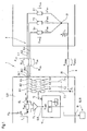
- FIG. 1 illustrates in a schematically simplified representation the basic structure of a diagnostic and / or characteristic value determining device 1 designed according to the invention for the electrical power supply of electromagnetic actuating devices 2.1 to 2.n, in the case 2.1, 2.2 and 2.n shown, for example in the form of magnetic coils as electromagnetic Actuators for realizing a gear stage change in a gear unit 20.
- electromagnetic actuating devices 2.1 to 2.n these are energized by means of an assigned control device 3, comprising at least one microcomputer 21, depending on the desired gear stage to be engaged.
- the circuit arrangement 4 for coupling the individual actuating devices 2.1 to 2.n to a voltage supply source 22 provided for this purpose is as follows:
- the individual electromagnetic actuating devices 2.1 to 2.n are via a supply line 5.1 to 5 assigned to each actuating device 2.1 to 2.n.
- n can be connected to a voltage supply 22 for providing the supply voltage U B via T 1 to T n , only T1 being shown for reasons of clarity.
- the control device 3 is generally designed as a control device and is arranged at a spatial distance from the gear unit 20.
- Each electromagnetic actuator 2.1 to 2.n is assigned its own supply line 5.1 to 5.3.
- the control device 3 comprises n outputs 24.1 to 24.n, which are coupled to the actuating devices 2.1 to 2.n via the supply lines 5.1 to 5.n.
- the electromagnetic actuating devices 2.1 to 2.3 have a common ground return line 6, which is coupled to an input 25.
- the individual supply lines 5.1 to 5.n of the actuating devices 2.1 to 2.n are brought together in the current flow direction behind the actuating devices 2.1 to 2.n in a node 23 to which the ground return line 6 is coupled in the transmission.
- Each supply line 5.1 to 5.n is coupled to the ground return line 6 in close proximity to the electronic control unit 3 or preferably in it via a connecting line 7.1 to 7.n - shown here only 7.1 - in which means 8.1 to 8.n for detection in each case at least one variable that at least indirectly characterizes the voltage drop U n between the supply line 5.n and the ground return line 6.
- These means are generally formed by measuring resistors 9, via which the voltage drop U 1 , U 2 or U n is determined when the current I MV1 , I MV2 or I MVn flowing through the respective electromagnetic actuating device 2.1, 2.2 or 2.n is known can be.
- Each supply line 5.1 to 5.n also contains a measuring resistor 10 1-n with a differential amplifier 11 1-n assigned to it for determining the current I MVn .
- FIG. 1 shows only the measuring resistor and differential amplifier for the first supply line 5.1.
- the voltage drop U 1 - U 3 or U n by means of the voltage divider 8.1 / 9.1 does not represent the voltage actually effective at the electromagnetic actuating devices 2.n, but also contains the voltage drop across the ground return line 6 U LMass and the voltage drop across the actuating device 2.n assigned supply line 5.n U LVn , here for example U LV1 of the supply line 5.1.
- the voltage drop U LMasse in the ground return line 6 results from the product of the sum of the currents I MV1 to I MVn through the electromagnetic actuating devices 2.1 to 2.n and the line resistance R LMasse .
- a defined minimum current and / or a defined minimum functional voltage is required for the safe operation of the electromagnetic actuators 2.1 to 2.n, or a minimum operating voltage U MVn at the electromagnetic actuators 2.n resulting from the minimum current under assumed extreme conditions. It is known that the supply voltage U B can fluctuate greatly when used in vehicles due to the load on the vehicle electrical system. The vehicle manufacturers thus specify certain minimum voltages U B , up to which the individual control devices and actuators, ie the control device 3 and electromagnetic actuating devices 2.1 to 2.n, must guarantee their function.
- the voltage drop U LMasse in the ground return line 6 is first determined according to the invention.
- at least one first electromagnetic actuating device for example 2.1, is not energized in a first method step in the circuit arrangement 4 described, while at least one further second or also several actuating devices, here for example 2.2 and 2.n, are energized.
- the sum of the currents is fed to further inputs 13.1 ... 13.n.
- the length I mass can then be calculated as a function of the cross section A.
- the information on the conductor cross section A can either already be stored in the control device 3 or can be called up from another data source or can be entered.
- the calculation can also be done in a connected for this purpose Diagnostic system setup (PC ).
- the line resistance R LVn and the voltage drop across the supply line U LVn can be calculated with a known line cross section A of the supply lines. From the statements about the length of the individual lines - supply line 5.1 to 5.n or ground return line 6, the functional area of the transmission control together with the individual actuators, ie electromagnetic actuating devices 2.1 to 2.n, can be determined in relation to the operating voltage U to be provided at the voltage source 22 B-be specified at least . This information, at least about the individual resistances - line resistance R LMasse and R LVn - is determined during commissioning or initial acceptance tests when used in vehicles to control the function of the overall system and its reliability. This information is preferably output via a display device 15 and is also stored in a storage unit 16.
- the diagnostic method according to the invention is designed as illustrated in FIG. 2 using a signal flow diagram.
- one of the electromagnetic actuators 2.1 to 2.n for example 2.1, is kept free of current, while at least one of the others, preferably a plurality of the electromagnetic actuators 2.2 to 2.n, is kept with it be supplied with a current I MV2 to I MVN .
- the voltage drop U 1 between the supply line 2.1 and the ground return line 6 is determined.
- the resistance in the feed line R LV1 can be determined as a function of the length I V1 and the cross section A V1 .
- the determined resistance values for the ground return line 6 and the individual supply lines 5.1 to 5.n are determined again at specific time intervals and compared with the values determined during the first determination. For this purpose, these are stored as a comparison variable in a storage device or, for example, also on other information carriers via a data communication network.
- the newly determined resistance values are adjusted with regard to the temperature dependency, ie either multiplied by a corresponding factor or subjected to another mathematical operation.
- the respective line or its connections diagnoses an error and can for example in the form of an optically recognizable signal.
- the driver can then decide whether to interrupt the driving process or not. In the other case, the gear step through can already be done without the driver's intervention the actuation of the corresponding control devices is characterized, blocked become.
- These process steps carried out up to the determination of the minimum voltage U B-minimum can be integrated on the one hand in a method for providing a minimum voltage U B-minimum and preventing it from being undershot, this minimum voltage value U B-at least preferably when starting up or starting up the vehicle for the first time is determined and stored in a memory.
- the currently available supply voltage U B-currently in an on-board electrical system is continuously compared with the minimum voltage U B-at least , with no reaction if exceeded, while a command value for providing the required minimum voltage U B-at least is emitted when it is undershot, for example can be done by controlling an energy source or switching off other consumers.
- a switch S 1 in the circuit arrangement described in FIG. 1 between the ground return line 6 and the connecting line between the supply line and the ground return line with which a check for an impermissible ground connection can be carried out by opening the switch S 1 a current is sent via one of the actuators 2.1 to 2.n. A current will only flow if there is an impermissible ground connection, otherwise no current can be determined.
- the entirety of voltage source 22, supply lines and Ground return forms an electrical power supply system 25; this combined with the control unit without storage device and The diagnostic system forms a comparison device for earlier values. to A memory and a comparison device are not determination of characteristic values absolutely necessary.
Landscapes
- Physics & Mathematics (AREA)
- General Physics & Mathematics (AREA)
- Engineering & Computer Science (AREA)
- Automation & Control Theory (AREA)
- Testing Of Short-Circuits, Discontinuities, Leakage, Or Incorrect Line Connections (AREA)
- Control Of Electric Motors In General (AREA)
- Control Of Transmission Device (AREA)
- Control Of Voltage And Current In General (AREA)
- Testing Electric Properties And Detecting Electric Faults (AREA)
- Emergency Protection Circuit Devices (AREA)
Abstract
Description
- Bestromung wenigstens einer beliebigen ersten Stelleinrichtung bei gleichzeitiger Nicht-Bestromung einer weiteren zweiten, beliebigen Stelleinrichtung;
- Messung des Spannungsabfalles zwischen der Versorgungsleitung der nicht bestromten Stelleinrichtung und der Masserückleitung.
- Summe der Ströme zu den bestromten Stelleinrichtungen;
- Spannungsabfall in der Masserückleitung;
- Leitungswiderstand in der Masserückleitung;
- Länge der Masserückleitung;
- Leitungswiderstand und Spannungsabfall in der Versorgungsleitung. Bei Integration des Kennwertermittlungssystems in einem Diagnosesystem umfaßt dieses einen Speicher zur Speicherung von Referenzwerten und eine Vergleichseinrichtung zum Vergleich aktuell ermittelter Größen mit Referenzwerten. Mit der Vergleichseinrichtung ist ein Stellgrößenbildner für eine Fehlerinformation gekoppelt. Die Funktion des Speichers, der Berechnungs- und Zuordnungseinrichtungen und der Vergleichseinrichtung werden vorzugsweise vom Microcontroller übernommen, so daß diese nicht als separate bauliche Einheiten vorliegen. Der Microcontroller ist in diesem Fall mit den entsprechenden Eingängen der Diagnoseeinrichtung gekoppelt bzw. bildet diese. Gemäß einer besonders vorteilhaften Ausgestaltung in einem Steuer- und Regelsystem für Getriebebaueinheiten werden die Kennwerterfassungseinrichtung und Diagnoseeinrichtung vom Getriebesteuergerät bzw. dem Gerät eines diesem übergeordneten Steuersystems gebildet, d.h. die Funktion der Diagnose wird von einem ohnehin vorhandenen System mit übernommen.
- Figur 1
- verdeutlicht in schematisch vereinfachter Darstellung den Grundaufbau eines erfindungsgemäß gestalteten Diagnosesystems;
- Figur 2
- verdeutlicht anhand eines Signalflußbildes den Ablauf des erfindungsgemäßen Verfahrens.
- Un -
- Spannungsabfall zwischen Versorgungsleitung 5.n und Masserückleitung 6 bzw. Ausgang 24.n und Eingang 6
- UMVn
- Spannungsabfall über der elektromagnetischen Stelleinrichtung 2.n
- ULVn
- Spannungsabfall in der Versorgungsleitung 5.n zur Versorgung des elektromagnetischen Stellgliedes 2.n
- ULMasse -
- Spannungsabfall in der Masserückleitung 6.
Zur Bestimmung dessen wird in einem ersten Verfahrensschritt bei der beschriebenen Schaltungsanordnung 4 wenigstens eine erste elektromagnetische Stelleinrichtung, beispielsweise 2.1, nicht bestromt, während wenigstens eine weitere zweite oder auch mehrere Stelleinrichtungen, hier beispielsweise 2.2 und 2.n, bestromt werden. Entsprechend dem Maschensatz ergibt sich aus der obengenannten Beziehung für den Spannungsabfall U1 zwischen der Versorgungsleitung 5.1 und der Masserückleitung 6 aufgrund der Nichtbestromung folgende Beziehung U1 = ULMasse.
- IMVn -
- Strom über das elektromagnetische Stellglied 2.n.
- Anzeige mit Hinweis auf Defekt und Aufforderung Werkstatt aufzusuchen
- Anzeige und Sperrung der Gangstufen, die durch die Betätigung der Stelleinrichtungen charakterisiert sind, für welche erhöhte Widerstandswerte ermittelt wurden
- 1
- Diagnosevorrichtung
- 2.1 - 2.n
- elektromagnetische Stelleinrichtungen
- 3
- elektronisches Steuergerät
- 4
- Schaltungsanordnung
- 5.1 - 5.n
- Versorgungsleitung
- 6
- Masserückleitung
- 7.1 - 7.3
- Verbindungsleitung
- 8
- Mittel zur wenigstens mittelbaren Erfassung wenigstens einer den Spannungsabfall wenigstens indirekt charakterisierenden Größe
- 9
- Meßwiderstand
- 10
- Meßwiderstand
- 11
- Differenzverstärker
- 12
- Eingang
- 13
- Eingang
- 14
- Berechnungseinheit
- 15
- Anzeigevorrichtung
- 16
- Speichereinheit
- 17
- Vergleichseinrichtung
- 18
- Ausgang
- 19
- Display
- 20
- Getriebebaueinheit
- 21
- Microrechner
- 22
- Spannungsversorgungsquelle
- 23
- Knoten
- 24.1 - 24.n
- Ausgang
- 25
- Leistungsversorgungssystem
- 26
- Kennwertermittlungssystem
- UB
- Versorgungsspannung
- UBmindest
- Mindestversorgungsspannung
- I1 bis In
- Ströme zu den elektromagnetischen Stellgliedern 2.1 bis 2.n
- U1 bis Un
- Spannungsabfall zwischen der Versorgungsleitung 24.1 bis 24.n und der Masserückleitung 6
- ULMasse
- Spannungsabfall über der Masserückleitung
- ULn
- Spannungsabfall über der Versorgungsleitung n
- UMVn
- Spannungsabfall am elektromagnetischen Stellglied n
- RLMasse
- Leitungswiderstand der Masserückleitung
- RLn
- Leitungswiderstand der Versorgungsleitung
- AMasse
- Leiterquerschnitt der Masserückleitung
- ALn
- Leitungsquerschnitt der Versorgungsleitung n
- IMasse
- Länge der Masserückleitung (6)
- ILn
- Länge der Versorgungsleitung
Claims (35)
- Elektrisches Leistungsversorgungssystem (25) für Stelleinrichtungen (2.1-2.n) in Antriebsaggregaten, insbesondere elektromagnetisch betätigbarer Stellglieder einer Getriebebaueinheit (20);
mit einer Schaltungsanordnung (4),
gekennzeichnet durch die folgenden Merkmale:1.1 die Schaltungsanordnung (4) umfaßt Spannungsversorgungsquelle (22);1.2 die Schaltungsanordnung (4) umfaßt eine jeder elektromagnetischen Stelleinrichtung (2.1-2.n) zugeordnete Versorgungsleitung (5.1-5.n), die mit einer Spannungsversorgungsquelle (22) verbindbar ist;1.3 mit einer allen elektromagnetischen Stelleinrichtungen (2.1-2.n) gemeinsam zugeordneten Masserückleitung (6);1.4 mit einem in der Masserückleitung (6) angeordneten Schalter (S1), der derart ausgebildet ist, dass über diesen bei Öffnung und gleichzeitiger Bestromung einer Stelleinrichtung (2.1-2.n) bei Fließen eines Stromes eine unzulässige Masseverbindung erkennbar ist. - Kennwertermittlungssystem (26) für ein elektrisches Leistungsversorgungssystem für Stelleinrichtungen (2.1-2.n) in Antriebsaggregaten, insbesondere elektromagnetisch betätigbarer Stellglieder einer Getriebebaueinheit nach Anspruch 1;2.1 mit einer Kennwertermittlungs- und Bestimmungseinrichtung, umfassend wenigstens einen Microcontroller (21);2.2 mit Mitteln zur Erfassung des Spannungsabfalles zwischen jeweils einer Versorgungsleitung (5.1-5.n) und der Masserückleitung (6);2.3 mit Mitteln zur Erfassung des Stromes in jeder Versorgungsleitung (5.1-5.n);2.4 mit wenigstens einer Berechnungs- und Zuordnungseinrichtung (14) zur Ermittlung der nachfolgend genannten Größen:Summe der Ströme zu den bestromten Stelleinrichtungen (2.1-2.n);Spannungsabfall in der Masserückleitung (6);Leitungswiderstand der Masserückleitung (6);Länge der Masserückleitung (6);Leitungswiderstand und Spannungsabfall in der Versorgungsleitung (5.1-5.n).
- Kennwertermittlungssystem (26) nach Anspruch 2, dadurch gekennzeichnet, daß eine Berechnungs- und Zuordnungeinrichtung (14) zur Ermittlung der erforderlichen bereitzustellenden Mindestbetriebsspannung für jede Stelleinrichtungen (2.1-2.n) vorgesehen ist.
- Kennwertermittlungssystem (26) nach einem der Ansprüche 2 oder 3, dadurch gekennzeichnet, daß die Kennwertermittlungseinrichtung von einer der Getriebebaueinheit zugeordneten Steuereinrichtung (3) gebildet wird.
- Kennwertermittlungssystem (26) nach einem der Ansprüche 2 bis 4, dadurch gekennzeichnet, daß jede Versorgungsleitung (5.1-2.n) mit einem eigenen Eingang der Kennwerterfassung- und Bestimmungseinrichtung gekoppelt ist.
- Kennwertermittlungssystem (26) nach Anspruch 5, dadurch gekennzeichnet, daß die Mittel zur Erfassung des Stromes in jeder Versorgungsleitung (5.1-5.n) in der Kennwertermittlungs- oder Bestimmungseinrichtung integriert sind.
- Kennwertermittlungssystem (26) nach einem der Ansprüche 2 bis 6, dadurch gekennzeichnet, daß die Mittel zur Erfassung des Spannungsabfalles zwischen jeweils einer Versorgungsleitung (5.1-5.n) und der Masserückleitung (6) einen Spannungsteiler (8) umfassen.
- Kennwertermittlungssystem (26) nach einem der Ansprüche 2 bis 7, dadurch gekennzeichnet, daß die Mittel zur Erfassung des Spannungsabfalles zwischen jeweils einer Versorgungsleitung (5.1-5.n) und der Masserückleitung (6) mit jeweils einem Eingang der Kennwertermittlungs- oder Bestimmungseinrichtung gekoppelt sind oder diese bilden.
- Kennwertermittlungssystem (26) nach einem der Ansprüche 2 bis 8, dadurch gekennzeichnet, daß die Berechnungs- und Zuordnungseinrichtung (14) einen Summenstrombildner umfaßt.
- Kennwertermittlungssystem (26) nach einem der Ansprüche 2 bis 9, dadurch gekennzeichnet, daß die Berechnungs- und Zuordnungseinrichtung (14) eine Berechnungseinheit zur Berechnung des Widerstandes in der Masserückleitung (6) umfaßt.
- Kennwertermittlungssystem (26) nach einem der Ansprüche 2 bis 10, dadurch gekennzeichnet, daß die Berechnungs- und Zuordnungseinrichtung (14) eine Berechnungseinheit zur Ermittlung der Leistungslänge der Masserückleitung (6) aufweist.
- Kennwertermittlungssystem (26) nach einem der Ansprüche 2 bis 11, dadurch gekennzeichnet, daß die Berechnungs- und Zuordnungseinrichtung eine Zuordnungseinheit der Länge der Versorgungsleitung (5.1-5.n) zur Länge der Masserückleitung (6) aufweist.
- Kennwertermittlungssystem (26) nach einem der Ansprüche 2 bis 9, dadurch gekennzeichnet, daß die Berechnungs- und Zuordnungseinrichtung eine Berechnungseinheit zur Berechnung des Widerstandes in der Versorgungsleitung (5.1-5.n) umfaßt.
- Kennwertermittlungssystem (26) nach einem der Ansprüche 4 bis 9, dadurch gekennzeichnet, daß die Eingänge der Kennwertermittlungs- und Berechnungseinrichtung Eingänge der der Getriebebaueinheit (20) zugeordneten Steuereinrichtung (3) bilden.
- Kennwertermittlungssystem (26) nach einem der Ansprüche 2 bis 14, dadurch gekennzeichnet, daß die Berechnungs- und Zuordnungseinrichtung (14) vom Microrechner (21) gebildet wird.
- Kennwertermittlungssystem (26) nach Anspruch 15, dadurch gekennzeichnet, daß der Speicher (16), die Berechnungs- und Zuordnungseinrichtung (14) und die Vergleichseinrichtung (17) vom Microrechner (21) gebildet werden.
- Diagnosevorrichtung (1) für ein elektrisches Leistungsversorgungssystem (25) für Stelleinrichtungen (2.1-2.n) in Antriebsaggregaten gemäß Anspruch 117.1 mit einem Kennwertermittiungssystem (26) nach einem der Ansprüche 2 bis 16;17.2 die Kennwertermittiungseinrichtung bildet eine Diagnoseeinrichtung;17.3 mit einem Speicher (16) zur Speicherung von Referenzwerten;17.4 mit einer Vergleichseinrichtung (17) zum Vergleich aktuell ermittelter Größen mit Referenzwerten;17.5 mit einem mit der Vergleichseinrichtung (17) gekoppelten Stellgrößenbildner für eine Fehlerinformation.
- Diagnosesystem (1) nach Anspruch 17, dadurch gekennzeichnet, daß der Speicher (16), die Berechnungs- und Zuordnungseinrichtung (14) und die Vergleichseinrichtung (17) vom Microrechner (21) gebildet werden.
- Kennwertermittlungssystem (26) nach einem der Ansprüche 17 oder 18, dadurch gekennzeichnet, daß die Eingänge der Diagnoseeinrichtung vom Microrechner (21) gebildet werden oder mit diesem verbunden sind.
- Diagnoseverfahren für ein elektrisches Leistungsversorgungssystem für Stelleinrichtungen (2.1-2.n) in Antriebsaggregaten, insbesondere elektromagnetischen Stelleinrichtungen (2.1-2.n) in Getriebebaueinheiten (20), mit den folgenden Merkmalen:jede Stelleinrichtung (2.1-2.n) ist über eine dieser zugeordnete Versorgungsleitung (5.1-5.n) mit einer räumlich entfernt angeordneten Spannungsversorgung (22) gekoppelt;allen Stelleinrichtungen (2.1-2.n) ist eine gemeinsame Masserückleitung (6) zugeordnet;20.1 bei welchem in zeitlichem Abstand wenigstens der Spannungsabfall in der Masserückleitung (6) ermittelt wird und aus wenigstens dem Spannungsabfall in der Masserückleitung (6) die Leitungswiderstände der einzelnen Versorgungsleitungen (5.1-5.N) und der Masserückleitung (6) ermittelt werden;20.2 bei welchem die bei einer Erstermittlung ermittelten Werte für die Leitungswiderstände in den Versorgungsleitungen (5.1-5.n) und der Masserückleitung (6) als Referenzwerte gespeichert werden und jeweils mit den in zeitlichem Abstand ermittelten Werten für die Leitungswiderstände verglichen werden, wobei bei Überschreitung des Referenzwertes eine Fehlerinformation abgeleitet wird.
- Verfahren nach Anspruch 1, dadurch gekennzeichnet, daß die Ermittlung des
Spannungsabfalls in der Masserückleitung (6) die folgenden Schritte beinhaltet:21.1 Bestromung wenigstens einer ersten Stelleinrichtung (2.1-2.n) bei gleichzeitiger Nicht-Bestromung wenigstens einer weiteren zweiten Stelleinrichtung (2.1-2.n);21.2 Messung des Spannungsabfalles zwischen der Versorgungsleitung (5.1-5.n) der nicht bestromten Stelleinrichtungen (2.1-2.n) und der Masserückleitung (6). - Verfahren nach Anspruch 21, dadurch gekennzeichnet, daß zur Ermittlung des Leitungswiderstandes die Summe der Ströme zu den Stelleinrichtungen (2.1-2.n), insbesondere der Summenstrom in der Masserückleitung (6) ermittelt wird und der Leitungswiderstand als Funktion aus Spannungsabfall zwischen der Versorgungsleitung (5.1-5.n) der nicht bestromten Stelleinrichtungen (2.1-2.n) und der Masserückleitung (6) und dem Summenstrom ermittelt wird.
- Verfahren nach Anspruch 22, dadurch gekennzeichnet, daß der Spannungsabfall über einer bestromten Versorgungsleitung (5.1-5.n) als Funktion des in der Versorgungsleitung (5.1-5.n) fließenden Einzelstromes und des Widerstandes der Masserückleitung (6) bestimmt wird.
- Verfahren nach Anspruch 23, gekennzeichnet durch die folgenden Merkmale:24.1 bei Kenntnis des Leitungsquerschnittes der Masserückleitung (6) wird aus dem Leitungswiderstand die Länge der Masserückleitung (6) berechnet;24.2 die Länge der Masserückleitung (6) wird unter Berücksichtigung eines vordefinierten Toleranzwertes der Länge der Versorgungsleitung (5.1-5.n) gleichgesetzt;24.3 bei bekanntem Leitungsquerschnitt der Versorgungsleitung (5.1-5.n) wird der Leitungswiderstand der Versorgungsleitung (5.1-5.n) berechnet.
- Verfahren nach Anspruch 24, dadurch gekennzeichnet, daß aus dem Einzelstrom in der Versorgungsleitung (5.1-5.n) und dem Leitungswiderstand der Spannungsabfall über der bestromten Versorgungsleitung (5.1-5.n) berechnet wird.
- Verfahren nach Anspruch 25, dadurch gekennzeichnet, daß die erforderliche Mindestbetätigungspannung einer Stelleinrichtung (2.1-2.n) als Funktion der Summe aus dem Spannungsabfall über dieser einen Versorgungsleitung (5.1-5.n) bei Mindeststrom, dem Spannungsabfall über der Stelleinrichtung (2.1-2.n) und dem Abfall über der Masserückleitung (6) unter Berücksichtigung aller gleichzeitig betätigten Stelleinrichtungen (2.1-2.n) ermittelt wird.
- Verfahren nach einem der Ansprüche 25 oder 26, dadurch gekennzeichnet, daß die an der Spannungsquelle (22) bereitzustellende'erforderliche Mindestspannung als Funktion der Summe aus den einzelnen Mindestbetätigungsspannungen für alle gleichzeitig betätigten Stelleinrichtungen (2.1-2.n) gebildet wird.
- Verfahren nach einem der Ansprüche 20 bis 27, dadurch gekennzeichnet, daß bei Abweichung der jeweiligen Leitungswiderstandswerte vom Referenzwert die Art der Fehlerinformation in Abhängigkeit von der Größe der Abweichung erzeugt wird.
- Verfahren nach einem der Ansprüche 20 bis 28, dadurch gekennzeichnet, daß die Erfassung in fest vorgegebenen oder frei wählbaren oder vordefinierbaren Zeitintervallen erfolgt.
- Verfahren nach einem der Ansprüche 20 bis 29, dadurch gekennzeichnet, daß jeder der nach Erstinbetriebnahme ermittelten Leitungswiderstände vor dem Vergleich mit dem Referenzwert um einen Korrekturwert, welcher das Widerstandsverhalten bei unterschiedlichen Temperaturen wiederspiegelt, korrigiert wird.
- Verfahren nach Anspruch 30, dadurch gekennzeichnet, daß der Korrekturwert anhand der zum Zeitpunkt der zur Bestimmung der Leitungswiderstände erforderlichen Größen vorherrschenden Temperatur berechnet oder bestimmt wird.
- Verfahren nach einem der Ansprüche 20 bis 30, dadurch gekennzeichnet, daß lediglich ein Korrekturwert vorgegeben ist und dieser einen Toleranzbereich definiert.
- Verfahren nach einem der Ansprüche 20 bis 32, dadurch gekennzeichnet, daß bei Vergleich der Leitungswiderstände und dem Übersteigen eines vordefinierten Wertes durch die Abweichung die Fehlerinformation optisch oder akustisch angezeigt wird.
- Verfahren nach einem der Ansprüche 20 bis 33, dadurch gekennzeichnet, daß bei Abweichung größer als ein vordefinierter Wert die den Stelleinrichtungen (2.1-2.n) in der Getriebeeinheit (20) zugeordneten Gangstufen gesperrt werden.
- Verfahren nach einem der Ansprüche 20 bis 34, dadurch gekennzeichnet, daß in der Masserückleitung (6) ein zusätzlicher Schalter vorgesehen wird, welcher bei gleichzeitiger Bestromung einer Stelleinrichtungen (2.1-2.n) geöffnet wird und bei Fließen eines Stromes eine unzulässige Masseverbindung erkannt wird.
Applications Claiming Priority (2)
| Application Number | Priority Date | Filing Date | Title |
|---|---|---|---|
| DE10228983A DE10228983A1 (de) | 2002-06-28 | 2002-06-28 | Elektrisches Leistungsversorgungssystem, Kennwertermittlung- und Diagnosesystem und Diagnoseverfahren |
| DE10228983 | 2002-06-28 |
Publications (3)
| Publication Number | Publication Date |
|---|---|
| EP1375979A2 true EP1375979A2 (de) | 2004-01-02 |
| EP1375979A3 EP1375979A3 (de) | 2004-04-14 |
| EP1375979B1 EP1375979B1 (de) | 2011-03-02 |
Family
ID=29716704
Family Applications (1)
| Application Number | Title | Priority Date | Filing Date |
|---|---|---|---|
| EP03014125A Expired - Lifetime EP1375979B1 (de) | 2002-06-28 | 2003-06-24 | Elektrisches Leistungsversorgungssystem und Diagnoseverfahren |
Country Status (3)
| Country | Link |
|---|---|
| EP (1) | EP1375979B1 (de) |
| AT (1) | ATE500449T1 (de) |
| DE (2) | DE10228983A1 (de) |
Cited By (3)
| Publication number | Priority date | Publication date | Assignee | Title |
|---|---|---|---|---|
| US8244440B2 (en) | 2006-03-15 | 2012-08-14 | Zf Friedrichshafen Ag | Method and device for triggering a circuit arrangement with electric actuators |
| GB2506708A (en) * | 2013-05-01 | 2014-04-09 | Mk Test Systems | Method for testing the integrity of electronic equipment |
| US9982775B2 (en) | 2014-09-09 | 2018-05-29 | Toyota Jidosha Kabushiki Kaisha | Hydraulic control circuit for vehicle power transmission device |
Family Cites Families (10)
| Publication number | Priority date | Publication date | Assignee | Title |
|---|---|---|---|---|
| JPH01169159A (ja) * | 1987-12-25 | 1989-07-04 | Aisin Aw Co Ltd | 自動変速機の電子制御装置 |
| JPH02147968A (ja) * | 1988-11-30 | 1990-06-06 | Fuji Heavy Ind Ltd | 電気回路の異常検出装置 |
| DE4134056A1 (de) * | 1990-10-18 | 1992-04-23 | Zahnradfabrik Friedrichshafen | Stromregelschaltung fuer ein elektromagnetisches proportional-stellglied |
| DE4112996A1 (de) * | 1991-04-20 | 1992-10-22 | Bosch Gmbh Robert | Vorrichtung und verfahren zur funktionsueberwachung eines elektrischen verbrauchers |
| DE4242177A1 (de) * | 1992-12-15 | 1994-06-16 | Teves Gmbh Alfred | Schaltungsanordnung zur Überwachung einer Vielzahl von Spulen |
| DE4422039A1 (de) * | 1994-06-23 | 1996-01-04 | Siemens Ag | Überwachungseinrichtung für elektrische Bauelemente, insbesondere für Relais |
| DE4443351C1 (de) * | 1994-12-06 | 1996-02-22 | Hella Kg Hueck & Co | Schaltungsanordnung und Verfahren zur Ansteuerung und Überwachung elektrischer Lasten in einem Kraftfahrzeug |
| DE19526435B4 (de) * | 1995-06-01 | 2004-07-22 | Continental Teves Ag & Co. Ohg | Schaltungsanordnung zur Fehlerstromerkennung |
| DE19881967T1 (de) * | 1997-01-14 | 2000-04-27 | Cummins Engine Co Inc | Diagnoseverfahren und -vorrichtung zum Detektieren eines hohen elektrischen Verdrahtungswiderstandes |
| DE19745175A1 (de) * | 1997-10-13 | 1999-05-06 | Zahnradfabrik Friedrichshafen | Diagnoseeinrichtung und -verfahren |
-
2002
- 2002-06-28 DE DE10228983A patent/DE10228983A1/de not_active Ceased
-
2003
- 2003-06-24 DE DE50313501T patent/DE50313501D1/de not_active Expired - Lifetime
- 2003-06-24 AT AT03014125T patent/ATE500449T1/de active
- 2003-06-24 EP EP03014125A patent/EP1375979B1/de not_active Expired - Lifetime
Cited By (4)
| Publication number | Priority date | Publication date | Assignee | Title |
|---|---|---|---|---|
| US8244440B2 (en) | 2006-03-15 | 2012-08-14 | Zf Friedrichshafen Ag | Method and device for triggering a circuit arrangement with electric actuators |
| GB2506708A (en) * | 2013-05-01 | 2014-04-09 | Mk Test Systems | Method for testing the integrity of electronic equipment |
| GB2506708B (en) * | 2013-05-01 | 2014-09-03 | Mk Test Systems | Method for testing equipment |
| US9982775B2 (en) | 2014-09-09 | 2018-05-29 | Toyota Jidosha Kabushiki Kaisha | Hydraulic control circuit for vehicle power transmission device |
Also Published As
| Publication number | Publication date |
|---|---|
| DE50313501D1 (de) | 2011-04-14 |
| ATE500449T1 (de) | 2011-03-15 |
| EP1375979B1 (de) | 2011-03-02 |
| DE10228983A1 (de) | 2004-01-29 |
| EP1375979A3 (de) | 2004-04-14 |
Similar Documents
| Publication | Publication Date | Title |
|---|---|---|
| DE102018212369B4 (de) | Verfahren zur Überwachung einer Energieversorgung in einem Kraftfahrzeug | |
| EP1109028A2 (de) | Verfahren zur Überwachung der Restladung und der Leistungsfähigkeit einer Batterie | |
| EP3454071B1 (de) | Verfahren zur überwachung der funktion eines kühlsystems einer magnetresonanzeinrichtung, magnetresonanzeinrichtung, computerprogramm und elektronisch lesbarer datenträger | |
| WO2001042799A1 (de) | Verfahren zur zustandserkennung eines energiespeichers | |
| DE102017107284A1 (de) | Verfahren und steuergerät zum überwachen eines bordnetzes eines fahrzeugs | |
| DE3249367C1 (en) | Method and device for checking microcomputer-controlled switching devices of control devices in motor vehicles | |
| EP1490700B1 (de) | Schaltungsanordnung und verfahren zum überprüfen eines stromkreises | |
| EP3694759A1 (de) | Kontrollsystem für ein kraftfahrzeug, kraftfahrzeug, verfahren zur kontrolle eines kraftfahrzeugs, computerprogrammprodukt und computerlesbares medium | |
| DE102020212414A1 (de) | Verfahren zum Überwachen eines Bordnetzes eines Kraftfahrzeugs | |
| DE102016221249A1 (de) | Verfahren zum Betreiben eines Bordnetzes | |
| DE102020107695A1 (de) | Verfahren zum Konfigurieren eines Bordnetzes | |
| DE69728304T2 (de) | Klimaanlage für ein Fahrzeug | |
| EP2546852B1 (de) | Bistabiles Sicherheitsrelais | |
| DE19719518B4 (de) | Verfahren und Vorrichtung zur Steuerung einer Antriebseinheit eines Kraftfahrzeugs | |
| DE69623804T2 (de) | Überprüfung eines digitalen kontrollsystems | |
| EP1703179B1 (de) | Getriebesteuerung und Verfahren zum Kompensieren von Streckenveränderungen bei einer Getriebesteuerung eines automatisierten Getriebes eines Fahrzeuges | |
| DE102018212770A1 (de) | Verfahren zum Überwachen einer Komponente eines Kraftfahrzeugs | |
| DE102009044849B4 (de) | Verfahren und Vorrichtung zum Regeln von automatischen Starts und Stopps des Motors eines Fahrzeugs | |
| EP1375979B1 (de) | Elektrisches Leistungsversorgungssystem und Diagnoseverfahren | |
| EP1219867A1 (de) | Vorrichtung zur elektronischen Steuerung einer Getriebebaueinheit | |
| DE4342903A1 (de) | Vorrichtung zum Überwachen wenigstens einer sicherheitsrelevanten Funktion eines Gerätes | |
| EP3833589B1 (de) | Kontrollsystem für ein kraftfahrzeug und verfahren zur fehlerdiagnose bei einem kontrollsystem | |
| DE102020213771A1 (de) | Verfahren zum Überwachen einer Energiequelle in einem Bordnetz | |
| DE102018212845B3 (de) | Diagnoseverfahren und Diagnosevorrichtung zum Verifizieren einer Funktionsfähigkeit einer elektromechanischen Last, sowie ein Computerprogrammprodukt und ein Fahrzeug | |
| DE102005032923A1 (de) | Diagnoseverfahren zur Lastprüfung von selbsterregten Drehstromgeneratoren im Kraftfahrzeug |
Legal Events
| Date | Code | Title | Description |
|---|---|---|---|
| PUAI | Public reference made under article 153(3) epc to a published international application that has entered the european phase |
Free format text: ORIGINAL CODE: 0009012 |
|
| AK | Designated contracting states |
Kind code of ref document: A2 Designated state(s): AT BE BG CH CY CZ DE DK EE ES FI FR GB GR HU IE IT LI LU MC NL PT RO SE SI SK TR |
|
| AX | Request for extension of the european patent |
Extension state: AL LT LV MK |
|
| PUAL | Search report despatched |
Free format text: ORIGINAL CODE: 0009013 |
|
| AK | Designated contracting states |
Kind code of ref document: A3 Designated state(s): AT BE BG CH CY CZ DE DK EE ES FI FR GB GR HU IE IT LI LU MC NL PT RO SE SI SK TR |
|
| AX | Request for extension of the european patent |
Extension state: AL LT LV MK |
|
| 17P | Request for examination filed |
Effective date: 20040901 |
|
| AKX | Designation fees paid |
Designated state(s): AT BE BG CH CY CZ DE DK EE ES FI FR GB GR HU IE IT LI LU MC NL PT RO SE SI SK TR |
|
| 17Q | First examination report despatched |
Effective date: 20080513 |
|
| GRAP | Despatch of communication of intention to grant a patent |
Free format text: ORIGINAL CODE: EPIDOSNIGR1 |
|
| RTI1 | Title (correction) |
Free format text: ELECTRICAL POWER SUPPLY SYSTEM AND DIAGNOSTIC METHOD |
|
| GRAS | Grant fee paid |
Free format text: ORIGINAL CODE: EPIDOSNIGR3 |
|
| GRAA | (expected) grant |
Free format text: ORIGINAL CODE: 0009210 |
|
| AK | Designated contracting states |
Kind code of ref document: B1 Designated state(s): AT BE BG CH CY CZ DE DK EE ES FI FR GB GR HU IE IT LI LU MC NL PT RO SE SI SK TR |
|
| REG | Reference to a national code |
Ref country code: GB Ref legal event code: FG4D Free format text: NOT ENGLISH |
|
| REG | Reference to a national code |
Ref country code: CH Ref legal event code: EP |
|
| REG | Reference to a national code |
Ref country code: IE Ref legal event code: FG4D Free format text: LANGUAGE OF EP DOCUMENT: GERMAN |
|
| REF | Corresponds to: |
Ref document number: 50313501 Country of ref document: DE Date of ref document: 20110414 Kind code of ref document: P |
|
| REG | Reference to a national code |
Ref country code: DE Ref legal event code: R096 Ref document number: 50313501 Country of ref document: DE Effective date: 20110414 |
|
| REG | Reference to a national code |
Ref country code: SE Ref legal event code: TRGR |
|
| REG | Reference to a national code |
Ref country code: NL Ref legal event code: VDEP Effective date: 20110302 |
|
| PG25 | Lapsed in a contracting state [announced via postgrant information from national office to epo] |
Ref country code: ES Free format text: LAPSE BECAUSE OF FAILURE TO SUBMIT A TRANSLATION OF THE DESCRIPTION OR TO PAY THE FEE WITHIN THE PRESCRIBED TIME-LIMIT Effective date: 20110613 Ref country code: GR Free format text: LAPSE BECAUSE OF FAILURE TO SUBMIT A TRANSLATION OF THE DESCRIPTION OR TO PAY THE FEE WITHIN THE PRESCRIBED TIME-LIMIT Effective date: 20110603 |
|
| PG25 | Lapsed in a contracting state [announced via postgrant information from national office to epo] |
Ref country code: CY Free format text: LAPSE BECAUSE OF FAILURE TO SUBMIT A TRANSLATION OF THE DESCRIPTION OR TO PAY THE FEE WITHIN THE PRESCRIBED TIME-LIMIT Effective date: 20110302 Ref country code: SI Free format text: LAPSE BECAUSE OF FAILURE TO SUBMIT A TRANSLATION OF THE DESCRIPTION OR TO PAY THE FEE WITHIN THE PRESCRIBED TIME-LIMIT Effective date: 20110302 Ref country code: FI Free format text: LAPSE BECAUSE OF FAILURE TO SUBMIT A TRANSLATION OF THE DESCRIPTION OR TO PAY THE FEE WITHIN THE PRESCRIBED TIME-LIMIT Effective date: 20110302 Ref country code: NL Free format text: LAPSE BECAUSE OF FAILURE TO SUBMIT A TRANSLATION OF THE DESCRIPTION OR TO PAY THE FEE WITHIN THE PRESCRIBED TIME-LIMIT Effective date: 20110302 Ref country code: BG Free format text: LAPSE BECAUSE OF FAILURE TO SUBMIT A TRANSLATION OF THE DESCRIPTION OR TO PAY THE FEE WITHIN THE PRESCRIBED TIME-LIMIT Effective date: 20110602 |
|
| REG | Reference to a national code |
Ref country code: IE Ref legal event code: FD4D |
|
| PG25 | Lapsed in a contracting state [announced via postgrant information from national office to epo] |
Ref country code: IE Free format text: LAPSE BECAUSE OF FAILURE TO SUBMIT A TRANSLATION OF THE DESCRIPTION OR TO PAY THE FEE WITHIN THE PRESCRIBED TIME-LIMIT Effective date: 20110302 Ref country code: PT Free format text: LAPSE BECAUSE OF FAILURE TO SUBMIT A TRANSLATION OF THE DESCRIPTION OR TO PAY THE FEE WITHIN THE PRESCRIBED TIME-LIMIT Effective date: 20110704 Ref country code: EE Free format text: LAPSE BECAUSE OF FAILURE TO SUBMIT A TRANSLATION OF THE DESCRIPTION OR TO PAY THE FEE WITHIN THE PRESCRIBED TIME-LIMIT Effective date: 20110302 |
|
| PG25 | Lapsed in a contracting state [announced via postgrant information from national office to epo] |
Ref country code: RO Free format text: LAPSE BECAUSE OF FAILURE TO SUBMIT A TRANSLATION OF THE DESCRIPTION OR TO PAY THE FEE WITHIN THE PRESCRIBED TIME-LIMIT Effective date: 20110302 Ref country code: SK Free format text: LAPSE BECAUSE OF FAILURE TO SUBMIT A TRANSLATION OF THE DESCRIPTION OR TO PAY THE FEE WITHIN THE PRESCRIBED TIME-LIMIT Effective date: 20110302 Ref country code: CZ Free format text: LAPSE BECAUSE OF FAILURE TO SUBMIT A TRANSLATION OF THE DESCRIPTION OR TO PAY THE FEE WITHIN THE PRESCRIBED TIME-LIMIT Effective date: 20110302 |
|
| BERE | Be: lapsed |
Owner name: VOITH TURBO G.M.B.H. & CO. KG Effective date: 20110630 |
|
| PLBE | No opposition filed within time limit |
Free format text: ORIGINAL CODE: 0009261 |
|
| STAA | Information on the status of an ep patent application or granted ep patent |
Free format text: STATUS: NO OPPOSITION FILED WITHIN TIME LIMIT |
|
| REG | Reference to a national code |
Ref country code: CH Ref legal event code: PL |
|
| 26N | No opposition filed |
Effective date: 20111205 |
|
| GBPC | Gb: european patent ceased through non-payment of renewal fee |
Effective date: 20110624 |
|
| PG25 | Lapsed in a contracting state [announced via postgrant information from national office to epo] |
Ref country code: DK Free format text: LAPSE BECAUSE OF FAILURE TO SUBMIT A TRANSLATION OF THE DESCRIPTION OR TO PAY THE FEE WITHIN THE PRESCRIBED TIME-LIMIT Effective date: 20110302 |
|
| REG | Reference to a national code |
Ref country code: DE Ref legal event code: R097 Ref document number: 50313501 Country of ref document: DE Effective date: 20111205 |
|
| PG25 | Lapsed in a contracting state [announced via postgrant information from national office to epo] |
Ref country code: BE Free format text: LAPSE BECAUSE OF NON-PAYMENT OF DUE FEES Effective date: 20110630 |
|
| PG25 | Lapsed in a contracting state [announced via postgrant information from national office to epo] |
Ref country code: LI Free format text: LAPSE BECAUSE OF NON-PAYMENT OF DUE FEES Effective date: 20110630 Ref country code: CH Free format text: LAPSE BECAUSE OF NON-PAYMENT OF DUE FEES Effective date: 20110630 |
|
| PG25 | Lapsed in a contracting state [announced via postgrant information from national office to epo] |
Ref country code: GB Free format text: LAPSE BECAUSE OF NON-PAYMENT OF DUE FEES Effective date: 20110624 |
|
| REG | Reference to a national code |
Ref country code: AT Ref legal event code: MM01 Ref document number: 500449 Country of ref document: AT Kind code of ref document: T Effective date: 20110624 |
|
| PG25 | Lapsed in a contracting state [announced via postgrant information from national office to epo] |
Ref country code: AT Free format text: LAPSE BECAUSE OF NON-PAYMENT OF DUE FEES Effective date: 20110624 |
|
| PG25 | Lapsed in a contracting state [announced via postgrant information from national office to epo] |
Ref country code: MC Free format text: LAPSE BECAUSE OF NON-PAYMENT OF DUE FEES Effective date: 20110630 |
|
| PG25 | Lapsed in a contracting state [announced via postgrant information from national office to epo] |
Ref country code: LU Free format text: LAPSE BECAUSE OF NON-PAYMENT OF DUE FEES Effective date: 20110624 |
|
| PGFP | Annual fee paid to national office [announced via postgrant information from national office to epo] |
Ref country code: SE Payment date: 20130626 Year of fee payment: 11 |
|
| PGFP | Annual fee paid to national office [announced via postgrant information from national office to epo] |
Ref country code: IT Payment date: 20130621 Year of fee payment: 11 |
|
| PG25 | Lapsed in a contracting state [announced via postgrant information from national office to epo] |
Ref country code: TR Free format text: LAPSE BECAUSE OF FAILURE TO SUBMIT A TRANSLATION OF THE DESCRIPTION OR TO PAY THE FEE WITHIN THE PRESCRIBED TIME-LIMIT Effective date: 20110302 |
|
| PG25 | Lapsed in a contracting state [announced via postgrant information from national office to epo] |
Ref country code: HU Free format text: LAPSE BECAUSE OF FAILURE TO SUBMIT A TRANSLATION OF THE DESCRIPTION OR TO PAY THE FEE WITHIN THE PRESCRIBED TIME-LIMIT Effective date: 20110302 |
|
| PGFP | Annual fee paid to national office [announced via postgrant information from national office to epo] |
Ref country code: FR Payment date: 20130715 Year of fee payment: 11 |
|
| PG25 | Lapsed in a contracting state [announced via postgrant information from national office to epo] |
Ref country code: SE Free format text: LAPSE BECAUSE OF NON-PAYMENT OF DUE FEES Effective date: 20140625 |
|
| REG | Reference to a national code |
Ref country code: SE Ref legal event code: EUG |
|
| REG | Reference to a national code |
Ref country code: FR Ref legal event code: ST Effective date: 20150227 |
|
| PG25 | Lapsed in a contracting state [announced via postgrant information from national office to epo] |
Ref country code: IT Free format text: LAPSE BECAUSE OF NON-PAYMENT OF DUE FEES Effective date: 20140624 |
|
| PG25 | Lapsed in a contracting state [announced via postgrant information from national office to epo] |
Ref country code: FR Free format text: LAPSE BECAUSE OF NON-PAYMENT OF DUE FEES Effective date: 20140630 |
|
| REG | Reference to a national code |
Ref country code: DE Ref legal event code: R082 Ref document number: 50313501 Country of ref document: DE Ref country code: DE Ref legal event code: R081 Ref document number: 50313501 Country of ref document: DE Owner name: VOITH PATENT GMBH, DE Free format text: FORMER OWNER: VOITH TURBO GMBH & CO. KG, 89522 HEIDENHEIM, DE |
|
| PGFP | Annual fee paid to national office [announced via postgrant information from national office to epo] |
Ref country code: DE Payment date: 20220620 Year of fee payment: 20 |
|
| REG | Reference to a national code |
Ref country code: DE Ref legal event code: R071 Ref document number: 50313501 Country of ref document: DE |