EP1376002A2 - Toroidförmiger Tank, insbesondere für Flüssiggas - Google Patents
Toroidförmiger Tank, insbesondere für Flüssiggas Download PDFInfo
- Publication number
- EP1376002A2 EP1376002A2 EP03012782A EP03012782A EP1376002A2 EP 1376002 A2 EP1376002 A2 EP 1376002A2 EP 03012782 A EP03012782 A EP 03012782A EP 03012782 A EP03012782 A EP 03012782A EP 1376002 A2 EP1376002 A2 EP 1376002A2
- Authority
- EP
- European Patent Office
- Prior art keywords
- tank
- toroidal
- profiled
- tank according
- base plate
- Prior art date
- Legal status (The legal status is an assumption and is not a legal conclusion. Google has not performed a legal analysis and makes no representation as to the accuracy of the status listed.)
- Withdrawn
Links
Images

Classifications
-
- F—MECHANICAL ENGINEERING; LIGHTING; HEATING; WEAPONS; BLASTING
- F17—STORING OR DISTRIBUTING GASES OR LIQUIDS
- F17C—VESSELS FOR CONTAINING OR STORING COMPRESSED, LIQUEFIED OR SOLIDIFIED GASES; FIXED-CAPACITY GAS-HOLDERS; FILLING VESSELS WITH, OR DISCHARGING FROM VESSELS, COMPRESSED, LIQUEFIED, OR SOLIDIFIED GASES
- F17C1/00—Pressure vessels, e.g. gas cylinder, gas tank, replaceable cartridge
-
- B—PERFORMING OPERATIONS; TRANSPORTING
- B60—VEHICLES IN GENERAL
- B60K—ARRANGEMENT OR MOUNTING OF PROPULSION UNITS OR OF TRANSMISSIONS IN VEHICLES; ARRANGEMENT OR MOUNTING OF PLURAL DIVERSE PRIME-MOVERS IN VEHICLES; AUXILIARY DRIVES FOR VEHICLES; INSTRUMENTATION OR DASHBOARDS FOR VEHICLES; ARRANGEMENTS IN CONNECTION WITH COOLING, AIR INTAKE, GAS EXHAUST OR FUEL SUPPLY OF PROPULSION UNITS IN VEHICLES
- B60K15/00—Arrangement in connection with fuel supply of combustion engines or other fuel consuming energy converters, e.g. fuel cells; Mounting or construction of fuel tanks
- B60K15/03—Fuel tanks
- B60K15/03006—Gas tanks
-
- F—MECHANICAL ENGINEERING; LIGHTING; HEATING; WEAPONS; BLASTING
- F17—STORING OR DISTRIBUTING GASES OR LIQUIDS
- F17C—VESSELS FOR CONTAINING OR STORING COMPRESSED, LIQUEFIED OR SOLIDIFIED GASES; FIXED-CAPACITY GAS-HOLDERS; FILLING VESSELS WITH, OR DISCHARGING FROM VESSELS, COMPRESSED, LIQUEFIED, OR SOLIDIFIED GASES
- F17C2201/00—Vessel construction, in particular geometry, arrangement or size
- F17C2201/01—Shape
- F17C2201/0133—Shape toroidal
-
- F—MECHANICAL ENGINEERING; LIGHTING; HEATING; WEAPONS; BLASTING
- F17—STORING OR DISTRIBUTING GASES OR LIQUIDS
- F17C—VESSELS FOR CONTAINING OR STORING COMPRESSED, LIQUEFIED OR SOLIDIFIED GASES; FIXED-CAPACITY GAS-HOLDERS; FILLING VESSELS WITH, OR DISCHARGING FROM VESSELS, COMPRESSED, LIQUEFIED, OR SOLIDIFIED GASES
- F17C2201/00—Vessel construction, in particular geometry, arrangement or size
- F17C2201/03—Orientation
- F17C2201/035—Orientation with substantially horizontal main axis
-
- F—MECHANICAL ENGINEERING; LIGHTING; HEATING; WEAPONS; BLASTING
- F17—STORING OR DISTRIBUTING GASES OR LIQUIDS
- F17C—VESSELS FOR CONTAINING OR STORING COMPRESSED, LIQUEFIED OR SOLIDIFIED GASES; FIXED-CAPACITY GAS-HOLDERS; FILLING VESSELS WITH, OR DISCHARGING FROM VESSELS, COMPRESSED, LIQUEFIED, OR SOLIDIFIED GASES
- F17C2201/00—Vessel construction, in particular geometry, arrangement or size
- F17C2201/05—Size
- F17C2201/056—Small (<1 m3)
-
- F—MECHANICAL ENGINEERING; LIGHTING; HEATING; WEAPONS; BLASTING
- F17—STORING OR DISTRIBUTING GASES OR LIQUIDS
- F17C—VESSELS FOR CONTAINING OR STORING COMPRESSED, LIQUEFIED OR SOLIDIFIED GASES; FIXED-CAPACITY GAS-HOLDERS; FILLING VESSELS WITH, OR DISCHARGING FROM VESSELS, COMPRESSED, LIQUEFIED, OR SOLIDIFIED GASES
- F17C2201/00—Vessel construction, in particular geometry, arrangement or size
- F17C2201/05—Size
- F17C2201/058—Size portable (<30 l)
-
- F—MECHANICAL ENGINEERING; LIGHTING; HEATING; WEAPONS; BLASTING
- F17—STORING OR DISTRIBUTING GASES OR LIQUIDS
- F17C—VESSELS FOR CONTAINING OR STORING COMPRESSED, LIQUEFIED OR SOLIDIFIED GASES; FIXED-CAPACITY GAS-HOLDERS; FILLING VESSELS WITH, OR DISCHARGING FROM VESSELS, COMPRESSED, LIQUEFIED, OR SOLIDIFIED GASES
- F17C2203/00—Vessel construction, in particular walls or details thereof
- F17C2203/06—Materials for walls or layers thereof; Properties or structures of walls or their materials
- F17C2203/0602—Wall structures; Special features thereof
- F17C2203/0612—Wall structures
- F17C2203/0614—Single wall
- F17C2203/0617—Single wall with one layer
-
- F—MECHANICAL ENGINEERING; LIGHTING; HEATING; WEAPONS; BLASTING
- F17—STORING OR DISTRIBUTING GASES OR LIQUIDS
- F17C—VESSELS FOR CONTAINING OR STORING COMPRESSED, LIQUEFIED OR SOLIDIFIED GASES; FIXED-CAPACITY GAS-HOLDERS; FILLING VESSELS WITH, OR DISCHARGING FROM VESSELS, COMPRESSED, LIQUEFIED, OR SOLIDIFIED GASES
- F17C2205/00—Vessel construction, in particular mounting arrangements, attachments or identifications means
- F17C2205/03—Fluid connections, filters, valves, closure means or other attachments
- F17C2205/0302—Fittings, valves, filters, or components in connection with the gas storage device
- F17C2205/0323—Valves
- F17C2205/0332—Safety valves or pressure relief valves
-
- F—MECHANICAL ENGINEERING; LIGHTING; HEATING; WEAPONS; BLASTING
- F17—STORING OR DISTRIBUTING GASES OR LIQUIDS
- F17C—VESSELS FOR CONTAINING OR STORING COMPRESSED, LIQUEFIED OR SOLIDIFIED GASES; FIXED-CAPACITY GAS-HOLDERS; FILLING VESSELS WITH, OR DISCHARGING FROM VESSELS, COMPRESSED, LIQUEFIED, OR SOLIDIFIED GASES
- F17C2205/00—Vessel construction, in particular mounting arrangements, attachments or identifications means
- F17C2205/03—Fluid connections, filters, valves, closure means or other attachments
- F17C2205/0388—Arrangement of valves, regulators, filters
- F17C2205/0391—Arrangement of valves, regulators, filters inside the pressure vessel
-
- F—MECHANICAL ENGINEERING; LIGHTING; HEATING; WEAPONS; BLASTING
- F17—STORING OR DISTRIBUTING GASES OR LIQUIDS
- F17C—VESSELS FOR CONTAINING OR STORING COMPRESSED, LIQUEFIED OR SOLIDIFIED GASES; FIXED-CAPACITY GAS-HOLDERS; FILLING VESSELS WITH, OR DISCHARGING FROM VESSELS, COMPRESSED, LIQUEFIED, OR SOLIDIFIED GASES
- F17C2209/00—Vessel construction, in particular methods of manufacturing
- F17C2209/22—Assembling processes
- F17C2209/221—Welding
-
- F—MECHANICAL ENGINEERING; LIGHTING; HEATING; WEAPONS; BLASTING
- F17—STORING OR DISTRIBUTING GASES OR LIQUIDS
- F17C—VESSELS FOR CONTAINING OR STORING COMPRESSED, LIQUEFIED OR SOLIDIFIED GASES; FIXED-CAPACITY GAS-HOLDERS; FILLING VESSELS WITH, OR DISCHARGING FROM VESSELS, COMPRESSED, LIQUEFIED, OR SOLIDIFIED GASES
- F17C2223/00—Handled fluid before transfer, i.e. state of fluid when stored in the vessel or before transfer from the vessel
- F17C2223/01—Handled fluid before transfer, i.e. state of fluid when stored in the vessel or before transfer from the vessel characterised by the phase
- F17C2223/0146—Two-phase
- F17C2223/0153—Liquefied gas, e.g. LPG, GPL
-
- F—MECHANICAL ENGINEERING; LIGHTING; HEATING; WEAPONS; BLASTING
- F17—STORING OR DISTRIBUTING GASES OR LIQUIDS
- F17C—VESSELS FOR CONTAINING OR STORING COMPRESSED, LIQUEFIED OR SOLIDIFIED GASES; FIXED-CAPACITY GAS-HOLDERS; FILLING VESSELS WITH, OR DISCHARGING FROM VESSELS, COMPRESSED, LIQUEFIED, OR SOLIDIFIED GASES
- F17C2223/00—Handled fluid before transfer, i.e. state of fluid when stored in the vessel or before transfer from the vessel
- F17C2223/03—Handled fluid before transfer, i.e. state of fluid when stored in the vessel or before transfer from the vessel characterised by the pressure level
- F17C2223/033—Small pressure, e.g. for liquefied gas
-
- F—MECHANICAL ENGINEERING; LIGHTING; HEATING; WEAPONS; BLASTING
- F17—STORING OR DISTRIBUTING GASES OR LIQUIDS
- F17C—VESSELS FOR CONTAINING OR STORING COMPRESSED, LIQUEFIED OR SOLIDIFIED GASES; FIXED-CAPACITY GAS-HOLDERS; FILLING VESSELS WITH, OR DISCHARGING FROM VESSELS, COMPRESSED, LIQUEFIED, OR SOLIDIFIED GASES
- F17C2223/00—Handled fluid before transfer, i.e. state of fluid when stored in the vessel or before transfer from the vessel
- F17C2223/03—Handled fluid before transfer, i.e. state of fluid when stored in the vessel or before transfer from the vessel characterised by the pressure level
- F17C2223/035—High pressure (>10 bar)
-
- F—MECHANICAL ENGINEERING; LIGHTING; HEATING; WEAPONS; BLASTING
- F17—STORING OR DISTRIBUTING GASES OR LIQUIDS
- F17C—VESSELS FOR CONTAINING OR STORING COMPRESSED, LIQUEFIED OR SOLIDIFIED GASES; FIXED-CAPACITY GAS-HOLDERS; FILLING VESSELS WITH, OR DISCHARGING FROM VESSELS, COMPRESSED, LIQUEFIED, OR SOLIDIFIED GASES
- F17C2223/00—Handled fluid before transfer, i.e. state of fluid when stored in the vessel or before transfer from the vessel
- F17C2223/04—Handled fluid before transfer, i.e. state of fluid when stored in the vessel or before transfer from the vessel characterised by other properties of handled fluid before transfer
- F17C2223/042—Localisation of the removal point
- F17C2223/046—Localisation of the removal point in the liquid
- F17C2223/047—Localisation of the removal point in the liquid with a dip tube
-
- F—MECHANICAL ENGINEERING; LIGHTING; HEATING; WEAPONS; BLASTING
- F17—STORING OR DISTRIBUTING GASES OR LIQUIDS
- F17C—VESSELS FOR CONTAINING OR STORING COMPRESSED, LIQUEFIED OR SOLIDIFIED GASES; FIXED-CAPACITY GAS-HOLDERS; FILLING VESSELS WITH, OR DISCHARGING FROM VESSELS, COMPRESSED, LIQUEFIED, OR SOLIDIFIED GASES
- F17C2260/00—Purposes of gas storage and gas handling
- F17C2260/01—Improving mechanical properties or manufacturing
- F17C2260/011—Improving strength
Definitions
- the object of the invention relates to a toroidal tank, in particular for liquid gas, according to the preamble of claim 1.
- PCT / IT96 / 00140 is a toroidal tank with two profiled connected with a circumferential weld Base plates (an upper and a lower base plate) known, the two base plates with a central part, in the form of a profiled tube, are connected.
- the tank In the upper base plate, the tank has an opening, which makes it possible to Place a pump inside the tank. In the opening is (by inserting in inside the tank) a connection unit is installed.
- the connection unit points in its Upper part on a lid profiled so that it can be closed with the Base plate profile is completed.
- the invention has for its object an improved toroidal tank specify that allows easier access to its connections.
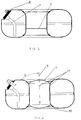
- the essence of the invention is that in a toroidal tank with two bottom plates connected to the central part in the form of a profiled tube of the base plates forms a part of the tank outer surface that is profiled in such a way that this Part of a flat plane at an acute angle to the horizontal plane of the tank forms.
- the flat level of the base plate has an instrument panel.
- the instrument panel contains something arranged inside the tank Sampling tube that it is close to that formed from the lower base plate Enough ground.
- the instrument panel also contains a safety valve.
- the middle part of the tank faces additional floor plates that close off the middle part of the tank.
- the middle one Tank part - the pipe part - preferably contains through openings.
- a toroidal tank, especially for liquefied gas according to the invention two interconnected base plates 1, 2, with a central part 3 in Form of a profiled tube, are connected.
- the bottom plates are as two den Tank-forming annular half-shells 1, 2 formed, the outside directly are connected to each other while inside on a short Pipe section 3 are connected.
- the upper base plate 1 has a part of the tank outer surface profiled in this way, that this one flat at an acute angle to the horizontal plane of the tank 5 Level 4 forms.
- the flat level 4 of the base plate 1 contains a fitting plate 6.
- Die Dashboard contains a removal pipe 7 directed into the interior of the tank and can contain a safety valve 8.
- the sampling tube 7 is bent so that it is up to close to the bottom of the tank.
- the tank bottom is through the second bottom plate 2 educated.
- the tank can additional, the tubular middle tank part 3 upwards and bottom bottom plates 9 and 10 included.
Landscapes
- Engineering & Computer Science (AREA)
- Mechanical Engineering (AREA)
- General Engineering & Computer Science (AREA)
- Life Sciences & Earth Sciences (AREA)
- Sustainable Development (AREA)
- Sustainable Energy (AREA)
- Chemical & Material Sciences (AREA)
- Combustion & Propulsion (AREA)
- Transportation (AREA)
- Filling Or Discharging Of Gas Storage Vessels (AREA)
Abstract
Description
- Fig. 1
- einen Tank mit einer Armaturenplatte und einem Entnahmerohr,
- Fig. 2
- einen Tank mit einer Armaturenplatte, einem Entnahmerohr und einer zusätzlichen Bodenplatte,
- Fig. 3
- einen Tank mit einer Armaturenplatte, einem Entnahmerohr und einem Ventil sowie einer zusätzlichen Bodenplatte, und
- Fig. 4
- einen Tank mit einer Armaturenplatte, einem Entnahmerohr, einem Ventil sowie zwei zusätzlichen Bodenplatten.
Claims (6)
- Toroidförmiger Tank, insbesondere für Flüssiggas, mit zwei mit einem mittleren Teil in Form eines profilierten Rohrs verbundenen ringförmigen Bodenplatten, die im wesentlichen halbschalenförmig die Oberseite und die Unterseite des Tanks bilden, dadurch gekennzeichnet, dass eine der Bodenplatten (1) einen so profilierten Teil der Tankaußenfläche aufweist, dass dieses eine in einem spitzen Winkel (d) zur Horizontalebene des Tanks (5) verlaufende flache Ebene (4) bildet.
- Toroidförmiger Tank nach Anspruch 1, dadurch gekennzeichnet, dass die flache Ebene (4) der Bodenplatte (1) eine Armaturenplatte (6) aufweist.
- Toroidförmiger Tank nach Anspruch 2, dadurch gekennzeichnet, dass die Armaturenplatte (6) ein in das Tankinnere gerichtetes Entnahmerohr (7) enthält, das bis nahe an den aus der unteren Bodenplatte (2) gebildeten Tankboden reicht.
- Toroidförmiger Tank nach Anspruch 2, dadurch gekennzeichnet, dass die Armaturenplatte (6) ein Sicherheitsventil (8) enthält.
- Toroidförmiger Tank nach Anspruch 1 oder 2, dadurch gekennzeichnet, dass er zusätzliche, den mittleren Tankteil (3) nach oben und unten abschließende Bodenplatten (9) und (10) aufweist.
- Toroidförmiger Tank nach Anspruch 1 oder 5, dadurch gekennzeichnet, dass er in dem mittleren Tankteil (3) seitliche Durchgangsöffnungen (11) zum Flüssigkeits- oder Gasdurchtritt in den umgebenden toroidförmigen Tankraum aufweist.
Applications Claiming Priority (2)
| Application Number | Priority Date | Filing Date | Title |
|---|---|---|---|
| PL02354298A PL354298A1 (en) | 2002-06-06 | 2002-06-06 | Toroidal tank, particularly liquid gas tank |
| PL35429802 | 2002-06-06 |
Publications (2)
| Publication Number | Publication Date |
|---|---|
| EP1376002A2 true EP1376002A2 (de) | 2004-01-02 |
| EP1376002A3 EP1376002A3 (de) | 2004-07-28 |
Family
ID=29717745
Family Applications (1)
| Application Number | Title | Priority Date | Filing Date |
|---|---|---|---|
| EP03012782A Withdrawn EP1376002A3 (de) | 2002-06-06 | 2003-06-05 | Toroidförmiger Tank, insbesondere für Flüssiggas |
Country Status (2)
| Country | Link |
|---|---|
| EP (1) | EP1376002A3 (de) |
| PL (1) | PL354298A1 (de) |
Family Cites Families (8)
| Publication number | Priority date | Publication date | Assignee | Title |
|---|---|---|---|---|
| IT1250793B (it) * | 1991-11-06 | 1995-04-21 | Icom Srl | Perfezionamenti ai serbatoi di g.p.l. con particolare riferimento al posizionamento dei gruppi valvolari. |
| IT235665Y1 (it) * | 1995-07-14 | 2000-07-12 | Icom Srl | Serbatoi per gpl per autotrazione predisposti per posizionamentoall'interno di una pompa o simile. |
| KR19990044504A (ko) * | 1995-09-05 | 1999-06-25 | 스캇 로빈슨 도널드 | 이중 챔버를 구비한 유체 저장 용기 |
| FR2756516A1 (fr) * | 1996-11-29 | 1998-06-05 | Barabino Alphonse | Bride multiple pour reservoirs gpl et reservoirs toriques securite bicarburation auto gpl |
| NL1004471C2 (nl) * | 1996-11-07 | 1998-05-14 | Vialle Beheer B V | Drukvatsamenstel. |
| PL187608B1 (pl) * | 1998-07-03 | 2004-08-31 | Staniuk Irena | Zbiornik toroidalny na gaz płynny |
| EP0969243A3 (de) * | 1998-07-03 | 2000-03-15 | Michael Staniuk | Toroidförmiger Tank für Flüssiggas |
| EP1291221A1 (de) * | 2001-09-07 | 2003-03-12 | Fratelli Ghezzi S.r.l. | Toroidförmiger Tank für Flüssiggas |
-
2002
- 2002-06-06 PL PL02354298A patent/PL354298A1/xx not_active IP Right Cessation
-
2003
- 2003-06-05 EP EP03012782A patent/EP1376002A3/de not_active Withdrawn
Also Published As
| Publication number | Publication date |
|---|---|
| PL354298A1 (en) | 2003-12-15 |
| EP1376002A3 (de) | 2004-07-28 |
Similar Documents
| Publication | Publication Date | Title |
|---|---|---|
| DE3242945C2 (de) | Ventilanordnung | |
| DE4018916A1 (de) | Tragbare saugpumpenvorrichtung fuer rueckstandsmotorenoel | |
| DE69629208T2 (de) | Treibstofffilter mit verbesserter verbindung zu einem behälter für verunreinigungen | |
| DE3009880A1 (de) | Druckbehaelter | |
| DE102017102721A1 (de) | Oberteil eines Straßenablaufs | |
| DE2454704C3 (de) | Katalytischer Umsetzer | |
| EP1237749B1 (de) | Flüssigkeitstank | |
| DE3142674A1 (de) | "tankcontainer" | |
| EP1369282A1 (de) | Gastank, insbesondere für Flüssiggas Propan-Butan | |
| DE29915384U1 (de) | Kombination aus einer Haupteinheit und wenigstens einer Anbau-Funktionseinheit | |
| DE69607150T2 (de) | Verbindungen von verteilerkanälen | |
| DE2708009A1 (de) | Fluessigkeitsdichtungsvorrichtung fuer ein gasstromsystem | |
| DE3543206A1 (de) | Trocknerbehaelter fuer klima- und/oder kuehlanlagen | |
| AT406833B (de) | Zusatzeinrichtung für eine vorrichtung zum reinigen metallischer fässer, insbesondere bierfässer | |
| EP0969243A2 (de) | Toroidförmiger Tank für Flüssiggas | |
| DE19850382A1 (de) | Vorrichtung zum Ablaß des in einem Bauteil eines Kraftfahrzeuges enthaltenen Öls | |
| DE3737162A1 (de) | Armatur mit schraubenlosem deckel | |
| DE10300119B4 (de) | Kondensatableiter | |
| EP1111350A1 (de) | Wasserzähler | |
| DE9414145U1 (de) | Domschacht für Behälter mit einem Doppelmantel, insbesondere für unterirdische Tanks für brennbare Flüssigkeiten | |
| EP1584858B1 (de) | Lagerungsvorrichtung für flüssiggas (varianten) | |
| DE9411024U1 (de) | Hydraulikaggregat | |
| DE102022122053A1 (de) | Druckflasche mit MTV-Ventil | |
| DE29610962U1 (de) | Abdeckelement, insbesondere für einen Kanalisationsschacht | |
| WO2020069966A1 (de) | Fluidventil, fahrzeug, verfahren zum abdichten |
Legal Events
| Date | Code | Title | Description |
|---|---|---|---|
| PUAI | Public reference made under article 153(3) epc to a published international application that has entered the european phase |
Free format text: ORIGINAL CODE: 0009012 |
|
| AK | Designated contracting states |
Kind code of ref document: A2 Designated state(s): AT BE BG CH CY CZ DE DK EE ES FI FR GB GR HU IE IT LI LU MC NL PT RO SE SI SK TR |
|
| AX | Request for extension of the european patent |
Extension state: AL LT LV MK |
|
| PUAL | Search report despatched |
Free format text: ORIGINAL CODE: 0009013 |
|
| AK | Designated contracting states |
Kind code of ref document: A3 Designated state(s): AT BE BG CH CY CZ DE DK EE ES FI FR GB GR HU IE IT LI LU MC NL PT RO SE SI SK TR |
|
| AX | Request for extension of the european patent |
Extension state: AL LT LV MK |
|
| RIC1 | Information provided on ipc code assigned before grant |
Ipc: 7B 60K 15/01 B Ipc: 7F 17C 1/00 A |
|
| 17P | Request for examination filed |
Effective date: 20050111 |
|
| AKX | Designation fees paid |
Designated state(s): AT BE BG CH CY CZ DE DK EE ES FI FR GB GR HU IE IT LI LU MC NL PT RO SE SI SK TR |
|
| 17Q | First examination report despatched |
Effective date: 20050323 |
|
| STAA | Information on the status of an ep patent application or granted ep patent |
Free format text: STATUS: THE APPLICATION IS DEEMED TO BE WITHDRAWN |
|
| 18D | Application deemed to be withdrawn |
Effective date: 20050803 |