EP1376101A1 - Vorrichtung zur Messung der photometrischen Eigenschaften eines Materials - Google Patents
Vorrichtung zur Messung der photometrischen Eigenschaften eines Materials Download PDFInfo
- Publication number
- EP1376101A1 EP1376101A1 EP03291458A EP03291458A EP1376101A1 EP 1376101 A1 EP1376101 A1 EP 1376101A1 EP 03291458 A EP03291458 A EP 03291458A EP 03291458 A EP03291458 A EP 03291458A EP 1376101 A1 EP1376101 A1 EP 1376101A1
- Authority
- EP
- European Patent Office
- Prior art keywords
- incidence
- angle
- optical processing
- main
- secondary optical
- Prior art date
- Legal status (The legal status is an assumption and is not a legal conclusion. Google has not performed a legal analysis and makes no representation as to the accuracy of the status listed.)
- Withdrawn
Links
Images


Classifications
-
- G—PHYSICS
- G01—MEASURING; TESTING
- G01N—INVESTIGATING OR ANALYSING MATERIALS BY DETERMINING THEIR CHEMICAL OR PHYSICAL PROPERTIES
- G01N21/00—Investigating or analysing materials by the use of optical means, i.e. using sub-millimetre waves, infrared, visible or ultraviolet light
- G01N21/17—Systems in which incident light is modified in accordance with the properties of the material investigated
- G01N21/47—Scattering, i.e. diffuse reflection
- G01N21/4738—Diffuse reflection, e.g. also for testing fluids, fibrous materials
- G01N21/474—Details of optical heads therefor, e.g. using optical fibres
-
- G—PHYSICS
- G01—MEASURING; TESTING
- G01N—INVESTIGATING OR ANALYSING MATERIALS BY DETERMINING THEIR CHEMICAL OR PHYSICAL PROPERTIES
- G01N2201/00—Features of devices classified in G01N21/00
- G01N2201/10—Scanning
- G01N2201/108—Miscellaneous
- G01N2201/1085—Using optical fibre array and scanner
Definitions
- the present invention relates to a device for measuring photometric characteristics of a material.
- the light arriving on these surfaces is reflected in transforming into light sources. This reflection is characterized by the luminance of the observed surface.
- This reflected luminance coefficient q ( ⁇ , ⁇ , ⁇ ) depends on the observation angle ⁇ of the luminance, the angles of incidence ⁇ and ⁇ of insolation.
- this known device called a gonio-photometer, is very bulky and does not allow measurement in situ. This known device requires the taking of a sample of the material to be exposed for analysis in the laboratory.
- the object of the present invention is to propose a device of small bulk which makes it possible to develop the photometric characteristics of a material in situ without sampling, directly on the surface to be analyzed.
- the angle of observation ⁇ is substantially equal to 1 ° by report to said plane of the surface to be exposed, to correspond to an angle according to which a driver would perceive the luminance reflected by one of the lighting devices for the lane on which it is traveling.
- CIE Committee International de l'Eclairage
- the luminance observed on said exposed material can be determined in situ in relation to the angles of incidence ⁇ and ⁇ , corresponding to different locations of the lighting devices.
- the surface analyzed is approximately 100 cm 2 in total to be representative of the material generally containing aggregates ranging in size from micron to centimeter; however, each of the secondary light beams does not allow the exposure of such a surface.
- each of said secondary light beams insulates only a part of said determined surface, each of said parts of said determined area preferably being 20 cm 2 .
- the device advantageously further comprises displacement means so that each of said light beams secondary successively insole each of said parts of said determined area and said means of acquiring and processing the signal transmitted by said sensor include means for developing overall photometric characteristics of said surface determined at from the signal transmitted by said luminance sensor for each of said parts of said surface determined in relation to said first and second angles of incidence ⁇ and ⁇ .
- the tangent of the first angle of incidence ⁇ is between 0 and 12 and the second angle incidence ⁇ is between 0 and 180 °.
- the means of development include advantageously a main light source emitting a beam main light and main optical processing means of the main light beam to generate a processed main beam and the processing means include N optical processing sets secondary and directive means for successively directing said main beam processed towards an entry of one of the N sets of secondary optical processing, each of said N processing sets secondary optics for processing said main light beam treated in a homogeneous and collimated secondary light beam.
- the main optical processing means are located between said main light source and said N sets of secondary optical processing.
- first and second angles of incidence being very important: twenty-nine for the first angles of incidence ⁇ and twenty for the second angles of incidence ⁇ , which, in combination, constitutes a palette of five hundred and eighty measures to carry out. It is therefore understood that for reasons of bulk of the device, it is best to minimize the number secondary optical processing sets and arranging them to allow the reconstruction of all five hundred and eighty luminances from a representative number of treatment sets secondary optics.
- This number of secondary optical processing units N is preferably equal to twenty-seven.
- the device for measuring photometric characteristics of a material illustrated in Figure 1A comprises a housing 10 in which is located a main source (not visible in Figure 1A) connected by through N optical fibers 12 to a movable head 14. Each of these N optical fibers is connected to an optical processing assembly secondary 16 detailed in FIG. 4.
- the assembly consisting of the housing 10, the N optical fibers and N secondary optical processing units 16, form of means 11 to develop N secondary light beams Homogeneous and collimated IV (see Figure 1B).
- Figure 1B shows that the housing 10 is connected to means signal acquisition and processing 18 to record the flow light emitted by one of the N secondary optical processing units 16 which is illuminated, as well as the luminance reflected by the material.
- the homogeneous and collimated secondary beam IV from of one of the N secondary optical processing units 16 insole a surface part 20 of a material 22 to be analyzed which in turn reflects the light received.
- the portion of light V reflected towards a luminance 24 makes it possible to determine using acquisition and signal processing 18, the luminance of the material 22 in relation to the secondary beam IV emitted.
- (O, X, Y, Z) be a reference defined with respect to the surface of the material 22 to be analyzed.
- Z axis coincides with normal not to said surface to be exposed;
- the plane (XOZ) corresponds to the plane along which the luminance measurement is carried out by the luminance sensor 24.
- the luminance sensor 24 is inclined by a viewing angle ⁇ substantially equal to 1 ° from the plane (XOY) and is arranged on the head mobile 14. This angle is preferably chosen in the plane (XOZ), this which corresponds to a distance from the X'X axis, in particular with respect to X.
- Each of the N secondary optical processing units 16 is disposed on the movable head 14 at a first angle of incidence ⁇ defined relative to the normal not and according to a second angle of incidence ⁇ defined in a plane P of said surface to be exposed.
- the first angle of incidence ⁇ is defined with respect to the axis Z, while the second angle of incidence ⁇ is defined with respect to the luminance sensor 24.
- the second angle of incidence ⁇ corresponds to the spacing between the secondary optical processing unit 16 considered and the luminance sensor 24, which returns, given the configuration of the latter, to consider the angle between the orthogonal projection of the secondary optical processing unit 16 considered 16 ′ (or treated secondary beam IV) on the surface to be analyzed 22, therefore the plane P or the plane (XOY) and the direction of the projection of the axis of the sensor luminance 24 in this same plane, that is to say with respect to the abscissa axis X'X, in particular with respect to X '.
- the movable head 14 comprising the N sets of secondary optical processing 16 and the luminance sensor 24, is disposed on a mobile support 26 having a mark (x, y, z) of so as to allow its displacement to expose all the part of the surface to be analyzed. Consequently, as soon as the mobile support 26 is placed substantially transversely on the material to be analyzed, its reference (x, y, z) is substantially coincident with the reference (X, Y, Z) of the material 22, so that all angles of sight and incidence can be defined in the reference (x, y, z) of the mobile support 26.
- the determined surface 28 of the material 22 to be analyzed is imposed by the International Lighting Committee (CIE) and is substantially equal to 100 cm 2 , so as to represent a correct sampling of the material 22 which generally has a structure having a particle size which can reach a few centimeters.
- CIE International Lighting Committee
- each of the N secondary light beams IV allows only a disk of diameter substantially equal to 5 cm to be exposed, which corresponds to a portion of surface 20 substantially equal to 20 cm 2 . Consequently, five measurements are made for each light beam IV, that is to say for each pair of angles of incidence ( ⁇ , ⁇ ), and are processed by processing and processing means 19 provided in the acquisition and processing means 18, preferably being averaged, in order to obtain an overall luminance of the determined surface 28.
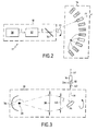
- the means 11 contain the main single source 30 emitting a main beam I and main optical processing means 32, as shown in Figure 2.
- the processing means 11 comprise directive means 34, in this case a rotating mirror 34, which are arranged between the main optical processing means 32 and the N sets of secondary optical processing 16. All other different directive means of a rotating mirror can be considered.
- the processing means main optic 32 include a spherical mirror 36 and at least one processing optics.
- the optical processing means main 32 have two processing optics, a first lens main converging lens 38 and a second converging main lens 40.
- the first converging main lens 38 has a diameter preferably equal to 100 mm with a focal length of preferably 150 mm and is arranged between 150 mm and 200 mm from the main light source 30, preferably 180 mm.
- the second converging main lens 40 has a diameter preferably equal to 80 mm with a focal length of preferably 100 mm and is placed between 200 mm and 250 mm from the light source main 30, preferably 214 mm.
- This arrangement of the main optical processing means 32 allows to recover a maximum of flux emitted by the light source main 30, in this case, for example a halogen lamp of a power preferably of the order of 100 W and send it to a N optical fibers 12 which each have a small diameter D12.
- this small diameter D12 preferably of the order of 3 mm, involves having a stable and precise direction of the light beam main treaty II to ensure good beam transmission secondary III returned by the rotating mirror 34 to one of the N sets of secondary optical processing 16.
- the housing 10 includes the main light source 30, but especially the directive means 34 for directing successively and precisely the main beam II treated towards the entrance 42 of one of the N optical fibers 12.
- the directive means 34 for directing successively and precisely the main beam II treated towards the entrance 42 of one of the N optical fibers 12.
- the means of main optical processing 32 make it possible to generate a beam main light treated II which is sufficiently convergent to reach the rotating mirror 34 precisely in order to be returned in one secondary beam III towards one of the inputs 42 of the N optical fibers 12.
- the housing 10 was mobile, it would be more difficult to ensure good transmission of the secondary beam III returned by the rotating mirror 34 towards the input 42 of an optical fiber 12, and therefore no certainty as to the measurement of the luminance carried out with respect to first and second angles of incidence ⁇ and ⁇ .
- each of the N sets secondary optical processing unit 16 includes a condenser 44 comprising at least one processing optic.
- the condenser 44 has a first converging secondary lens 46 and a second converging secondary lens 48. These two first and second converging secondary lenses 46 and 48 are preferably similar and each have a diameter preferably of the order of 25 mm with a focal length of the order of 15 mm.
- each of the N secondary optical processing units 16 comprises a preferably elliptical diaphragm 50 which is arranged before the inlet 52 of the condenser 44.
- Figure 5 shows a sectional view of the elliptical diaphragm 50 which has a large axis A1 of length L and a small axis A2 of length l.
- each of the N sets of secondary optical processing 16 further comprises an optical collimator, in this case a third converging secondary lens 54 preferably having a diameter of the order of 70 mm with a focal length of the order of 100 mm.
- This third converging secondary lens 54 has a FO54 object focus and an image focus (not shown), said object focus FO54 being confused with the image focal point of a processing optic condenser 44, in this case with the focus image FI48 of the second secondary converging lens 48.
- all the beams secondary III 'from this second converging secondary lens 48 converge at the object focus FO54 of the third secondary lens convergent 54, so that all the secondary IV beams coming from this third lens 54 are mutually parallel.
- the secondary beams IV coming from one of the N sets of secondary optical processing 16 are homogeneous and collimated.
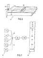
- the luminance sensor 24 comprises a converging lens 58, a diaphragm 60 of small aperture and a detector 66, as illustrated in figure 6.
- the converging lens 58 is preferably of diameter of around 70 mm with a focal length around 150 mm and the diaphragm 60 has an opening which is preferably of the order of 1 mm of diameter. Consequently, the parallel beams V reflected by the surface under observation angle ⁇ of 1 ° (see also Figure 1A) converge on the input 62 of a multifibre optic 64 of diameter preferably of the order of 3 mm to conduct the light towards the detector 66.
- the detector 66 of the luminance 24 is preferably a photomultiplier which allows to amplify the light flux transmitted in the optical multifiber 64.
- the device for measure further comprises means 68 for reconstructing the luminance of said exposed surface as a function of at least a first and a second angle of incidence ⁇ and ⁇ chosen, from a plurality of photometric characteristics determined for a plurality of prime and second angles of incidence ⁇ and ⁇ fixed.
- the number of different first and second angles of incidence imposed by the CIE being five hundred and eighty luminances (matrix corresponding to the first twenty-nine angles of incidence ⁇ , including the tangent of each is between 0 and 12, and twenty second angles of incidence ⁇ , each being between 0 and 180 °), it is not possible to have as many secondary light beams IV.
- the calculation of the coefficients of specularities S 1 and S 2 (representing the specular reflection in a favored direction) and of the clarity Q 0 is preferable to allow a good filling of the aforementioned matrix 70 from the measurement of at least one pair of luminances.
- the first angle of incidence ⁇ could for example be chosen to obtain a tangent between 0 and 5, preferably among the values of the order of 0.5, 1, 2 and 4, while the second angle of incidence ⁇ may for example be chosen between 0 ° and 200 °, preferably among the values of the order of 0 °, 15 °, 30 °, 60 °, 90 °, 135 ° and 180 °.
Landscapes
- Physics & Mathematics (AREA)
- Health & Medical Sciences (AREA)
- Life Sciences & Earth Sciences (AREA)
- Chemical & Material Sciences (AREA)
- Analytical Chemistry (AREA)
- Biochemistry (AREA)
- General Health & Medical Sciences (AREA)
- General Physics & Mathematics (AREA)
- Immunology (AREA)
- Pathology (AREA)
- Investigating Or Analysing Materials By Optical Means (AREA)
Applications Claiming Priority (2)
| Application Number | Priority Date | Filing Date | Title |
|---|---|---|---|
| FR0207467A FR2840990B1 (fr) | 2002-06-18 | 2002-06-18 | Dispositif de mesure de caracteristiques photometriques d'un materiau |
| FR0207467 | 2002-06-18 |
Publications (1)
| Publication Number | Publication Date |
|---|---|
| EP1376101A1 true EP1376101A1 (de) | 2004-01-02 |
Family
ID=29595329
Family Applications (1)
| Application Number | Title | Priority Date | Filing Date |
|---|---|---|---|
| EP03291458A Withdrawn EP1376101A1 (de) | 2002-06-18 | 2003-06-17 | Vorrichtung zur Messung der photometrischen Eigenschaften eines Materials |
Country Status (2)
| Country | Link |
|---|---|
| EP (1) | EP1376101A1 (de) |
| FR (1) | FR2840990B1 (de) |
Cited By (1)
| Publication number | Priority date | Publication date | Assignee | Title |
|---|---|---|---|---|
| US5918697A (en) * | 1996-01-04 | 1999-07-06 | Daimler-Benz Ag | Operating-element control arrangement for motor vehicle longitudinal movement |
Families Citing this family (2)
| Publication number | Priority date | Publication date | Assignee | Title |
|---|---|---|---|---|
| FR2944872B1 (fr) | 2009-04-23 | 2013-05-17 | Roch Service | Mesure de la luminance d'une surface de voirie |
| DE102010038280B4 (de) * | 2010-07-22 | 2014-10-02 | Gesellschaft zur Förderung von Medizin-, Bio- und Umwelttechnologien e.V. | Verfahren und Anordnung zur Messung des mittleren Leuchtdichtekoeffizienten von Straßenoberflächen |
Citations (6)
| Publication number | Priority date | Publication date | Assignee | Title |
|---|---|---|---|---|
| US4572672A (en) * | 1982-02-19 | 1986-02-25 | Imperial Chemical Industries Plc | Surface coating characterization method and apparatus |
| US4583858A (en) * | 1981-11-17 | 1986-04-22 | Deutsche Akzo Coatings & Byk-Mellinckrodt Chemische Products, GmbH | Device for use in chromatometry of samples |
| WO1987007381A1 (en) * | 1986-05-27 | 1987-12-03 | Roibox Oy | Method for measuring of gloss and equipment for application of method |
| EP0286165A1 (de) * | 1987-03-26 | 1988-10-12 | Advanced Production Automation B.V. | Gerät zum Führen von Laserenergie in Fasern |
| EP0335192A2 (de) * | 1988-03-28 | 1989-10-04 | Pacific Scientific Company | Instrument zur kombinierten Messung von Glanz und Farbe |
| EP0375317A2 (de) * | 1988-12-20 | 1990-06-27 | E.I. Du Pont De Nemours And Company | Tragbares Kolorimeter und Verfahren zur Kennzeichnung einer farbigen Oberfläche |
-
2002
- 2002-06-18 FR FR0207467A patent/FR2840990B1/fr not_active Expired - Lifetime
-
2003
- 2003-06-17 EP EP03291458A patent/EP1376101A1/de not_active Withdrawn
Patent Citations (6)
| Publication number | Priority date | Publication date | Assignee | Title |
|---|---|---|---|---|
| US4583858A (en) * | 1981-11-17 | 1986-04-22 | Deutsche Akzo Coatings & Byk-Mellinckrodt Chemische Products, GmbH | Device for use in chromatometry of samples |
| US4572672A (en) * | 1982-02-19 | 1986-02-25 | Imperial Chemical Industries Plc | Surface coating characterization method and apparatus |
| WO1987007381A1 (en) * | 1986-05-27 | 1987-12-03 | Roibox Oy | Method for measuring of gloss and equipment for application of method |
| EP0286165A1 (de) * | 1987-03-26 | 1988-10-12 | Advanced Production Automation B.V. | Gerät zum Führen von Laserenergie in Fasern |
| EP0335192A2 (de) * | 1988-03-28 | 1989-10-04 | Pacific Scientific Company | Instrument zur kombinierten Messung von Glanz und Farbe |
| EP0375317A2 (de) * | 1988-12-20 | 1990-06-27 | E.I. Du Pont De Nemours And Company | Tragbares Kolorimeter und Verfahren zur Kennzeichnung einer farbigen Oberfläche |
Non-Patent Citations (1)
| Title |
|---|
| BOMMEL, BURGHOUT, COBB, FISHER, GORKUM, HEYSTRAETEN ET AL.: "Road Surfaces and lighting", INTERNATIONAL COMMISSION ON ILLUMINATION. JOINT TECHNICAL REPORT CIE/PIARC, vol. 66, 1984, Paris (France), XP002258261 * |
Cited By (1)
| Publication number | Priority date | Publication date | Assignee | Title |
|---|---|---|---|---|
| US5918697A (en) * | 1996-01-04 | 1999-07-06 | Daimler-Benz Ag | Operating-element control arrangement for motor vehicle longitudinal movement |
Also Published As
| Publication number | Publication date |
|---|---|
| FR2840990B1 (fr) | 2005-07-29 |
| FR2840990A1 (fr) | 2003-12-19 |
Similar Documents
| Publication | Publication Date | Title |
|---|---|---|
| US8437002B2 (en) | Imaging optical inspection device with a pinhole camera | |
| EP3069185B1 (de) | Dreidimensionale fokussierungsvorrichtung und verfahren für ein mikroskop | |
| EP0712009A1 (de) | Integriertes Winkelabweichungs-Messsystem | |
| EP2810049B1 (de) | Optisches system zur messung von brdf, bsdf und bdtf | |
| EP1084379B1 (de) | Optoelektronische Formerfassung durch chromatische Kodierung mit Beleuchtungsebenen | |
| FR2749388A1 (fr) | Appareil de mesure des caracteristiques photometriques et colorimetriques d'un objet | |
| EP1224444B1 (de) | Vorrichtung zur bestimmung der räumlichen verteilung der spektralen emission eines objekts | |
| CA2166662C (fr) | Dispositif de mesure colorimetrique d'un ecran d'affichage | |
| FR2458822A1 (fr) | Dispositif optoelectrique de detection, notamment de rayonnement laser, et systeme comportant un tel dispositif | |
| EP0970391B1 (de) | Optisches gerät zur kontaktlosen messung des abstandes zu einer lichtquelle | |
| FR2597618A1 (fr) | Telescope spatial relie a un localisateur d'etoiles | |
| EP1376101A1 (de) | Vorrichtung zur Messung der photometrischen Eigenschaften eines Materials | |
| EP0429332A1 (de) | Verfahren und Anordnung zur Bestimmung der Charakteristiken einer Linse, insbesondere ihrer Stärke | |
| WO2008003852A1 (fr) | Dispositif d'evaluation de l'etat de mouillage d'une surface, procede d'evaluation et dispositif d'indication associe | |
| WO2005036141A1 (fr) | Dispositif portable de mesure de l'intensité lumineuse d'un objet et utilisation d'un tel dispositif | |
| FR2661518A1 (fr) | Procede d'harmonisation entre l'axe d'une lunette de visee et celui d'une camera thermique. | |
| FR2710146A1 (fr) | Dispositif optique de mesure d'écart transversal. | |
| FR2845487A1 (fr) | Systeme de collecte de lumiere, amplificateur, achromatique et d'absorption reduite, particulierement adapte a l'analyse spectrometrique optique | |
| FR3059156B1 (fr) | Module de detection optique | |
| FR2730823A1 (fr) | Procede et dispositif de reglage d'un montage de collimation par miroir parabolique hors d'axe | |
| FR2715470A1 (fr) | Dispositif d'étude des propriétés d'émission lumineuse d'une surface émettrice de lumière. | |
| FR2753277A1 (fr) | Procede de calibration d'un banc de mesure de surfaces equivalentes laser | |
| FR2632723A1 (fr) | Systeme de detection pour photometre | |
| FR2776067A1 (fr) | Systeme de determination et de quantification de l'alignement d'un objet avec une optique de couplage et un dispositif de prise de vues | |
| FR2815424A1 (fr) | Dispositif a surface equivalente laser parfaitement connue et procede associe |
Legal Events
| Date | Code | Title | Description |
|---|---|---|---|
| PUAI | Public reference made under article 153(3) epc to a published international application that has entered the european phase |
Free format text: ORIGINAL CODE: 0009012 |
|
| AK | Designated contracting states |
Kind code of ref document: A1 Designated state(s): AT BE BG CH CY CZ DE DK EE ES FI FR GB GR HU IE IT LI LU MC NL PT RO SE SI SK TR |
|
| AX | Request for extension of the european patent |
Extension state: AL LT LV MK |
|
| 17P | Request for examination filed |
Effective date: 20040624 |
|
| AKX | Designation fees paid |
Designated state(s): AT BE BG CH CY CZ DE DK EE ES FI FR GB GR HU IE IT LI LU MC NL PT RO SE SI SK TR |
|
| 17Q | First examination report despatched |
Effective date: 20061220 |
|
| STAA | Information on the status of an ep patent application or granted ep patent |
Free format text: STATUS: THE APPLICATION IS DEEMED TO BE WITHDRAWN |
|
| 18D | Application deemed to be withdrawn |
Effective date: 20070503 |