EP1376152A2 - Verfahren und Vorrichtung zum Kalibrieren einer HF-Einrichtung - Google Patents
Verfahren und Vorrichtung zum Kalibrieren einer HF-Einrichtung Download PDFInfo
- Publication number
- EP1376152A2 EP1376152A2 EP03007608A EP03007608A EP1376152A2 EP 1376152 A2 EP1376152 A2 EP 1376152A2 EP 03007608 A EP03007608 A EP 03007608A EP 03007608 A EP03007608 A EP 03007608A EP 1376152 A2 EP1376152 A2 EP 1376152A2
- Authority
- EP
- European Patent Office
- Prior art keywords
- signal
- delay
- calibration
- pulse
- raw
- Prior art date
- Legal status (The legal status is an assumption and is not a legal conclusion. Google has not performed a legal analysis and makes no representation as to the accuracy of the status listed.)
- Withdrawn
Links
Images

Classifications
-
- G—PHYSICS
- G01—MEASURING; TESTING
- G01S—RADIO DIRECTION-FINDING; RADIO NAVIGATION; DETERMINING DISTANCE OR VELOCITY BY USE OF RADIO WAVES; LOCATING OR PRESENCE-DETECTING BY USE OF THE REFLECTION OR RERADIATION OF RADIO WAVES; ANALOGOUS ARRANGEMENTS USING OTHER WAVES
- G01S7/00—Details of systems according to groups G01S13/00, G01S15/00, G01S17/00
- G01S7/02—Details of systems according to groups G01S13/00, G01S15/00, G01S17/00 of systems according to group G01S13/00
- G01S7/40—Means for monitoring or calibrating
- G01S7/4004—Means for monitoring or calibrating of parts of a radar system
- G01S7/4017—Means for monitoring or calibrating of parts of a radar system of HF systems
-
- G—PHYSICS
- G01—MEASURING; TESTING
- G01S—RADIO DIRECTION-FINDING; RADIO NAVIGATION; DETERMINING DISTANCE OR VELOCITY BY USE OF RADIO WAVES; LOCATING OR PRESENCE-DETECTING BY USE OF THE REFLECTION OR RERADIATION OF RADIO WAVES; ANALOGOUS ARRANGEMENTS USING OTHER WAVES
- G01S13/00—Systems using the reflection or reradiation of radio waves, e.g. radar systems; Analogous systems using reflection or reradiation of waves whose nature or wavelength is irrelevant or unspecified
- G01S13/02—Systems using reflection of radio waves, e.g. primary radar systems; Analogous systems
- G01S13/0209—Systems with very large relative bandwidth, i.e. larger than 10 %, e.g. baseband, pulse, carrier-free, ultrawideband
-
- G—PHYSICS
- G01—MEASURING; TESTING
- G01S—RADIO DIRECTION-FINDING; RADIO NAVIGATION; DETERMINING DISTANCE OR VELOCITY BY USE OF RADIO WAVES; LOCATING OR PRESENCE-DETECTING BY USE OF THE REFLECTION OR RERADIATION OF RADIO WAVES; ANALOGOUS ARRANGEMENTS USING OTHER WAVES
- G01S13/00—Systems using the reflection or reradiation of radio waves, e.g. radar systems; Analogous systems using reflection or reradiation of waves whose nature or wavelength is irrelevant or unspecified
- G01S13/02—Systems using reflection of radio waves, e.g. primary radar systems; Analogous systems
- G01S13/06—Systems determining position data of a target
- G01S13/08—Systems for measuring distance only
- G01S13/10—Systems for measuring distance only using transmission of interrupted, pulse modulated waves
- G01S13/18—Systems for measuring distance only using transmission of interrupted, pulse modulated waves wherein range gates are used
-
- G—PHYSICS
- G01—MEASURING; TESTING
- G01S—RADIO DIRECTION-FINDING; RADIO NAVIGATION; DETERMINING DISTANCE OR VELOCITY BY USE OF RADIO WAVES; LOCATING OR PRESENCE-DETECTING BY USE OF THE REFLECTION OR RERADIATION OF RADIO WAVES; ANALOGOUS ARRANGEMENTS USING OTHER WAVES
- G01S7/00—Details of systems according to groups G01S13/00, G01S15/00, G01S17/00
- G01S7/02—Details of systems according to groups G01S13/00, G01S15/00, G01S17/00 of systems according to group G01S13/00
- G01S7/28—Details of pulse systems
- G01S7/282—Transmitters
Definitions
- the present invention relates to a method and a Device for calibrating an HF device.
- RF systems are widely used today for measurement processes, in particular Distance and speed measurements of objects, used. This is of particular importance high-frequency measurement (radar) around vehicles.
- radar high-frequency measurement
- Distance measuring devices the to detect distances and relative speeds are particularly suitable intended as short-range radar systems for automobiles.
- a number of individual sensors are used Arranged around an automobile.
- SRR Short Range Radar
- RF pulses which, for. B. a typical 400 ps wide.
- a common SRR system uses a delay circuit one that targets the receive pulse versus the transmit pulse delayed.
- the delay that the to be detected Distance cell corresponds is created by creating a predetermined voltage level set. For measurement of the entire distance range becomes the delay circuit from the smallest to the greatest value or vice versa adjusted.
- the accuracy with which the delay circuit is set distance measurement accuracy For determining the angle at which detected an object, particularly in the vicinity of a vehicle is the measurement of the object with at least two individual sensors required.
- the angle value can by Evaluation of the measured individual distances using the Triangulation can be obtained.
- Crucial for the angular measurement accuracy is therefore also the one in the individual sensors achievable measurement accuracy for distance measurement.
- the method according to the invention or the one according to the invention Device for calibrating an HF device with the Features of claim 1 points over the known approach the advantage that in operation z. B. the SRR if necessary, a zero adjustment can be carried out during the measuring cycle is. This can result in recalibration of the system and the measuring accuracy can be increased.
- the idea on which the present invention is based exists essentially using a radar signal which arises when a send and a receive switch are switched to continuity at the same time. Then the radar sees itself, e.g. B. internal couplings and antenna overcoupling, which occurs during the removal of 0 m or at the defined distance between transmit and Reception device occur.
- This reproducible Distance information of the SRR includes the running times of the complete chain of delays covering the terms of the Includes baseband pulse generators, RF switches and antennas, with which all influences of these components are calibrated out can be.
- this is used to calibrate an HF device an input signal in a transmission control signal and a receive drive signal is split, the transmit drive signal in a delay device for triggering of a transmit pulse is delayed, the receive drive signal in Dependence of a delay formation signal and / or a calibration signal in a controllable delay device for selective triggering of a receive pulse selectively delayed, and an RF raw signal, in particular a received radar signal into the delay information signal and / or the calibration signal in a signal processing device for calibrating the HF device scanned and processed.
- the signal processing device dependent on the raw RF signal the present delay of the transmission control signal an absolute zero point and thus an offset of the HF device determined in which both the transmission pulse as the reception pulse can also be activated at the same time.
- determination is carried out differentiates the raw RF signal from the absolute zero point, a threshold for determining the slope of a Edge of the RF raw signal is determined and if the threshold is exceeded, the absolute becomes at this point Zero point or the offset is determined from the raw RF signal.
- the selective Delay of the receive control signal in the controllable Delay device for calibration or Adjusted zero adjustment of the HF device makes possible the actual calibration out of the undesirable ones Effects such as B. the temperature dependence.
- the Calibration via the calibration signal, in particular a Voltage signal, which an offset control input of controllable delay device is supplied.
- the detected offset will not be possible via the delay information signal to control and thus the scan area not to restrict, but the offset adjustment or zero point calibration using the calibration signal to be carried out separately.
- this is the controllable delay device supplied delay information signal a digital word, which in particular has a length of 8 bits. This has the advantage that that generated in the signal processing device Delay information signal using a microprocessor can be edited.
- the self-calibrating HF device for Distance and / or speed determination of objects, in particular with short-range pulse radar. This has the advantage that due to the possibility of calibration of the HF device precise, reproducible measurement results in the measuring insert be achieved.
- the Self-calibration of the HF device at and / or in front of everyone Distance measurement of the HF device carried out. Thereby becomes a permanent recalibration of the arrangement allows.
- the Delay device a static delay before which in particular a filter device z. B. from one Resistor and a capacitor and / or one Has pulse shaper. Due to the static provided Delay, the transmission control signal is advantageous delayed by a certain known time period and transmit pulses of a predetermined length are provided.
- the Signal processing device a processor on which an algorithm for determining a zero point or offset can be processed from the raw RF signal. This has the advantage of digital data processing and thus a possible one Miniaturization of the signal processing device.
- controllable delay device a digital / analog Converting means for converting the digital delay information signal into an analog signal, in particular into an analog voltage signal. This will make one analogue processing of the delay information signal in the controllable delay device.
- controllable delay device a function generator for generating a ramp-shaped signal from the reception drive signal depending on the calibration signal on. This enables the advantageous offset calibration separate from the actual controllable delay to Capture the scan area.
- controllable delay device a comparator, in particular a TTL comparator to compare the ramp-shaped Signal with the analog signal and to output a Comparison signal. This makes it controllable Delay of the receive control signal ensured.
- controllable delay device a linear delay curve proportional with constant and known increase to the delay information signal. This has the advantage that directly through signal size changes proportional, linear delays of the receive control signal be achieved.
- these are Transmit control signal and the receive control signal with a Pulse repetition rate (PRF) applied square wave signals with TTL levels, e.g. B. in a repetition rate frequency range from 1 MHz to 10 MHz.
- PRF Pulse repetition rate
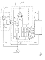
- Figure 1 shows a schematic block diagram for explanation an embodiment of the present invention.
- an input signal 10 in particular a Rectangular signal, which with TTL levels and a pulse repetition frequency (PRF) for example between 1 MHz and 10 MHz is provided in a transmission control signal 11 and reception control signal 12 split.
- the transmission control signal 11 is fed to a delay device 13, which in particular a static delay z. B. means a filter device 14, 15 from a resistor 14 and a capacitor grounded with an electrode 15 provides.
- the delay device has pulse processing 13 a pulse shaper 16, which pulses z. B. generated a length of 400 ps.
- the delay device 13 gives a constantly delayed transmission control signal 17 to trigger a transmission pulse.
- An RF raw signal 18, in particular a received radar raw signal, is fed to a signal processing device 19, in which the radar raw signal 18 is detected and in particular using an algorithm on a digital processor is processed.
- the raw RF signal 18 becomes a delay information signal 20 generated, which is a controllable delay device 21 is supplied.
- One in the signal processing device 19 optionally generated calibration signal 22 is also the controllable delay device 21 fed.
- the controllable delay device 21 delays this Receive drive signal 12 in response to the delay information signal 20, which in particular is a digital word z. B. provides with a word length of 8 bits, and / or depending on the calibration signal 22.
- the controllable delay device 21 shows a linear deceleration curve with a known, i.e. H. adjustable and constant incline, whereby that the actual delay that the controllable Delay device 21 generated, proportional to one set delay runs, with the proportionality factor due to external influences such as B. the temperature or component fluctuations essentially does not change.
- the receive drive signal 12 through the delay means 21 and the externally applied manipulated variables 20, 22 Delayed in a targeted manner.
- the delay information signal 20 is e.g. B. as 8 bit Data word on the inputs 23 to 30 of the controllable delay device 21 fed.
- the controllable delay device 21 becomes the delay information signal 20 preferably stored using TTL latches 31 before the digital data word of the delay information signal 20 in a D / A converter 32 into an analog signal 33, preferably a voltage signal is converted.
- the receive control signal 12 is fed to the controllable delay device 21 via a trigger input 34 and forwarded to a trigger circuit 35, which is also connected on the input side to a reset input 36, via which the trigger circuit 35 can be reset.
- the trigger circuit 35 is followed by a function generator 37, which preferably generates a ramp-shaped signal 39 as a function of the reception control signals 12 supplied via the trigger input 34 and the calibration signal 22 which is input to the controllable delay device 21 via a calibration or offset adaptation input 38 ,
- the function generator 37 or the generated function can preferably be influenced via two further inputs R SET 40 and C EXT 41.
- a comparison device in particular a TTL comparator, compares the ramp-shaped signal 39 with the analog signal 33 and generates a selectively delayed receive drive signal 43, whose delay is proportional to the applied Delay information signal 20.
- the reception drive signal 12 becomes variable with the help of the controllable delay device 21 preferably digitally delayed while the transmit control signal 11 firmly delayed in the delay device 13 becomes.
- the raw radar signal 18 provides the information as to when to the relative delay of the transmit trigger 17 Zero occurs, d. H. what time period passes until the transmission signal of a transmission device as a reception signal / which is received via a receiving device is, directly, d. H. without an object to it To reflect distance determination, is detected. This time can either z. B. by an 8 bit Represent input word 20 and can for the further absolute Distance calculation can be used or directly over the calibration signal 22 of the controllable delay device 21 are supplied, so that for example digital data word 00000000 as delay information signal 20 set to the absolute distance zero becomes.
- FIG. 2 shows a signal diagram to explain the operation an embodiment of the present invention.
- the received radar raw signal 18 is above the Time axis t 44 shown.
- Time 45 describes this simultaneous opening or activation of transmit and receive pulse. Because the shape of the raw signal from sensor to sensor can be different, it is necessary to use an algorithm to provide a reliable of these variations Assigns zero point information.
- the following algorithm is to be calibrated in the signal processing device 19 according to FIG. 1 processed, provided: differentiation of the raw signal 18; Setting a threshold for determining the slope the edge 46 of the raw signal 18, setting the zero point indicator when the threshold is exceeded.
- An offset of this Indicator of the actual zero point at the send and Reception switches are open at the same time, is measured once determined and is essentially from sensor to sensor constant and is included in the calibration.
- each amplitude value of the radar raw signal 18 according to FIG 2 can be assigned a point in time on the time axis 44 can also result in a distance assignment the raw radar signal 18. Scanning for calibration takes place starting from negative distances, the in of the data processing device 19 according to FIG Algorithm the first peak in the output signal as a zero signal recognizes and calculates the exact position of the zero point. Early peaks are physical not possible and consequently the assignment of the zero signal clearly. The measured offset or the measured time delay is saved and all, actually Objects that are detected by the measurement scan are thus corrected.
- the calibration scan makes sense after the detection a temperature change of e.g. B. 5 ° C and / or after performed at a certain time interval.
- a temperature change e.g. B. 5 ° C and / or after performed at a certain time interval.
- the calibration and distance measurement always be carried out together and thus always scanned from negative distances is, the distances of the detected objects in Measurement scan with a zero signal corresponding to the offset, which is recalculated for each scan are corrected.
- the zero point which is opened when the transmit and Receive switch occurs, is not necessarily at the first, second peak or zero crossing.
- controllable delay device which is a component of the company Analog Devices (AD 9501) corresponds, but also with other components e.g. ASICs similar properties can be realized.
Landscapes
- Engineering & Computer Science (AREA)
- Radar, Positioning & Navigation (AREA)
- Remote Sensing (AREA)
- Computer Networks & Wireless Communication (AREA)
- Physics & Mathematics (AREA)
- General Physics & Mathematics (AREA)
- Radar Systems Or Details Thereof (AREA)
Abstract
Description
- Fig. 1
- ein schematisches Blockdiagramm zur Erläuterung einer Ausführungsform der vorliegenden Erfindung; und
- Fig. 2
- ein Signalschaubild zur Erläuterung einer Funktionsweise einer Ausführungsform der vorliegenden Erfindung.
Claims (19)
- Verfahren zum Kalibrieren einer HF-Einrichtung mit den Schritten:Aufspalten eines Eingangssignals (10) in ein Sendeansteuersignal (11) und ein Empfangsansteuersignal (12);Verzögern des Sendeansteuersignals (11) in einer Verzögerungseinrichtung (13) zum Triggern eine Sendepulses (17);selektives Verzögern des Empfangsansteuersignals (12) in Abhängigkeit eines Verzögerungsinformationssignals (20) und/ oder eines Kalibrierungssignals (22) in einer steuerbaren Verzögerungseinrichtung (21) zum selektiven Triggern eines Empfangspulses (43); undAbtasten und Verarbeiten eines HF-Rohsignals (18) in das Verzögerungsinformationssignal (20) und/oder das Kalibrierungssignal (22) in einer Signalverarbeitungseinrichtung (19) zum Kalibrieren der HF-Einrichtung.
- Verfahren nach Anspruch 1,
dadurch gekennzeichnet, dass in der Signalverarbeitungseinrichtung (19) aus dem HF- Rohsignal (18) in Abhängigkeit der vorliegenden Verzögerung des Sendeansteuersignals (17) ein absoluter Nullpunkt und somit ein Offset der HF-Einrichtung ermittelt wird, bei welchem sowohl der Sendepuls (17) als auch der Empfangspuls (43) gleichzeitig aktiviert werden. - Verfahren nach Anspruch 2,
dadurch gekennzeichnet, dass zum Ermitteln des absoluten Nullpunkts das HF-Rohsignal (18) differenziert wird, ein Schwellwert zur Bestimmung der Steigung einer Flanke (46) des HF- Rohsignals (18) bestimmt wird, und wenn dieser Schwellwert überschritten wird an dieser Stelle der absolute Nullpunkt bzw. der Offset aus dem HF- Rohsignal (18) bestimmt wird. - Verfahren nach einem der vorangehenden Ansprüche 2 oder 3,
dadurch gekennzeichnet, dass auf Basis des ermittelten Nullpunktes bzw. des Offsets die selektive Verzögerung des Empfangsansteuersignals (12) in der steuerbaren Verzögerungseinrichtung (21) zur Kalibrierung bzw. zum Nullabgleich der HF-Einrichtung angepasst wird. - Verfahren nach Anspruch 4,
dadurch gekennzeichnet, dass die Kalibrierung über das Kalibrierungssignal (22), insbesondere ein Spannungssignal, erfolgt, welches einem Offsetsteuereingang (38) der steuerbaren Verzögerungseinrichtung (21) zugeführt wird. - Verfahren nach einem der vorangehenden Ansprüche,
dadurch gekennzeichnet, dass das der steuerbaren Verzögerungseinrichtung (21) zugeführte Verzögerungsinformationssignal (20) ein Digitalwort ist, welches insbesondere eine Länge von 8-bit aufweist. - Verfahren nach einem der vorangehenden Ansprüche,
dadurch gekennzeichnet, dass die Kalibrierung der HF-Einrichtung nach einer von außen detektierten vorbestimmten Temperaturänderung und/oder nach einem vorbestimmten Zeitintervall durchgeführt wird. - Verfahren nach einem der vorangehenden Ansprüche,
dadurch gekennzeichnet, dass die selbstkalibrierende HF-Einrichtung zur Entfernungs- und/oder Geschwindigkeitsbestimmung von Objekten, insbesondere mit einem Nahbereichs Pulsradar, eingesetzt wird. - Verfahren nach Anspruch 8,
dadurch gekennzeichnet, dass die Selbstkalibrierung der HF-Einrichtung bei und/oder vor jeder Entfernungsmessung der HF-Einrichtung durchgeführt wird. - Vorrichtung zur Kalibrierung einer HF-Einrichtung mit:einer Verzögerungseinrichtung (13) zum Verzögern eines Sendeansteuersignals (11) zum Triggern eine Sendepulses (17);einer steuerbaren Verzögerungseinrichtung (21) zum selektiven Verzögern eines Empfangsansteuersignals (12) in Abhängigkeit eines Verzögerungsinformationssignals (20) und/ oder eines Kalibrierungssignals (22) zum selektiven Triggern eines Empfangspulses (12); undeiner Signalverarbeitungseinrichtung (19) zum Abtasten und zum Verarbeiten eines HF-Rohsignals (18) in das Verzögerungsinformationssignal (20) und/oder das Kalibrierungssignal (22) zum Kalibrieren der HF-Einrichtung.
- Vorrichtung nach Anspruch 10,
dadurch gekennzeichnet, dass die Verzögerungseinrichtung (13) eine statische Verzögerung vorsieht, welche insbesondere eine Filtereinrichtung (14, 15) z. B. aus einem Widerstand (14) und einem Kondensator (15) und/oder einen Pulsformer (16) aufweist. - Vorrichtung nach einem der vorangehenden Ansprüche 10, 11,
dadurch gekennzeichnet, dass die Signalverarbeitungseinrichtung (19) einen Prozessor aufweist, auf welchem ein Algorithmus zum Bestimmen eines Nullpunkts bzw. Offsets aus dem HF-Rohsignal abarbeitbar ist. - Vorrichtung nach einem der vorangehenden Ansprüche 10 bis 12,
dadurch gekennzeichnet, dass die steuerbare Verzögerungseinrichtung (21) mindestens einen Eingang (23 bis 30) zum Zuführen des Verzögerungsinformationssignals (20) aufweist, welches insbesondere digital in einer TTL- Latch- Speichereinrichtung (31) speicherbar ist. - Vorrichtung nach einem der vorangehenden Ansprüche 10 bis 13,
dadurch gekennzeichnet, dass die steuerbare Verzögerungseinrichtung (21) eine digital/analog Umwandlungseinrichtung (32) zum Umwandeln des digitalen Verzögerungsinformationssignals (20) in ein Analogsignal (33), insbesondere ein analoges Spannungssignal, aufweist. - Vorrichtung nach einem der vorangehenden Ansprüche 10 bis 14,
dadurch gekennzeichnet, dass die steuerbare Verzögerungseinrichtung (21) einen Funktionsgenerator (37) zum Erzeugen eines rampenförmigen Signals (39) aus dem Empfangsansteuersignal (12) in Abhängigkeit von dem Kalibrierungssignal (22) aufweist. - Vorrichtung nach Anspruch 15,
dadurch gekennzeichnet, dass die steuerbare Verzögerungseinrichtung (21) eine Vergleichseinrichtung (42), insbesondere einen TTL-Komparator, zum Vergleichen des rampenförmigen Signals (39) mit dem Analogsignal (33) und zum Ausgeben eines Vergleichssignals (43) aufweist. - Vorrichtung nach einem der vorangehenden Ansprüche 10 bis 16,
dadurch gekennzeichnet, dass die steuerbare Verzögerungseinrichtung (21) einen linearen Verzögerungsverlauf mit konstanter und bekannter Steigung proportional zu dem Verzögerungsinformationssignal (20) vorsieht. - Vorrichtung nach einem der vorangehenden Ansprüche 10 bis 17,
dadurch gekennzeichnet, dass die Vorrichtung in einem System zum Bestimmen des Abstandes und/oder der Geschwindigkeit eines Objektes, insbesondere mit einem Nahbereichs Pulsradar, vorgesehen ist. - Vorrichtung nach einem der vorangehenden Ansprüche 10 bis 18,
dadurch gekennzeichnet, dass das Sendeansteuersignal (11) und das Empfangsansteuersignal (12) mit einer Pulswiederholfrequenz (PRF) beaufschlagte Rechtecksignale mit TTL-Pegeln, z.B. in einem Wiederholratenfrequenzbereich von 1 MHz bis 10 MHz, sind.
Applications Claiming Priority (2)
| Application Number | Priority Date | Filing Date | Title |
|---|---|---|---|
| DE2002127822 DE10227822A1 (de) | 2002-06-21 | 2002-06-21 | Verfahren und Vorrichtung zum Kalibrieren einer HF-Einrichtung |
| DE10227822 | 2002-06-21 |
Publications (2)
| Publication Number | Publication Date |
|---|---|
| EP1376152A2 true EP1376152A2 (de) | 2004-01-02 |
| EP1376152A3 EP1376152A3 (de) | 2004-03-31 |
Family
ID=29716586
Family Applications (1)
| Application Number | Title | Priority Date | Filing Date |
|---|---|---|---|
| EP03007608A Withdrawn EP1376152A3 (de) | 2002-06-21 | 2003-04-02 | Verfahren und Vorrichtung zum Kalibrieren einer HF-Einrichtung |
Country Status (2)
| Country | Link |
|---|---|
| EP (1) | EP1376152A3 (de) |
| DE (1) | DE10227822A1 (de) |
Cited By (7)
| Publication number | Priority date | Publication date | Assignee | Title |
|---|---|---|---|---|
| EP1566656A3 (de) * | 2004-02-17 | 2006-07-26 | Fujitsu Ten Limited | Radargerät |
| RU2284043C1 (ru) * | 2005-03-23 | 2006-09-20 | Федеральное государственное унитарное предприятие "Государственное конструкторское бюро аппаратно-программных систем "Связь" (ФГУП "ГКБ "Связь") | Способ калибровки компьютерно-интерферометрических систем на подвижных платформах |
| EP1981120A1 (de) * | 2007-04-09 | 2008-10-15 | Honeywell International Inc. | Verfahren zur Phasenkalibrierung von Antennen in einem Radarsystem |
| CN109375196A (zh) * | 2018-12-12 | 2019-02-22 | 北京华科博创科技有限公司 | 一种基于时空变换的激光雷达标定装置及标定方法 |
| CN110462532A (zh) * | 2017-03-20 | 2019-11-15 | 贝美克斯公司 | 测量电路的自动校准 |
| CN114113153A (zh) * | 2020-08-26 | 2022-03-01 | 郑高山 | 对射式测量仪器在线零点校准装置及校准方法 |
| CN114624586A (zh) * | 2020-12-14 | 2022-06-14 | 亿迈齿轮两合股份公司 | 校正电机变速器单元的测量信号的方法及借助该方法识别所述单元的磨损和/或损坏的方法 |
Family Cites Families (3)
| Publication number | Priority date | Publication date | Assignee | Title |
|---|---|---|---|---|
| US6078280A (en) * | 1998-01-09 | 2000-06-20 | Endress + Hauser Gmbh + Co. | Periodic probe mapping |
| DE19824037A1 (de) * | 1998-05-29 | 1999-12-09 | Bosch Gmbh Robert | Abtaster-Steuereinrichtung |
| DE19926787C2 (de) * | 1999-06-11 | 2002-06-27 | S M S | Entfernungsmeßeinrichtung und Verfahren zum Kalibrieren einer Entfernungsmeßeinrichtung |
-
2002
- 2002-06-21 DE DE2002127822 patent/DE10227822A1/de not_active Withdrawn
-
2003
- 2003-04-02 EP EP03007608A patent/EP1376152A3/de not_active Withdrawn
Cited By (10)
| Publication number | Priority date | Publication date | Assignee | Title |
|---|---|---|---|---|
| EP1566656A3 (de) * | 2004-02-17 | 2006-07-26 | Fujitsu Ten Limited | Radargerät |
| US7529290B2 (en) | 2004-02-17 | 2009-05-05 | Fujitsu Ten Limited | Radar apparatus |
| RU2284043C1 (ru) * | 2005-03-23 | 2006-09-20 | Федеральное государственное унитарное предприятие "Государственное конструкторское бюро аппаратно-программных систем "Связь" (ФГУП "ГКБ "Связь") | Способ калибровки компьютерно-интерферометрических систем на подвижных платформах |
| EP1981120A1 (de) * | 2007-04-09 | 2008-10-15 | Honeywell International Inc. | Verfahren zur Phasenkalibrierung von Antennen in einem Radarsystem |
| US7522096B2 (en) | 2007-04-09 | 2009-04-21 | Honeywell International Inc | Method for phase calibrating antennas in a radar system |
| CN110462532A (zh) * | 2017-03-20 | 2019-11-15 | 贝美克斯公司 | 测量电路的自动校准 |
| CN109375196A (zh) * | 2018-12-12 | 2019-02-22 | 北京华科博创科技有限公司 | 一种基于时空变换的激光雷达标定装置及标定方法 |
| CN109375196B (zh) * | 2018-12-12 | 2019-08-20 | 北京华科博创科技有限公司 | 一种基于时空变换的激光雷达标定装置及标定方法 |
| CN114113153A (zh) * | 2020-08-26 | 2022-03-01 | 郑高山 | 对射式测量仪器在线零点校准装置及校准方法 |
| CN114624586A (zh) * | 2020-12-14 | 2022-06-14 | 亿迈齿轮两合股份公司 | 校正电机变速器单元的测量信号的方法及借助该方法识别所述单元的磨损和/或损坏的方法 |
Also Published As
| Publication number | Publication date |
|---|---|
| DE10227822A1 (de) | 2004-01-08 |
| EP1376152A3 (de) | 2004-03-31 |
Similar Documents
| Publication | Publication Date | Title |
|---|---|---|
| EP1141744B1 (de) | Verfahren zur detektion und korrektur von nichtlinearitäten hochfrequenter, spannungsgesteuerter oszillatoren | |
| EP1395846B1 (de) | Verfahren und vorrichtung zur selbstkalibrierung einer radarsensoranordnung | |
| EP2783237B1 (de) | Radargerät und verfahren zur erkennung eines ausfalls eines empfangskanals eines radargerätes | |
| DE10055457B4 (de) | Gerät zur Erkennung einer Radarcharakteristik | |
| EP2799898B1 (de) | Wetterradar | |
| DE69218331T2 (de) | Rauschpegelverringerung in Radargeräten für Streuziele | |
| DE69623951T2 (de) | Abtastradarvorrichtung für Fahrzeuge zum genauen Entdecken von Gegenständen in der Spur eines damit ausgestatteten Fahrzeugs bei Kurve-Bewegung | |
| EP2144083B1 (de) | Verfahren zur dynamischen Ermittlung des Rauschlevels | |
| EP1210567B1 (de) | Vorrichtung zur Bestimmung des Füllstands eines Mediums | |
| EP1990657B1 (de) | Optischer Entfernungsmesser | |
| DE102007030978A1 (de) | Radarvorrichtung | |
| DE10162668A1 (de) | Autoadaptive Signalverarbeitung zur Messung des Abstandes nach dem Pulslaufzeitverfahren | |
| DE19926787A1 (de) | Entfernungsmeßeinrichtung und Verfahren zum Kalibrieren einer Entfernungsmeßeinrichtung | |
| EP0389670A2 (de) | Einrichtung zur Eigengeschwindigkeitsmessung eines Fahrzeuges nach dem Dopplerradarprinzip. | |
| EP1376152A2 (de) | Verfahren und Vorrichtung zum Kalibrieren einer HF-Einrichtung | |
| DE102021116241B4 (de) | Sensor und Verfahren zur Bestimmung einer Laufzeit | |
| EP3018490B1 (de) | Verfahren zur detektion einer interferenz in einem empfangssignal eines radarsensors eines kraftfahrzeugs, recheneinrichtung, fahrerassistenzsystem, kraftfahrzeug sowie computerprogrammprodukt | |
| EP3245481B1 (de) | Induktive positionsbestimmung | |
| DE112007001665B4 (de) | Radarsystem zur Umfelderfassung mit Mitteln zur Vermessung der Oszillatorkennlinie | |
| EP1456687B1 (de) | Verfahren zur abstandsmessung | |
| EP1014580B1 (de) | Verfahren zum Messen der zeitlichen Verzögerung zwischen zwei periodischen Pulssignalen mit der gleichen Frequenz | |
| DE4309097C2 (de) | Einrichtung zur Prüfung von Impedanzabweichungen in Kabeln | |
| DE102020129060B3 (de) | Verfahren zum Bestimmen einer Schwellwertkurve einer Ultraschallsensorvorrichtung eines Kraftfahrzeugs, Computerprogrammprodukt, computerlesbares Speichermedium sowie Ultraschallsensorvorrichtung | |
| DE102008020035B4 (de) | Verfahren und Schaltung zur Abstandsmessung nach dem Radarprinzip | |
| DE112004002646B4 (de) | Verfahren und Vorrichtung zur Entfernungsmessung |
Legal Events
| Date | Code | Title | Description |
|---|---|---|---|
| PUAI | Public reference made under article 153(3) epc to a published international application that has entered the european phase |
Free format text: ORIGINAL CODE: 0009012 |
|
| AK | Designated contracting states |
Kind code of ref document: A2 Designated state(s): AT BE BG CH CY CZ DE DK EE ES FI FR GB GR HU IE IT LI LU MC NL PT RO SE SI SK TR |
|
| AX | Request for extension of the european patent |
Extension state: AL LT LV MK |
|
| PUAL | Search report despatched |
Free format text: ORIGINAL CODE: 0009013 |
|
| AK | Designated contracting states |
Kind code of ref document: A3 Designated state(s): AT BE BG CH CY CZ DE DK EE ES FI FR GB GR HU IE IT LI LU MC NL PT RO SE SI SK TR |
|
| AX | Request for extension of the european patent |
Extension state: AL LT LV MK |
|
| 17P | Request for examination filed |
Effective date: 20040930 |
|
| AKX | Designation fees paid |
Designated state(s): DE FR GB IT SE |
|
| GRAP | Despatch of communication of intention to grant a patent |
Free format text: ORIGINAL CODE: EPIDOSNIGR1 |
|
| STAA | Information on the status of an ep patent application or granted ep patent |
Free format text: STATUS: THE APPLICATION IS DEEMED TO BE WITHDRAWN |
|
| 18D | Application deemed to be withdrawn |
Effective date: 20071101 |