EP1376193B1 - Appareil de fabrication d'un miroir à membrane - Google Patents
Appareil de fabrication d'un miroir à membrane Download PDFInfo
- Publication number
- EP1376193B1 EP1376193B1 EP03253788A EP03253788A EP1376193B1 EP 1376193 B1 EP1376193 B1 EP 1376193B1 EP 03253788 A EP03253788 A EP 03253788A EP 03253788 A EP03253788 A EP 03253788A EP 1376193 B1 EP1376193 B1 EP 1376193B1
- Authority
- EP
- European Patent Office
- Prior art keywords
- thin film
- suction chamber
- attachment means
- tension
- attachment
- Prior art date
- Legal status (The legal status is an assumption and is not a legal conclusion. Google has not performed a legal analysis and makes no representation as to the accuracy of the status listed.)
- Expired - Lifetime
Links
- 239000012528 membrane Substances 0.000 title 1
- 239000010409 thin film Substances 0.000 claims abstract description 137
- 239000000853 adhesive Substances 0.000 claims description 8
- 230000001070 adhesive effect Effects 0.000 claims description 8
- 239000010408 film Substances 0.000 claims description 3
- 239000000463 material Substances 0.000 description 10
- 239000002390 adhesive tape Substances 0.000 description 6
- 238000010276 construction Methods 0.000 description 6
- 238000004088 simulation Methods 0.000 description 3
- 239000004033 plastic Substances 0.000 description 2
- 229920003023 plastic Polymers 0.000 description 2
- 230000007704 transition Effects 0.000 description 2
- 230000001419 dependent effect Effects 0.000 description 1
- 238000000034 method Methods 0.000 description 1
- 238000012986 modification Methods 0.000 description 1
- 230000004048 modification Effects 0.000 description 1
- -1 polyethylene terephthalate Polymers 0.000 description 1
- 229920000139 polyethylene terephthalate Polymers 0.000 description 1
- 239000005020 polyethylene terephthalate Substances 0.000 description 1
- 238000012800 visualization Methods 0.000 description 1
Images


Classifications
-
- G—PHYSICS
- G02—OPTICS
- G02B—OPTICAL ELEMENTS, SYSTEMS OR APPARATUS
- G02B5/00—Optical elements other than lenses
- G02B5/08—Mirrors
- G02B5/10—Mirrors with curved faces
-
- B—PERFORMING OPERATIONS; TRANSPORTING
- B29—WORKING OF PLASTICS; WORKING OF SUBSTANCES IN A PLASTIC STATE IN GENERAL
- B29C—SHAPING OR JOINING OF PLASTICS; SHAPING OF MATERIAL IN A PLASTIC STATE, NOT OTHERWISE PROVIDED FOR; AFTER-TREATMENT OF THE SHAPED PRODUCTS, e.g. REPAIRING
- B29C51/00—Shaping by thermoforming, i.e. shaping sheets or sheet like preforms after heating, e.g. shaping sheets in matched moulds or by deep-drawing; Apparatus therefor
- B29C51/26—Component parts, details or accessories; Auxiliary operations
- B29C51/261—Handling means, e.g. transfer means, feeding means
- B29C51/262—Clamping means for the sheets, e.g. clamping frames
Definitions
- This invention relates to apparatus for constructing a thin film mirror.
- the geometric accuracy of the thin film mirror is a major factor in determining the quality, and hence the usefulness of such a mirror, in an image display system.
- the thin film mirror is manufactured on a suction chamber.
- the geometric accuracy of the thin film mirror is dependent on the accuracy of edges of the suction chamber, the method of application of the thin film to the edges of the suction chamber, and the deformation of the thin film when differential pressures are applied to either side of the thin film.
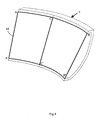
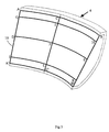
- the thin film is initially a sheet, the shape of which is part of the frustum of a cone laid flat.
- the thin film is applied with no initial tension to the suction chamber.
- Tension in the thin film is introduced when suction or differential pressure is applied and the thin film is drawn back into the suction chamber.
- An ideal shape will be achieved when the tensions in the thin film are close to uniform over the entire surface.
- Tensions at any point in the thin film can be considered as a combination of a vertical component and a horizontal component. Vertical tensions can be seen to be uniform, since at all points around the suction chamber, the thin film transitions from a chord to an arc as the thin film is drawn back into the suction chamber.
- the present invention provides apparatus for constructing a thin film mirror, which apparatus comprises a suction chamber, first attachment means positioned at a first side of the suction chamber and for attaching the thin film to the first side of the suction chamber, and second attachment means positioned at a second and opposite side of the suction chamber and for attaching the thin film to the second side of the suction chamber, wherein the first and second attachment means are such that they secure the thin film against movement when tension is applied in a first direction extending between the first and second attachment means; the first and second attachment means are such that they allow the thin film to move and stretch in a second direction which is at right angles to the first direction and which allows the thin film to be distorted to a desired geometric shape for forming the thin film mirror; the first attachment means comprises a flexible retaining strip, and adhesive means which secures the thin film wound around the flexible retaining strip to itself, and an attachment member which has first and second ends, the first end being such that it passes partially around the flexible retaining strip, and the second end being such that it is secured to
- the apparatus of the invention may include first adjustment means positioned at a third side of the suction chamber, and second adjustment means positioned at a fourth and opposite side of the suction chamber, the first and second adjustment means being for stretching the thin film in the second direction.
- the first adjustment means may comprise a clamping device for clamping the thin film, and tensioner means for applying a tension to the thin film in order to stretch the thin film in the second direction.
- the apparatus of the invention may be one in which the first side of the suction chamber is an upper side, In which the second side of the suction chamber is the lower side, in which the first direction in which the tension is applied is then a vertical direction, and in which the second direction in which the tension is applied is then a horizontal direction.
- the second attachment means is such that the flexible retaining strip of the second attachment means is of a circular cross section, and In which the first end of the attachment member of the second attachment means is concave, and the second end of the attachment member is straight
- the flexible retaining strip may be of other cross sectional shapes if desired. Generally, the first end of the attachment member will follow the profile of the flexible retaining strip.
- first and second attachment means will be of the same construction, but they may be of a different construction if desired.
- the first and second attachment means 6, 12 are such that they secure the thin film against movement when tension is applied in a first direction extending between the first and second attachment means 6, 12.
- the first and second attachment means 6, 12 are also such that they allow the thin film to move and stretch in a second direction which is at right angles to the first direction, and which allows the thin film 10 to be distorted to a desired geometric shape for forming the thin film mirror.
- the first side 8 of the suction chamber 4 is an upper side
- the second side 14 of the suction chamber 4 is a lower side.
- first direction in which the tension is applied to the thin film 10 is a vertical direction.
- the second direction in which the tension is applied to the thin film 10 is then a horizontal direction.
- the adjustment means for applying the horizontal tension to the thin film 10 may be a manual means, or a mechanical means such for example as a hydraulic, pneumatic or other mechanical means.
- the same tension may be applied to the top and bottom edge of the thin film 10, or the tension may be applied such that it is different at the top edge than at the bottom edge.
- the tension may also be applied to an extent that is less than the yield point of the material of the thin film, to an extent that is at the yield point of the material of the thin film, or to an extent that is beyond the yield point of the material of the thin film 10.
Landscapes
- Physics & Mathematics (AREA)
- General Physics & Mathematics (AREA)
- Optics & Photonics (AREA)
- Engineering & Computer Science (AREA)
- Mechanical Engineering (AREA)
- Optical Elements Other Than Lenses (AREA)
- Mounting And Adjusting Of Optical Elements (AREA)
- Advancing Webs (AREA)
- Mirrors, Picture Frames, Photograph Stands, And Related Fastening Devices (AREA)
Claims (7)
- Appareil (2) pour construire un miroir à film mince, lequel appareil (2) comprend une chambre d'aspiration (4), un premier moyen de fixation (6) positionné sur un premier côté (8) de la chambre d'aspiration (4) et pour attacher le film mince (10) au premier côté (8) de la chambre d'aspiration (4) et un deuxième moyen de fixation (12) positionné sur un deuxième côté opposé (14) de la chambre d'aspiration (4) et pour attacher le film mince (10) au deuxième côté (14) de la chambre d'aspiration (4), dans lequel les premier et deuxième moyens de fixation (6, 12) sont tels qu'ils assurent le film mince (10) contre tout mouvement quand une tension est appliquée dans une première direction s'étendant entre les premier et deuxième moyens de fixation (6, 12), les premier et deuxième moyens de fixation (6, 12) sont tels qu'ils permettent au film mince (10) de bouger et de s'étirer dans une deuxième direction qui est à angles droits par rapport à la première direction et qui permet au film mince (10) d'être déformé en une forme géométrique voulue pour former le miroir à film mince, le premier moyen de fixation (6) comprend une bande de retenue flexible (26) et un moyen adhésif (36) qui arrime le film mince (10) enroulé autour de la bande de retenue flexible (26) à lui-même et un membre de fixation (28) qui a des première et deuxième extrémités (30, 32), la première extrémité (30) étant telle qu'elle passe partiellement autour de la bande de retenue flexible (26) et la deuxième extrémité (32) étant telle qu'elle est arrimée à la chambre d'aspiration (4), et le deuxième moyen de fixation (12) comprend une bande de retenue flexible (26) et un moyen adhésif (36) qui arrime le film mince (10) enroulé autour de la bande de retenue flexible (26) à lui-même et un membre de fixation (28) qui à des première et deuxième extrémités (30, 32), la première extrémité (30) étant telle qu'elle passe partiellement autour de la bande de retenue flexible (26) et la deuxième extrémité (32) étant telle qu'elle est arrimée à la chambre d'aspiration (4).
- Appareil (2) selon la revendication 1 et comprenant un premier moyen d'ajustement (16) positionné sur un troisième côté (18) de la chambre d'aspiration (4) et un deuxième moyen d'ajustement positionné sur un quatrième côté opposé (20) de la chambre d'aspiration (4), les premier et deuxième moyens d'ajustement étant destinés à étirer le film mince (10) dans la deuxième direction.
- Appareil (2) selon la revendication 2 dans lequel le premier moyen d'ajustement (16) comprend un moyen de serrage (22) pour serrer le film mince (10) et un moyen tendeur (24) pour appliquer une tension sur le film mince (10) afin d'étirer le film mince (10) dans la deuxième direction.
- Appareil (2) selon la revendication 2 ou la revendication 3 dans lequel le deuxième moyen d'ajustement comprend un moyen de serrage pour serrer le film mince (10) et un moyen tendeur pour appliquer une tension sur le film mince (10) afin d'étirer le film mince (10) dans la deuxième direction.
- Appareil (2) selon une quelconque des revendications précédentes, dans lequel le premier côté (8) de la chambre d'aspiration (4) est un côté supérieur, dans lequel le deuxième côté (14) de la chambre d'aspiration (4) est un côté inférieur, dans lequel la première direction dans laquelle la tension est appliquée est alors une tension verticale, et dans lequel la deuxième direction dans laquelle la tension est appliquée est alors une direction horizontale.
- Appareil (2) selon une quelconque des revendications précédentes, dans lequel la bande de retenue flexible (26) du premier moyen de fixation (6) est de section transversale circulaire, dans lequel la première extrémité (30) du membre de fixation (28) du premier moyen de fixation (6) est concave et dans lequel la deuxième extrémité (32) du membre de fixation (28) du premier moyen de fixation est droite.
- Appareil (2) selon une quelconque des revendications précédentes, dans lequel la bande de retenue flexible du deuxième moyen de fixation (12) est de section transversale circulaire, dans lequel la première extrémité (30) du membre de fixation (28) du deuxième moyen de fixation (12) est concave et dans lequel la deuxième extrémité (32) du membre de fixation (28) du deuxième moyen de fixation (12) est droite.
Applications Claiming Priority (2)
| Application Number | Priority Date | Filing Date | Title |
|---|---|---|---|
| GB0215049A GB2390173B (en) | 2002-06-28 | 2002-06-28 | Apparatus for constructing a thin film mirror |
| GB0215049 | 2002-06-28 |
Publications (2)
| Publication Number | Publication Date |
|---|---|
| EP1376193A1 EP1376193A1 (fr) | 2004-01-02 |
| EP1376193B1 true EP1376193B1 (fr) | 2006-03-22 |
Family
ID=9939520
Family Applications (1)
| Application Number | Title | Priority Date | Filing Date |
|---|---|---|---|
| EP03253788A Expired - Lifetime EP1376193B1 (fr) | 2002-06-28 | 2003-06-16 | Appareil de fabrication d'un miroir à membrane |
Country Status (6)
| Country | Link |
|---|---|
| US (1) | US6945659B2 (fr) |
| EP (1) | EP1376193B1 (fr) |
| AT (1) | ATE321289T1 (fr) |
| CA (1) | CA2433121C (fr) |
| DE (1) | DE60304121D1 (fr) |
| GB (1) | GB2390173B (fr) |
Cited By (1)
| Publication number | Priority date | Publication date | Assignee | Title |
|---|---|---|---|---|
| CN100582863C (zh) * | 2005-07-08 | 2010-01-20 | Seos有限公司 | 构造薄膜镜的方法 |
Families Citing this family (6)
| Publication number | Priority date | Publication date | Assignee | Title |
|---|---|---|---|---|
| EP2250526A4 (fr) * | 2008-01-14 | 2013-08-21 | Focal Point Energy Inc | Capteur solaire à membrane étirée avec bord d'appui |
| US9268069B2 (en) * | 2010-01-29 | 2016-02-23 | Thomas Boeman | Parabolic reflector |
| GB2478538B (en) * | 2010-03-09 | 2015-04-29 | Equipe Electronics Ltd | Method for extending field of vision in a collimated visual display system |
| GB2490527A (en) | 2011-05-04 | 2012-11-07 | Thales Holdings Uk Plc | Mirror and mirror shell moulding method |
| ES2625412T3 (es) | 2012-06-01 | 2017-07-19 | Esterline Belgium Bvba | Método y aparato para fabricar un espejo de lámina delgada |
| JP2014154589A (ja) * | 2013-02-05 | 2014-08-25 | Fujifilm Corp | 太陽光集光用反射鏡 |
Family Cites Families (26)
| Publication number | Priority date | Publication date | Assignee | Title |
|---|---|---|---|---|
| DE372114C (de) * | 1923-03-20 | Heinrich Eidmann O | Vorrichtung zum Geradelegen der Isolierrohre von elektrischen Leitungen | |
| US3031928A (en) * | 1959-02-13 | 1962-05-01 | Baird Atomic Inc | Control of flexible surfaces by means of a probe |
| US4162825A (en) * | 1977-08-05 | 1979-07-31 | Ford Aerospace & Communications Corp. | Method for adjusting the radius of curvature of a spherical mirror |
| US4173397A (en) * | 1977-11-30 | 1979-11-06 | The United States Of America As Represented By The Administrator Of The National Aeronautics And Space Administration | Solar concentrator |
| US4288146A (en) * | 1980-05-14 | 1981-09-08 | Lajet Energy Company | Curved reflector with adjustable focal length |
| US4422723A (en) * | 1981-08-11 | 1983-12-27 | Lajet Energy Company | Adjustable reflector with imperforate reflective membrane |
| US4548482A (en) * | 1983-04-12 | 1985-10-22 | Lajet Energy Company | Reflector with easily replaceable reflective membrane |
| GB8403274D0 (en) * | 1984-02-08 | 1984-03-14 | Univ Strathclyde | Optical mirrors |
| US4592717A (en) * | 1984-05-04 | 1986-06-03 | Mcdonnell Douglas Corporation | End retract device for completing spherically shaped reflective film |
| FR2584824B1 (fr) * | 1985-07-10 | 1987-09-25 | Commissariat Energie Atomique | Miroir deformable |
| GB2183059B (en) * | 1985-11-05 | 1989-09-27 | Michel Treisman | Suspension system for a flexible optical membrane |
| DE3721114A1 (de) * | 1986-11-13 | 1988-05-19 | Kleinwaechter Juergen | Membrankonzentrationsspiegel |
| DE3837317A1 (de) * | 1988-11-03 | 1990-05-10 | Philips Patentverwaltung | Kernresonanzspektroskopieverfahren und anordnung zur durchfuehrung des verfahrens |
| US5317261A (en) * | 1991-05-27 | 1994-05-31 | U.S. Philips Corporation | Volume-selective magnetic resonance imaging method and device |
| US5680262A (en) * | 1993-02-12 | 1997-10-21 | Cummins Power Generation, Inc. | Stretched membrane mirror and method of making same |
| GB9521948D0 (en) * | 1995-10-26 | 1996-01-03 | Thomson Training & Simulation | A reflector |
| GB9603646D0 (en) * | 1996-02-21 | 1996-04-17 | Seos Displays Ltd | A method of constructing a thin film mirror |
| JP3073183B2 (ja) * | 1997-09-16 | 2000-08-07 | 技術研究組合医療福祉機器研究所 | 磁気共鳴装置 |
| US6111408A (en) * | 1997-12-23 | 2000-08-29 | Numar Corporation | Nuclear magnetic resonance sensing apparatus and techniques for downhole measurements |
| US6111409A (en) * | 1998-03-02 | 2000-08-29 | Western Atlas International, Inc. | Nuclear magnetic reasonance fluid characterization apparatus and method for using with electric wireline formation testing instruments |
| US6104191A (en) * | 1998-03-17 | 2000-08-15 | General Electric Company | Quantitative in vivo spectroscopy using oversampling, waterline referencing, and prior knowledge fitting |
| US6113242A (en) * | 1999-01-15 | 2000-09-05 | The United States Of America As Represented By The Secretary Of The Air Force | Active edge controlled optical quality membrane mirror |
| US6472870B1 (en) * | 1999-02-23 | 2002-10-29 | M. Robin Bendall | Radiofrequency irradiation schemes and methods of design and display for use in performing nuclear magnetic resonance spectroscopy |
| JP3854010B2 (ja) * | 1999-05-20 | 2006-12-06 | 株式会社アマダエンジニアリングセンター | 曲率可変ミラーの曲率調整装置 |
| GB0016777D0 (en) * | 2000-07-07 | 2000-08-30 | Seos Displays Ltd | Improved film mirror |
| US6617169B2 (en) * | 2001-03-30 | 2003-09-09 | Mclean Hospital Corporation | Two-dimensional MR spectroscopy techniques |
-
2002
- 2002-06-28 GB GB0215049A patent/GB2390173B/en not_active Expired - Fee Related
-
2003
- 2003-06-16 AT AT03253788T patent/ATE321289T1/de not_active IP Right Cessation
- 2003-06-16 EP EP03253788A patent/EP1376193B1/fr not_active Expired - Lifetime
- 2003-06-16 DE DE60304121T patent/DE60304121D1/de not_active Expired - Lifetime
- 2003-06-23 CA CA2433121A patent/CA2433121C/fr not_active Expired - Fee Related
- 2003-06-23 US US10/601,400 patent/US6945659B2/en not_active Expired - Lifetime
Cited By (1)
| Publication number | Priority date | Publication date | Assignee | Title |
|---|---|---|---|---|
| CN100582863C (zh) * | 2005-07-08 | 2010-01-20 | Seos有限公司 | 构造薄膜镜的方法 |
Also Published As
| Publication number | Publication date |
|---|---|
| US20040264018A1 (en) | 2004-12-30 |
| DE60304121D1 (de) | 2006-05-11 |
| GB2390173A (en) | 2003-12-31 |
| CA2433121A1 (fr) | 2003-12-28 |
| EP1376193A1 (fr) | 2004-01-02 |
| ATE321289T1 (de) | 2006-04-15 |
| GB2390173B (en) | 2005-03-23 |
| US6945659B2 (en) | 2005-09-20 |
| CA2433121C (fr) | 2012-02-28 |
| GB0215049D0 (en) | 2002-08-07 |
Similar Documents
| Publication | Publication Date | Title |
|---|---|---|
| EP1376193B1 (fr) | Appareil de fabrication d'un miroir à membrane | |
| JPH07102377B2 (ja) | 軸方向に移動可能なロールを備えたロールスタンド | |
| US20110261450A1 (en) | Projection apparatuses and associated methods | |
| EP0857310B1 (fr) | Reflecteur | |
| US11712713B2 (en) | Method of slot die coating over deformable back-up roll | |
| JPH09504881A (ja) | 光学的に補正した反射映像を作るビューイングアッセンブリ | |
| US8197076B2 (en) | Magnetic membrane mirror | |
| US6758569B2 (en) | Method of constructing a thin film mirror | |
| US6050692A (en) | Method of constructing a thin film mirror | |
| CA2611922C (fr) | Procede de construction d'un miroir a film mince | |
| CA1296209C (fr) | Miroirs | |
| JP2004321915A (ja) | 塗布方法及び塗布装置 | |
| EP0151584A1 (fr) | Lentilles correctrices en plastique fin pour systemes optiques | |
| CN211180355U (zh) | 预应力可调节的薄膜夹持机构 | |
| JPH03295618A (ja) | カレンダ特にパッキンシート製造用カレンダ | |
| US6332687B1 (en) | Plunger controlled, near-parabolic optical membrane mirror | |
| US20230252915A1 (en) | Display device | |
| CA2220148A1 (fr) | Procede et dispositif pour mesurer et corriger le profil de tension de lames de scies | |
| US6420823B1 (en) | Shadow mask structure and color CRT | |
| JP3341229B2 (ja) | フィルム、シート類の展張支持治具 | |
| SU833656A2 (ru) | Способ полимерной склейки силикатно-ОРгАНичЕСКиХ ТРиплЕКСОВ и блОКОВ | |
| JPS63112024A (ja) | テンシヨンレベラの平坦度矯正装置 | |
| JPS6393430A (ja) | テンシヨンレベラの平坦度矯正装置 | |
| JPH0834045A (ja) | 熱可塑性合成樹脂から薄膜及び板を製造するための押出プレス用幅広シート押出ダイ金型 | |
| ITTO940078A1 (it) | Procedimento per la correzione del timbro e per la regolazione della prontezza di emissione sonda di un'ancia, e mezzi per la realizzazione |
Legal Events
| Date | Code | Title | Description |
|---|---|---|---|
| PUAI | Public reference made under article 153(3) epc to a published international application that has entered the european phase |
Free format text: ORIGINAL CODE: 0009012 |
|
| AK | Designated contracting states |
Kind code of ref document: A1 Designated state(s): AT BE BG CH CY CZ DE DK EE ES FI FR GB GR HU IE IT LI LU MC NL PT RO SE SI SK TR |
|
| AX | Request for extension of the european patent |
Extension state: AL LT LV MK |
|
| 17P | Request for examination filed |
Effective date: 20040429 |
|
| 17Q | First examination report despatched |
Effective date: 20040603 |
|
| AKX | Designation fees paid |
Designated state(s): AT BE BG CH CY CZ DE DK EE ES FI FR GB GR HU IE IT LI LU MC NL PT RO SE SI SK TR |
|
| RBV | Designated contracting states (corrected) |
Designated state(s): AT BE BG CH CY CZ DE DK EE ES FI FR GR HU IE IT LI LU MC NL PT RO SE SI SK TR |
|
| GRAP | Despatch of communication of intention to grant a patent |
Free format text: ORIGINAL CODE: EPIDOSNIGR1 |
|
| GRAS | Grant fee paid |
Free format text: ORIGINAL CODE: EPIDOSNIGR3 |
|
| GRAA | (expected) grant |
Free format text: ORIGINAL CODE: 0009210 |
|
| AK | Designated contracting states |
Kind code of ref document: B1 Designated state(s): AT BE BG CH CY CZ DE DK EE ES FI FR GR HU IE IT LI LU MC NL PT RO SE SI SK TR |
|
| PG25 | Lapsed in a contracting state [announced via postgrant information from national office to epo] |
Ref country code: IT Free format text: LAPSE BECAUSE OF FAILURE TO SUBMIT A TRANSLATION OF THE DESCRIPTION OR TO PAY THE FEE WITHIN THE PRESCRIBED TIME-LIMIT;WARNING: LAPSES OF ITALIAN PATENTS WITH EFFECTIVE DATE BEFORE 2007 MAY HAVE OCCURRED AT ANY TIME BEFORE 2007. THE CORRECT EFFECTIVE DATE MAY BE DIFFERENT FROM THE ONE RECORDED. Effective date: 20060322 Ref country code: NL Free format text: LAPSE BECAUSE OF FAILURE TO SUBMIT A TRANSLATION OF THE DESCRIPTION OR TO PAY THE FEE WITHIN THE PRESCRIBED TIME-LIMIT Effective date: 20060322 Ref country code: AT Free format text: LAPSE BECAUSE OF FAILURE TO SUBMIT A TRANSLATION OF THE DESCRIPTION OR TO PAY THE FEE WITHIN THE PRESCRIBED TIME-LIMIT Effective date: 20060322 Ref country code: LI Free format text: LAPSE BECAUSE OF FAILURE TO SUBMIT A TRANSLATION OF THE DESCRIPTION OR TO PAY THE FEE WITHIN THE PRESCRIBED TIME-LIMIT Effective date: 20060322 Ref country code: CH Free format text: LAPSE BECAUSE OF FAILURE TO SUBMIT A TRANSLATION OF THE DESCRIPTION OR TO PAY THE FEE WITHIN THE PRESCRIBED TIME-LIMIT Effective date: 20060322 Ref country code: SI Free format text: LAPSE BECAUSE OF FAILURE TO SUBMIT A TRANSLATION OF THE DESCRIPTION OR TO PAY THE FEE WITHIN THE PRESCRIBED TIME-LIMIT Effective date: 20060322 Ref country code: RO Free format text: LAPSE BECAUSE OF FAILURE TO SUBMIT A TRANSLATION OF THE DESCRIPTION OR TO PAY THE FEE WITHIN THE PRESCRIBED TIME-LIMIT Effective date: 20060322 Ref country code: SK Free format text: LAPSE BECAUSE OF FAILURE TO SUBMIT A TRANSLATION OF THE DESCRIPTION OR TO PAY THE FEE WITHIN THE PRESCRIBED TIME-LIMIT Effective date: 20060322 |
|
| REG | Reference to a national code |
Ref country code: CH Ref legal event code: EP |
|
| REG | Reference to a national code |
Ref country code: IE Ref legal event code: FG4D |
|
| REF | Corresponds to: |
Ref document number: 60304121 Country of ref document: DE Date of ref document: 20060511 Kind code of ref document: P |
|
| PG25 | Lapsed in a contracting state [announced via postgrant information from national office to epo] |
Ref country code: IE Free format text: LAPSE BECAUSE OF NON-PAYMENT OF DUE FEES Effective date: 20060616 |
|
| PG25 | Lapsed in a contracting state [announced via postgrant information from national office to epo] |
Ref country code: BG Free format text: LAPSE BECAUSE OF FAILURE TO SUBMIT A TRANSLATION OF THE DESCRIPTION OR TO PAY THE FEE WITHIN THE PRESCRIBED TIME-LIMIT Effective date: 20060622 Ref country code: DK Free format text: LAPSE BECAUSE OF FAILURE TO SUBMIT A TRANSLATION OF THE DESCRIPTION OR TO PAY THE FEE WITHIN THE PRESCRIBED TIME-LIMIT Effective date: 20060622 Ref country code: SE Free format text: LAPSE BECAUSE OF FAILURE TO SUBMIT A TRANSLATION OF THE DESCRIPTION OR TO PAY THE FEE WITHIN THE PRESCRIBED TIME-LIMIT Effective date: 20060622 |
|
| PG25 | Lapsed in a contracting state [announced via postgrant information from national office to epo] |
Ref country code: DE Free format text: LAPSE BECAUSE OF FAILURE TO SUBMIT A TRANSLATION OF THE DESCRIPTION OR TO PAY THE FEE WITHIN THE PRESCRIBED TIME-LIMIT Effective date: 20060623 |
|
| PG25 | Lapsed in a contracting state [announced via postgrant information from national office to epo] |
Ref country code: MC Free format text: LAPSE BECAUSE OF NON-PAYMENT OF DUE FEES Effective date: 20060630 |
|
| PG25 | Lapsed in a contracting state [announced via postgrant information from national office to epo] |
Ref country code: ES Free format text: LAPSE BECAUSE OF FAILURE TO SUBMIT A TRANSLATION OF THE DESCRIPTION OR TO PAY THE FEE WITHIN THE PRESCRIBED TIME-LIMIT Effective date: 20060703 |
|
| PG25 | Lapsed in a contracting state [announced via postgrant information from national office to epo] |
Ref country code: PT Free format text: LAPSE BECAUSE OF FAILURE TO SUBMIT A TRANSLATION OF THE DESCRIPTION OR TO PAY THE FEE WITHIN THE PRESCRIBED TIME-LIMIT Effective date: 20060822 |
|
| NLV1 | Nl: lapsed or annulled due to failure to fulfill the requirements of art. 29p and 29m of the patents act | ||
| REG | Reference to a national code |
Ref country code: CH Ref legal event code: PL |
|
| ET | Fr: translation filed | ||
| PLBE | No opposition filed within time limit |
Free format text: ORIGINAL CODE: 0009261 |
|
| STAA | Information on the status of an ep patent application or granted ep patent |
Free format text: STATUS: NO OPPOSITION FILED WITHIN TIME LIMIT |
|
| 26N | No opposition filed |
Effective date: 20061227 |
|
| PG25 | Lapsed in a contracting state [announced via postgrant information from national office to epo] |
Ref country code: CZ Free format text: LAPSE BECAUSE OF FAILURE TO SUBMIT A TRANSLATION OF THE DESCRIPTION OR TO PAY THE FEE WITHIN THE PRESCRIBED TIME-LIMIT Effective date: 20060322 Ref country code: GR Free format text: LAPSE BECAUSE OF FAILURE TO SUBMIT A TRANSLATION OF THE DESCRIPTION OR TO PAY THE FEE WITHIN THE PRESCRIBED TIME-LIMIT Effective date: 20060623 |
|
| PG25 | Lapsed in a contracting state [announced via postgrant information from national office to epo] |
Ref country code: FI Free format text: LAPSE BECAUSE OF FAILURE TO SUBMIT A TRANSLATION OF THE DESCRIPTION OR TO PAY THE FEE WITHIN THE PRESCRIBED TIME-LIMIT Effective date: 20060322 Ref country code: EE Free format text: LAPSE BECAUSE OF FAILURE TO SUBMIT A TRANSLATION OF THE DESCRIPTION OR TO PAY THE FEE WITHIN THE PRESCRIBED TIME-LIMIT Effective date: 20060322 |
|
| PG25 | Lapsed in a contracting state [announced via postgrant information from national office to epo] |
Ref country code: LU Free format text: LAPSE BECAUSE OF NON-PAYMENT OF DUE FEES Effective date: 20060616 Ref country code: TR Free format text: LAPSE BECAUSE OF FAILURE TO SUBMIT A TRANSLATION OF THE DESCRIPTION OR TO PAY THE FEE WITHIN THE PRESCRIBED TIME-LIMIT Effective date: 20060322 Ref country code: HU Free format text: LAPSE BECAUSE OF FAILURE TO SUBMIT A TRANSLATION OF THE DESCRIPTION OR TO PAY THE FEE WITHIN THE PRESCRIBED TIME-LIMIT Effective date: 20060923 |
|
| PG25 | Lapsed in a contracting state [announced via postgrant information from national office to epo] |
Ref country code: CY Free format text: LAPSE BECAUSE OF FAILURE TO SUBMIT A TRANSLATION OF THE DESCRIPTION OR TO PAY THE FEE WITHIN THE PRESCRIBED TIME-LIMIT Effective date: 20060322 |
|
| BECH | Be: change of holder |
Owner name: ROCKWELL COLLINS UK LTD Effective date: 20120302 |
|
| REG | Reference to a national code |
Ref country code: FR Ref legal event code: CD Owner name: ROCKWELL COLLINS VISUAL DISPLAY SYSTEMS LIMITED Effective date: 20130603 |
|
| REG | Reference to a national code |
Ref country code: FR Ref legal event code: TP Owner name: ROCKWELL COLLINS UK LIMITED, GB Effective date: 20131007 |
|
| REG | Reference to a national code |
Ref country code: FR Ref legal event code: TP Owner name: ROCKWELL COLLINS, INC., US Effective date: 20150116 |
|
| REG | Reference to a national code |
Ref country code: FR Ref legal event code: PLFP Year of fee payment: 14 |
|
| PGFP | Annual fee paid to national office [announced via postgrant information from national office to epo] |
Ref country code: FR Payment date: 20160628 Year of fee payment: 14 Ref country code: BE Payment date: 20160627 Year of fee payment: 14 |
|
| REG | Reference to a national code |
Ref country code: FR Ref legal event code: ST Effective date: 20180228 |
|
| PG25 | Lapsed in a contracting state [announced via postgrant information from national office to epo] |
Ref country code: FR Free format text: LAPSE BECAUSE OF NON-PAYMENT OF DUE FEES Effective date: 20170630 |
|
| REG | Reference to a national code |
Ref country code: BE Ref legal event code: MM Effective date: 20170630 Ref country code: BE Ref legal event code: PD Owner name: ROCKWELL COLLINS, INC.; US Free format text: DETAILS ASSIGNMENT: CHANGE OF OWNER(S), AFFECTATION / CESSION; FORMER OWNER NAME: ROCKWELL COLLINS UK LIMITED Effective date: 20160628 |
|
| PG25 | Lapsed in a contracting state [announced via postgrant information from national office to epo] |
Ref country code: BE Free format text: LAPSE BECAUSE OF NON-PAYMENT OF DUE FEES Effective date: 20170630 |