EP1376202B1 - Oberflächenmodellierung einer ophtalmologischen Linse - Google Patents
Oberflächenmodellierung einer ophtalmologischen Linse Download PDFInfo
- Publication number
- EP1376202B1 EP1376202B1 EP02291502.9A EP02291502A EP1376202B1 EP 1376202 B1 EP1376202 B1 EP 1376202B1 EP 02291502 A EP02291502 A EP 02291502A EP 1376202 B1 EP1376202 B1 EP 1376202B1
- Authority
- EP
- European Patent Office
- Prior art keywords
- prescription
- point
- lens
- complex
- prism
- Prior art date
- Legal status (The legal status is an assumption and is not a legal conclusion. Google has not performed a legal analysis and makes no representation as to the accuracy of the status listed.)
- Expired - Lifetime
Links
- 238000000034 method Methods 0.000 claims description 22
- 239000000463 material Substances 0.000 claims description 5
- 208000001491 myopia Diseases 0.000 description 12
- 230000000750 progressive effect Effects 0.000 description 12
- 238000005259 measurement Methods 0.000 description 10
- 239000008188 pellet Substances 0.000 description 10
- 238000004364 calculation method Methods 0.000 description 9
- 230000003287 optical effect Effects 0.000 description 8
- 239000003550 marker Substances 0.000 description 7
- 230000006870 function Effects 0.000 description 6
- 239000011521 glass Substances 0.000 description 6
- 238000005457 optimization Methods 0.000 description 6
- 201000009310 astigmatism Diseases 0.000 description 5
- 238000003754 machining Methods 0.000 description 4
- 238000000354 decomposition reaction Methods 0.000 description 3
- 241001415961 Gaviidae Species 0.000 description 2
- 229920000297 Rayon Polymers 0.000 description 2
- 241001080024 Telles Species 0.000 description 2
- 230000004075 alteration Effects 0.000 description 2
- 238000013459 approach Methods 0.000 description 2
- 230000008901 benefit Effects 0.000 description 2
- 230000008569 process Effects 0.000 description 2
- 210000001747 pupil Anatomy 0.000 description 2
- 239000002964 rayon Substances 0.000 description 2
- 238000012360 testing method Methods 0.000 description 2
- KRQUFUKTQHISJB-YYADALCUSA-N 2-[(E)-N-[2-(4-chlorophenoxy)propoxy]-C-propylcarbonimidoyl]-3-hydroxy-5-(thian-3-yl)cyclohex-2-en-1-one Chemical compound CCC\C(=N/OCC(C)OC1=CC=C(Cl)C=C1)C1=C(O)CC(CC1=O)C1CCCSC1 KRQUFUKTQHISJB-YYADALCUSA-N 0.000 description 1
- 208000029091 Refraction disease Diseases 0.000 description 1
- 230000006978 adaptation Effects 0.000 description 1
- 230000004430 ametropia Effects 0.000 description 1
- 230000008859 change Effects 0.000 description 1
- 238000013461 design Methods 0.000 description 1
- 238000011156 evaluation Methods 0.000 description 1
- 238000012067 mathematical method Methods 0.000 description 1
- 230000008447 perception Effects 0.000 description 1
- 201000010041 presbyopia Diseases 0.000 description 1
- 238000012545 processing Methods 0.000 description 1
- 208000014733 refractive error Diseases 0.000 description 1
- 239000011265 semifinished product Substances 0.000 description 1
Images

Classifications
-
- G—PHYSICS
- G02—OPTICS
- G02C—SPECTACLES; SUNGLASSES OR GOGGLES INSOFAR AS THEY HAVE THE SAME FEATURES AS SPECTACLES; CONTACT LENSES
- G02C7/00—Optical parts
- G02C7/02—Lenses; Lens systems ; Methods of designing lenses
- G02C7/06—Lenses; Lens systems ; Methods of designing lenses bifocal; multifocal ; progressive
- G02C7/061—Spectacle lenses with progressively varying focal power
-
- G—PHYSICS
- G02—OPTICS
- G02C—SPECTACLES; SUNGLASSES OR GOGGLES INSOFAR AS THEY HAVE THE SAME FEATURES AS SPECTACLES; CONTACT LENSES
- G02C7/00—Optical parts
- G02C7/02—Lenses; Lens systems ; Methods of designing lenses
- G02C7/06—Lenses; Lens systems ; Methods of designing lenses bifocal; multifocal ; progressive
- G02C7/061—Spectacle lenses with progressively varying focal power
- G02C7/063—Shape of the progressive surface
Definitions
- the present invention relates to ophthalmic lenses, and more specifically to the modeling of a complex surface of a lens, for example a progressive multifocal surface. It applies in particular to the calculation of a prescription surface, spherical or toric, of an ophthalmic lens.
- Multifocal ophthalmic lenses are well known; these multifocal lenses can be distinguished from lenses called progressive lenses, and lenses specifically dedicated to near vision.
- Progressive multifocal ophthalmic lenses are used to correct presbyopia and allow the wearer to view objects in a wide range of distances, without having to remove his glasses.
- Such lenses typically include a far vision zone, located in the top of the lens, a near vision zone, located in the bottom of the lens, an intermediate zone connecting the near vision zone and the vision zone. by far, as well as a main meridian of progression crossing these three zones.
- a reference point for far vision in the far vision zone and a point of reference for near vision in the near vision zone is provided.
- lenses are for example described in FR-A-2,699,294 , US-A-5,270,745 , US-A-5,272,495 , FR-A-2,683,642 , FR-A-2,699,294 or FR-A-2,704,327 .
- lenses specifically dedicated to near vision do not have a far vision zone with a reference point defined as in conventional progressive lenses. These lenses are prescribed according to the power required by the wearer in near vision, regardless of the power in far vision. This type of lens is described in an article by the Optician Lunetier of April 1988, and is marketed by the plaintiff under the brand Essilor Interview. This lens is also described in FR-A-2,588,973 .
- multifocal lenses comprise an aspheric multifocal face, for example the face opposite to the wearer of the glasses, and a spherical or toric face, called the prescription face.
- This spherical or toric surface makes it possible to adapt the lens to the ametropia of the user, prescribed by the ophthalmologist.
- a multifocal lens is therefore generally a semi-finished product, which must be adapted to the wearer by machining the prescription face.
- Such a multifocal lens can be defined by providing hundreds of parameters defining the altitude of a large number of points of the surface.
- EP-A-0 990 939 A method of adapting the spherical or toric face is described in detail in EP-A-0 990 939 ; it is proposed to use to define the back side a ray tracing program and proceed by optimization.
- the face before is modeled by Zemike polynomials.
- EP-A-0 990 939 also mentions that an aspherical surface is generally defined by the altitude of all the points of the surface, or by the values of mean sphere and cylinder at all points of the surface.
- the sphere and the cylinder at a point being classically defined as the half-sum and the difference of the maximum and minimum curvatures of the surface at this point, multiplied by a factor (n-1), with n the refractive index of the material of the lens.
- US-A-5,444,503 proposes to define the prescription surface of the lens from the aberrations over the entire surface of the lens, by appropriately varying a parameterized continuous surface, for example a surface defined by splines, using mathematical algorithms known optimization.
- US-A-6,089,713 discloses a lens having a spherical or aspherical front having rotational symmetry.
- the rear face is adapted to the wearer, to impart to the lens the sphere, the astigmatism and the prescribed prism, and their distribution on the lens.
- the multifocal surface is defined for each user.
- US-A-2,878,721 offers a multifocal lens, with a prescription face on the front of the lens.
- the prescription face is used to adapt the lens to the user, without the nature of this adaptation being specified.
- An object of the invention in certain embodiments, is to model the complex surface of a lens, precisely and simply at a point or around a point, in order to be able to calculate powers at this point, in different configurations. , without it being necessary to know in an exhaustive way the geometry of the complex surface of the lens.
- local features around the prescription point include local features in a pellet centered on the prescription point and of diameter greater than or equal to 2 mm.
- Local features around the prescription point may also be provided with local features in a pellet centered on the prescription point and less than or equal to 12 mm in diameter.
- local features around the prescription point may be expected to include local features in a pellet centered on the prescription point and not covering the prism reference point.
- local features at the prescription point may include normal and major curvatures with their orientations at that point in a given landmark.
- the invention proposes a modeling of a complex surface or of a lens having a complex surface, which is of a nature to allow all the usual operations in a prescription laboratory - in particular the calculation of a prescription surface.
- the modeling of the invention avoids having to know all the characteristics of the complex surface of the lens.
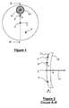
- the figure 1 shows a view of the complex surface of a lens.
- a semi-finished lens of circular shape which typically has a diameter of 60 mm.
- a point of the lens is used by the prescription laboratory for prism referral; it is usually the center of the lens, reference 2 in the figure.
- the prism reference point is usually materialized on the lens by a visible mark.
- the prism reference point is used by the prescription laboratory to adapt the lens to the prism prescribed to the wearer by the ophthalmologist.
- the lens also has a point used for calculating or measuring the characteristics prescribed to the wearer: it may be a power, in the absence of prescription of astigmatism to the wearer. It can also be a power, a cylinder and an axis, if the wearer is assigned an astigmatism that must be corrected. Such a prescription amounts to providing two powers and one axis. In the following, we use the words "point of prescription" to designate this point of the lens.
- the reference point for far vision is usually used as a prescription point.
- the point of reference for near vision 6 is used as a prescription point: in this case, the prescription is that proposed by the ophthalmologist in near vision.
- the reference point for near vision is used as the prescription point.
- the figure shows the case of a progressive multifocal lens, with reference point 4 for distance vision; as in the lenses marketed by the plaintiff, this point is 8 mm above the center of the lens.
- the "characteristic points" of the lens are called the prism reference point (PRP) and the prescription point - whether it is the reference point for distance vision or the point of reference for vision. closely, or from another point on the lens.
- PRP prism reference point
- the lens also conventionally presents a mounting cross 8. This is a point that is materialized on the surface of the lens and is used by the optician for mounting the lens in the frame. In the Applicant's lenses, this point is located four millimeters above the PRP. This point is not a "characteristic point" in the sense of the present description but is useful for positioning the lens in front of the eye of the wearer.
- the elements forming the modeling can be expressed in an orthonormal reference system whose origin is the prism reference point, whose axis x has the same direction as the normal to the complex surface at this point and whose axis z is given by the tangent to the complex surface at the prism reference point contained in a horizontal plane in the use position of the lens, the y axis is then the orthogonal axis to the two previous ones.
- the figure shows the x and y axes.
- the marker could also be defined by indicating that the y and z axes are tangent to the complex surface at the prism reference point and correspond to the orientation of the lens during its use.
- the vertical is defined by the center of the lens (which is also the prism reference point) and by the mounting cross, both of which are materialized on the lens.
- the reference simply by indicating that the plane (y, z) is tangent to the lens at the prism reference point and that the plane (x, y) contains the mounting cross.
- the provision of the prism reference point, the prescription point and the normal to the complex surface at the prism reference point makes it possible to position the complex surface of the lens and to direct a ray toward the prescription point.
- Local characteristics of the surface are provided at or around the prescription point.
- the above-mentioned reference, centered on the prism reference point, or a marker centered on the prescription point can be used to provide these characteristics. If we use a second marker, centered on the prescription point, we can ensure that the plane tangent to the prescription point is the plane (y, z) of this second marker; however, it is necessary to know the directions of the axes of the second marker in the first marker, so that a marker change can be made freely.
- these can be the first and second derivatives of the surface at the prescription point - which represents five coefficients.
- Local features around the prescription point may be provided in a circular pellet 10, the center of which is the prescription point and which extends over the complex surface around the prescription point; the diameter of the pellet is greater than or equal to two millimeters, so as to provide the characteristics of the surface at least in the immediate vicinity of the prescription point.
- the diameter of the pellet is less than or equal to 12 mm - this size being sufficient for modeling the complex surface and limiting the amount of information needed to model the surface.
- the size of the pellet could be limited so that it does not cover two characteristic points of the lens: in this case, the pellet extends around the prescription point - point VL or VP point - and does not include the prism reference point.
- the local characteristics of the complex surface can be provided in one or the other of the aforementioned landmarks in different forms. It is thus possible to provide an altitude map of the different points of the complex surface; it is also possible to provide a representation of the complex surface by polynomial decomposition, for example using families of polynomials available in commercial surface calculation software. For example, in the case of Zemike polynomials (or other polynomials), order 3 decomposition can be used, for a 2 mm tablet diameter or up to 5 for a tablet diameter. 10 mm or more.
- Tests carried out by the Applicant recommend the use of Zemike polynomials of up to a degree 5 for a pupil diameter ranging from 8 mm to 12 mm, a degree 4 for a diameter ranging from 3 mm to 7 mm and a degree 3 for a diameter. strictly less than 3mm.
- the thickness of the lens is measured along a given axis at a given point; this is usually the prism reference point and the normal to the front surface at this point.
- the tangent plane of the other surface of the lens is given, for example at the intersection of the lens with the axis along which the thickness is measured.
- the tangent plane can be given by simply providing the normal unit vector to the other surface of the lens at the point of intersection with the axis.
- the curvatures and their orientations of the other surface of the lens can be given directly or indirectly by the data of a prescription in a given configuration. In the latter case the curvatures and their orientations are calculated in order to satisfy the given prescription.
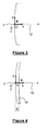
- the figure 2 shows a sectional view of a complex lens, in a vertical plane.
- the figure has been made of the prism reference point, the prescription point and the complex surface pellet, referenced as on the figure 1 .
- the complex surface has a normal prism reference point coincident with the x-axis of the lens.
- the thickness e is measured along the x axis; the normal vector 12 defining the plane tangent to the prescription surface on the x-axis has also been worn.
- the lens modeling thus proposed can be used in particular for the calculation of prescription, as indicated below.
- the first step involves associating with the complex face of this semi-finished lens a reference R, whose origin is at the prism reference point and whose axis x is normal to the complex face at this point.
- the y and z axes pass through the PRP and are in the plane tangent to the complex surface at this point.
- the y-axis passes through the PRP and the point which is the orthogonal projection along the x-axis of the mounting cross on the tangent plane to the complex surface at the PRP.
- the z axis is orthogonal to the other two and whose direction is chosen to obtain a direct reference.
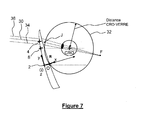
- the figure 3 shows this mark and a section of the complex face in the plane (PRP, x, y).
- the thickness of the lens may be chosen according to the power prescribed to the wearer, or depending on the mounting constraints in the frame.
- the thickness as shown in the following description, no longer varies in the proposed method: it can therefore be equal to the thickness along the axis of the adapted lens.
- the figure 5 shows a third step of the process.
- the starting prescription surface is turned, to obtain the desired prism, while keeping the thickness in the center fixed. In the example of the figure, it is a rotation about the axis z, in the forward direction. More generally, the inclination is provided by the prism prescribed to the wearer by the ophthalmologist; the inclination of the prescription surface is thus chosen so that the angle of the tangent plane at the x axis provides the prescribed prism. It is understood at this stage why the prism reference point of the complex surface is so called.
- the figure 6 shows the fourth step of the method which consists in positioning the lens consisting of the complex front face and the starting prescription face (with a thickness e and the prescribed prism) in the configuration configuration called carrier configuration.
- the initial lens must be positioned in front of the wearer's eye for which the lens is intended.
- Other configurations will be described later.
- This initial lens is placed in front of the eye so as to occupy the position it would have if it was actually mounted in the frame of the wearer. To do this, it is translated along the y axis so that the mounting cross is in front of the CRO, then rotated about the axis passing through the mounting and direction cross z by an angle equal to pantoscopic angle of the mount. We can proceed the same along the y axis to take into account the possible shape of the frame. Finally, the lens is translated along the axis 28 so that the distance between the CRO and the prescription face is that which exists between the wearer's CRO and the final lens once mounted in its frame and placed in front of the eye.
- lens mounting parameters are either provided by the manufacturer or estimated for an average wearer of a given population, as is known to those skilled in the art.
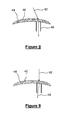
- the figure 7 shows a fifth step of the process.
- the radius or the radius, passing through the prescription point of the complex surface calculates the carrier power (s) obtained with the prescription surface considered. This calculation makes it possible to determine whether or not the prescribed prescription surface provides the prescribed powers. It is then possible to modify, if necessary, the prescription surface, as indicated below.
- the ray tracing can be carried out simply: the complex surface is known by modeling and in particular the local characteristics of the prescription surface at the prescription point or around it. At this stage, the ray pattern also assumes the index of the material forming the lens. The knowledge of the geometric characteristics of the prescription surface and the position of the prescription surface allow to continue the ray tracing through the lens.
- the carrier powers calculated during this fifth step - are equal to the inverse of a focusing distance. These distances need to define a reference.
- this reference is the so-called vertex sphere referenced 32 in the figure. Its center is the CRO and passes through the point of intersection of the horizontal axis 28 and the rear surface of the lens.
- the proximity of one of the focusing points is defined as the inverse 1 / JF of the distance JF between the point J of intersection of the radius 30 with the sphere of the vertices and the point F of focusing of the rays 30 and its neighbors considered.
- the power is defined as the proximity 1 / JF.
- wavefront it is equally possible to calculate, for a plane incident wavefront - ie for parallel rays - the shape of the wavefront after crossing the lens.
- the wavefront after crossing the lens then presents curvature values - major curvatures and angles, or sphere, cylinder and axis - that must be used to achieve the values prescribed by the ophthalmologist.
- the ray pattern passing through points adjacent to the prescription point does not require knowing the entire complex surface: it is sufficient to know the local characteristics of the surface, at the point of prescription - in the case of a single ray - or around it - in the case of a plurality of rays around a radius passing through the prescription point.
- the power calculation is thus possible without it being necessary to have information on the entire complex surface.
- the back surface is calculated in this step by a method of optimization or search of zero of a function; the nature of the optimization or that of the search for zero of a function is not detailed, insofar as it is possible to use various solutions known to those skilled in the art, such as the methods of Levenberg-Marquardt and Quasi-Newton for the optimization or the methods of Newton and Newton-Raphson for the search for the zero of a function.
- optimization consists in setting target values - the prescription values provided by the ophthalmologist - and varying the curvatures of the prescription surface so that the values obtained when calculating by ray tracing approach target values.
- the values of the powers obtained by the ray tracing are a function with real values of variables which are the curvatures of the prescription surface; in this case, the search for a prescription surface amounts to looking for the values of the curvatures for which the function has for values the values prescribed by the ophthalmologist.
- the mathematical problem is the search for zeros of a real-valued function of several real variables. This problem can be solved by the application of known mathematical methods.
- the use of a Newton method to ensure a carrier prescription requires from 2 to 4 iterations for a range of prescription spheres ranging from -2 to +2 diopters and a range of prescription cylinder ranging from -2 to +2 diopters.
- the invention provides all the information necessary for machining the prescription surface: the thickness at the center of the lens is fixed at the second step, the inclination of the surface of prescription is set in the third step, the positioning of the lens in front of the eye is provided in the fourth step, and the curvatures of the prescription surface are calculated in the fifth step. It is therefore possible to proceed with the machining of the prescription surface. As explained above, this calculation of the back surface was done without knowing the whole of the complex surface, but from local geometric features of the complex surface, at the point of prescription or around this point.
- a lensometer is a device, well known per se; the device has a tip, on which the lens is placed for measurement. The device provides indications of power, astigmatism and axis.
- the Figures 8 and 9 show schematic representations of a lens and the tip of a lensmeter, for the measurement of power in various configurations of lensometer.
- the figure 8 shows the lens 40, a ray 42 entering through the point to be measured on the front surface 44 of the lens, the tip 46 of the frontofocometer, and the radius after crossing the lens.
- the average radius of the beam exiting the tip is perpendicular to the surface in contact with the tip - in the example the rear surface.
- the figure 9 is analogous to the figure 8 ; however, in the configuration of the figure 9 , traditionally called IOA configuration ("infinity on axis"), the mean radius 42 enters the surface of the lens opposite to the tip being parallel to the axis of the tip, ie perpendicular to the surface in contact with the tip.
- IOA configuration finity on axis
- the figures of other radii and the point of focus have not been shown.
- the invention can be used to determine a prescription surface of a lens, so that the results of the power measurement, in one of the configurations mentioned, are equal to the prescriptions of the ophthalmologist.
- the power represents the proximity of the point of focus, after crossing the glass, of a beam of rays coming from infinity; this definition of the power has the advantage of corresponding to the definition of power for a thin lens approximation at the optical center.
- the rays in question can cross the glass in oblique incidence in a zone of the glass without axis of symmetry, where the local prism is non-zero and therefore in the presence of optical aberrations, it may be necessary to consider different configurations. to achieve exactly the prescribed power.
- opticians In practice, opticians often use a frontofocometer for power measurement. It is possible to determine the prescription area so that the measurement with the lensometer provides the power values prescribed by the ophthalmologist.
- the values prescribed by the ophthalmologist are the values obtained in the configuration of the figure 7 indeed, this corresponds better to the perception of the wearer of the lenses.
- the values measured with a lensmeter can be slightly different from the values prescribed by the ophthalmologist.
- the ray pattern allows the calculation of the results obtained in a measurement with a lensometer for such a surface. Providing these values to the optician enables him to verify, by a measurement on the lensometer, the machining of the prescription surface of the lens
- the present invention is not limited to the embodiments described by way of example.
- the case of lenses having a complex front surface and a back prescription surface has been considered; in other words, worn, the prescription surface is the closest surface of the wearer's eye.
- the invention also applies to the case of a prescription surface on the front of the lens, which is not described in detail in the examples.
Landscapes
- Health & Medical Sciences (AREA)
- Ophthalmology & Optometry (AREA)
- Physics & Mathematics (AREA)
- General Health & Medical Sciences (AREA)
- General Physics & Mathematics (AREA)
- Optics & Photonics (AREA)
- Eyeglasses (AREA)
Claims (7)
- Verfahren zur Modellierung einer komplexen Fläche einer ophthalmischen Linse, umfassend- die Bereitstellung von:- einem Prismenbezugspunkt (2) und einem Rezeptpunkt (4);- der Normalen (12) zur komplexen Fläche am Prismenbezugspunkt; und- lokaler Merkmale der komplexen Fläche am Rezeptpunkt oder um den Rezeptpunkt herum, wobei die lokalen Merkmale die Normale und die Hauptkrümmungen mit ihren Ausrichtungen an diesem Punkt in einem gegebenen Bezugssystem enthalten; und- die Modellierung der komplexen Fläche der Linse durch die lokalen Merkmale.
- Verfahren nach Anspruch 1, dadurch gekennzeichnet, dass die lokalen Merkmale um den Rezeptpunkt herum lokale Merkmale in einem Plättchen (10) enthalten, das auf den Rezeptpunkt zentriert ist und einen Durchmesser von mehr als oder gleich 2 mm hat.
- Verfahren nach Anspruch 1 oder 2, dadurch gekennzeichnet, dass die lokalen Merkmale um den Rezeptpunkt herum lokale Merkmale in einem Plättchen (10) enthalten, das auf den Rezeptpunkt zentriert ist und einen Durchmesser von weniger als oder gleich 12 mm hat.
- Verfahren nach Anspruch 1 oder 2, dadurch gekennzeichnet, dass die lokalen Merkmale um den Rezeptpunkt herum lokale Merkmale in einem Plättchen (10) enthalten, das auf den Rezeptpunkt zentriert ist und den Prismenbezugspunkt nicht abdeckt.
- Verfahren zum Modellieren einer eine erste und eine zweite sphärische oder torische Fläche aufweisenden Linse, umfassend die Bereitstellung:- einer Modellierung der ersten Fläche der Linse durch das Verfahren nach einem der Ansprüche 1 bis 4;- der Dicke der Linse am Prismenbezugspunkt (2) gemäß der von der Normalen definierten Achse;- der die zweite Fläche (14) der Linse auf der Achse tangierenden Ebene;- der Hauptkrümmungen und ihrer Ausrichtungen der zweiten Fläche; und- des Index des die Linse bildenden Materials.
- Verfahren zur Berechnung der Rezeptfläche einer halbfertigen Linse, die eine komplexe Fläche aufweist, umfassend:- die Bereitstellung eines Rezepts, das mindestens eine Stärke und ein Prisma enthält;- die Bereitstellung einer Modellierung der Linse durch das Verfahren des Anspruchs 5;- die Berechnung der sphärischen oder torischen Rezeptfläche (14) unter Verwendung eines Radiusverlaufs, der durch den Rezeptpunkt oder um den Rezeptpunkt herum geht.
- Verfahren nach Anspruch 6, dadurch gekennzeichnet, dass der Rechenschritt Folgendes umfasst:- die Bereitstellung einer Ausgangs-Rezeptfläche, die auf der von der Normalen definierten Achse das verschriebene Prisma aufweist;- die Veränderung der Krümmungen und ihrer Ausrichtungen der Ausgangs-Rezeptfläche, mit konstantem Prisma, damit die durch den Radiusverlauf berechneten Stärken sich den verschriebenen Stärken annähern.
Priority Applications (3)
| Application Number | Priority Date | Filing Date | Title |
|---|---|---|---|
| EP02291502.9A EP1376202B1 (de) | 2002-06-17 | 2002-06-17 | Oberflächenmodellierung einer ophtalmologischen Linse |
| ES02291502.9T ES2518927T3 (es) | 2002-06-17 | 2002-06-17 | Modelado de una superficie de una lente oftálmica |
| US10/459,157 US6789898B2 (en) | 2002-06-17 | 2003-06-11 | Model for representing an ophthalmic lens surface |
Applications Claiming Priority (1)
| Application Number | Priority Date | Filing Date | Title |
|---|---|---|---|
| EP02291502.9A EP1376202B1 (de) | 2002-06-17 | 2002-06-17 | Oberflächenmodellierung einer ophtalmologischen Linse |
Publications (2)
| Publication Number | Publication Date |
|---|---|
| EP1376202A1 EP1376202A1 (de) | 2004-01-02 |
| EP1376202B1 true EP1376202B1 (de) | 2014-08-13 |
Family
ID=29716940
Family Applications (1)
| Application Number | Title | Priority Date | Filing Date |
|---|---|---|---|
| EP02291502.9A Expired - Lifetime EP1376202B1 (de) | 2002-06-17 | 2002-06-17 | Oberflächenmodellierung einer ophtalmologischen Linse |
Country Status (3)
| Country | Link |
|---|---|
| US (1) | US6789898B2 (de) |
| EP (1) | EP1376202B1 (de) |
| ES (1) | ES2518927T3 (de) |
Families Citing this family (24)
| Publication number | Priority date | Publication date | Assignee | Title |
|---|---|---|---|---|
| JP3582527B1 (ja) * | 2003-04-10 | 2004-10-27 | セイコーエプソン株式会社 | 累進屈折力レンズ及び製造方法 |
| FR2866442B1 (fr) * | 2004-02-18 | 2006-08-04 | Essilor Int | Afficheur orphtalmique comportant une lentille optalmique et un imageur optique |
| ES2217987B1 (es) * | 2004-05-05 | 2005-10-16 | Indo Internacional S.A. | Procedimiento para el calculo de una lente oftalmica y lente correspondiente. |
| US6955433B1 (en) * | 2004-06-17 | 2005-10-18 | Johnson & Johnson Vision Care, Inc. | Methods for designing composite ophthalmic lens surfaces |
| EP1752815A1 (de) * | 2005-08-11 | 2007-02-14 | Essilor International (Compagnie Generale D'optique) | Methode zur Herstellung eines optischen Systems |
| DE112008000055A5 (de) * | 2007-01-25 | 2009-12-10 | Rodenstock Gmbh | Bezugspunkte für Orthostellung |
| DE112008000049A5 (de) * | 2007-01-25 | 2009-09-10 | Rodenstock Gmbh | Flexibler Gleitsichtglasoptimierer |
| WO2009135058A2 (en) * | 2008-04-30 | 2009-11-05 | Ophthonix, Inc. | Method of designing progressive addition lenses |
| US8157568B2 (en) * | 2008-05-22 | 2012-04-17 | Tsutomu Hara | Ophthalmologic model |
| FR2954196B1 (fr) * | 2009-12-21 | 2012-01-20 | Essilor Int | Procede d'usinage pour tournage d'une face d'un verre de lunettes |
| FR2979558B1 (fr) * | 2011-09-01 | 2013-10-04 | Essilor Int | Procede de surfacage d'une surface d'un verre de lunettes |
| US11327339B2 (en) | 2016-03-04 | 2022-05-10 | Essilor International | Method of ordering an ophthalmic lens and corresponding system |
| US10048512B2 (en) | 2016-10-08 | 2018-08-14 | eyeBrain, Medical, Inc. | Low-convergence spectacles |
| US10048511B2 (en) | 2016-10-08 | 2018-08-14 | eyeBrain, Medical, Inc. | Eye-strain reducing lens |
| US10338409B2 (en) | 2016-10-09 | 2019-07-02 | eyeBrain Medical, Inc. | Lens with off-axis curvature center |
| US20180196281A1 (en) | 2017-01-06 | 2018-07-12 | eyeBrain Medical, Inc. | Prismatic contact lens |
| US12569135B2 (en) | 2017-09-05 | 2026-03-10 | Newton, Inc. | Headset-based system for measuring binocular alignment |
| US11589745B2 (en) | 2017-09-05 | 2023-02-28 | Neurolens, Inc. | Method and system for measuring binocular alignment |
| US12114930B2 (en) | 2017-09-05 | 2024-10-15 | Neurolens, Inc. | System for measuring binocular alignment with adjustable displays and eye trackers |
| US10420467B2 (en) | 2017-09-05 | 2019-09-24 | eyeBrain Medical, Inc. | Method and system for measuring binocular alignment |
| US11360329B2 (en) | 2017-12-31 | 2022-06-14 | Neurolens, Inc. | Negative power eye-strain reducing lens |
| US10921614B2 (en) | 2017-12-31 | 2021-02-16 | Neurolens, Inc. | Low-convergence negative power spectacles |
| US10908434B2 (en) | 2018-01-01 | 2021-02-02 | Neurolens, Inc. | Negative power lens with off-axis curvature center |
| JP7452037B2 (ja) * | 2020-01-29 | 2024-03-19 | 株式会社ニデック | 眼鏡レンズ情報取得装置及び眼鏡レンズ情報取得プログラム |
Family Cites Families (10)
| Publication number | Priority date | Publication date | Assignee | Title |
|---|---|---|---|---|
| DE4012609A1 (de) * | 1990-04-19 | 1991-10-24 | Zeiss Carl Fa | Gleitsichtflaeche fuer eine gleitsichtbrillenlinse |
| FR2699294B1 (fr) * | 1992-12-11 | 1995-02-10 | Essilor Int | Lentille ophtalmique multifocale progressive. |
| US5636338A (en) * | 1993-01-29 | 1997-06-03 | Silicon Graphics, Inc. | Method for designing curved shapes for use by a computer |
| JP3196880B2 (ja) * | 1995-09-22 | 2001-08-06 | ホーヤ株式会社 | 累進多焦点レンズ |
| JP4425350B2 (ja) * | 1996-04-04 | 2010-03-03 | カール・ツァイス・ヴィジョン・オーストラリア・ホールディングス・リミテッド | プログレッシブレンズ要素及びその設計方法並びに使用方法 |
| DE29724752U1 (de) * | 1996-07-05 | 2004-03-11 | Rodenstock Gmbh | Progressives Brillenglas |
| FR2753805B1 (fr) * | 1996-09-20 | 1998-11-13 | Essilor Int | Jeu de lentilles ophtalmiques multifocales progressives |
| FR2783938B1 (fr) * | 1998-09-28 | 2000-11-17 | Essilor Int | Lentilles ophtalmiques toriques |
| FR2788861B1 (fr) * | 1999-01-22 | 2001-03-30 | Essilor Int | Lentille ophtalmique multifocale progressive |
| FR2820515B1 (fr) * | 2001-02-02 | 2003-05-16 | Essilor Int | Lentille ophtalmique multifocale progressive a variation de puissance rapide |
-
2002
- 2002-06-17 EP EP02291502.9A patent/EP1376202B1/de not_active Expired - Lifetime
- 2002-06-17 ES ES02291502.9T patent/ES2518927T3/es not_active Expired - Lifetime
-
2003
- 2003-06-11 US US10/459,157 patent/US6789898B2/en not_active Expired - Lifetime
Also Published As
| Publication number | Publication date |
|---|---|
| EP1376202A1 (de) | 2004-01-02 |
| ES2518927T3 (es) | 2014-11-05 |
| US20030231282A1 (en) | 2003-12-18 |
| US6789898B2 (en) | 2004-09-14 |
Similar Documents
| Publication | Publication Date | Title |
|---|---|---|
| EP1376202A1 (de) | Oberflächenmodellierung einer ophtalmologischen Linse | |
| EP0990939B1 (de) | Torische ophthalmische Linsen | |
| EP0927377B2 (de) | Serie progressiver ophtalmischer multifokaler linsen | |
| EP1791014B1 (de) | Ophthalmische Linse | |
| EP1272892B1 (de) | Verfahren zum montieren von ophthalmischen linsen | |
| EP3065620B1 (de) | Verfahren zur bestimmung mindestens eines optischen designparameters für eine progressive kontaktlinse | |
| EP2479599B1 (de) | Verfahren zur Bestimmung einer Sehlinse unter Verwendung einer unterschiedlichen Verschreibung für den Astigmatismus für Fern- und Nahsicht | |
| WO2010119183A1 (fr) | Procédé de détermination d'une lentille ophtalmique | |
| EP1783533B1 (de) | Ophthalmische Linse | |
| EP2387734B1 (de) | Verfahren zur bestimmung einer asphärisierungsschicht für ein brillenglas | |
| EP1798590B1 (de) | Verfahren zur Bestimmung einer Haftschale | |
| EP1851582B1 (de) | Verfahren zum definieren einer ergänzungsvorderseite für brillen | |
| EP3360004B1 (de) | Verfahren zur kontrolle der machbarkeit einer brillenlinsen-paar | |
| FR2901031A1 (fr) | Procede de centrage d'une lentille ophtalmique sur une monture de lunettes cambree | |
| EP1882207B1 (de) | Verfahren zum aufzeichnen von geometrischen kenngrössen einer zweiten linse mittels abtasten einer ersten linse, wobei beide linsen aus derselben charge stammen |
Legal Events
| Date | Code | Title | Description |
|---|---|---|---|
| PUAI | Public reference made under article 153(3) epc to a published international application that has entered the european phase |
Free format text: ORIGINAL CODE: 0009012 |
|
| AK | Designated contracting states |
Kind code of ref document: A1 Designated state(s): AT BE CH CY DE DK ES FI FR GB GR IE IT LI LU MC NL PT SE TR |
|
| AX | Request for extension of the european patent |
Extension state: AL LT LV MK RO SI |
|
| 17P | Request for examination filed |
Effective date: 20040110 |
|
| AKX | Designation fees paid |
Designated state(s): AT BE CH CY DE DK ES FI FR GB GR IE IT LI LU MC NL PT SE TR |
|
| 17Q | First examination report despatched |
Effective date: 20050228 |
|
| 17Q | First examination report despatched |
Effective date: 20050228 |
|
| REG | Reference to a national code |
Ref country code: DE Ref legal event code: R079 Ref document number: 60246522 Country of ref document: DE Free format text: PREVIOUS MAIN CLASS: G02C0007020000 Ipc: G02C0007060000 |
|
| RIC1 | Information provided on ipc code assigned before grant |
Ipc: G02C 7/02 20060101ALI20130301BHEP Ipc: G02C 7/06 20060101AFI20130301BHEP |
|
| GRAP | Despatch of communication of intention to grant a patent |
Free format text: ORIGINAL CODE: EPIDOSNIGR1 |
|
| INTG | Intention to grant announced |
Effective date: 20140103 |
|
| GRAS | Grant fee paid |
Free format text: ORIGINAL CODE: EPIDOSNIGR3 |
|
| GRAA | (expected) grant |
Free format text: ORIGINAL CODE: 0009210 |
|
| AK | Designated contracting states |
Kind code of ref document: B1 Designated state(s): AT BE CH CY DE DK ES FI FR GB GR IE IT LI LU MC NL PT SE TR |
|
| REG | Reference to a national code |
Ref country code: GB Ref legal event code: FG4D Free format text: NOT ENGLISH |
|
| REG | Reference to a national code |
Ref country code: DE Ref legal event code: R081 Ref document number: 60246522 Country of ref document: DE Owner name: ESSILOR INTERNATIONAL, FR Free format text: FORMER OWNER: ESSILOR INTERNATIONAL (COMPAGNIE GENERALE D'OPTIQUE), CHARENTON-LE-PONT, FR |
|
| REG | Reference to a national code |
Ref country code: CH Ref legal event code: EP Ref country code: AT Ref legal event code: REF Ref document number: 682564 Country of ref document: AT Kind code of ref document: T Effective date: 20140815 |
|
| REG | Reference to a national code |
Ref country code: IE Ref legal event code: FG4D Free format text: LANGUAGE OF EP DOCUMENT: FRENCH |
|
| REG | Reference to a national code |
Ref country code: DE Ref legal event code: R096 Ref document number: 60246522 Country of ref document: DE Effective date: 20140925 |
|
| REG | Reference to a national code |
Ref country code: ES Ref legal event code: FG2A Ref document number: 2518927 Country of ref document: ES Kind code of ref document: T3 Effective date: 20141105 |
|
| REG | Reference to a national code |
Ref country code: NL Ref legal event code: T3 |
|
| REG | Reference to a national code |
Ref country code: AT Ref legal event code: MK05 Ref document number: 682564 Country of ref document: AT Kind code of ref document: T Effective date: 20140813 |
|
| PG25 | Lapsed in a contracting state [announced via postgrant information from national office to epo] |
Ref country code: FI Free format text: LAPSE BECAUSE OF FAILURE TO SUBMIT A TRANSLATION OF THE DESCRIPTION OR TO PAY THE FEE WITHIN THE PRESCRIBED TIME-LIMIT Effective date: 20140813 Ref country code: PT Free format text: LAPSE BECAUSE OF FAILURE TO SUBMIT A TRANSLATION OF THE DESCRIPTION OR TO PAY THE FEE WITHIN THE PRESCRIBED TIME-LIMIT Effective date: 20141215 Ref country code: SE Free format text: LAPSE BECAUSE OF FAILURE TO SUBMIT A TRANSLATION OF THE DESCRIPTION OR TO PAY THE FEE WITHIN THE PRESCRIBED TIME-LIMIT Effective date: 20140813 Ref country code: GR Free format text: LAPSE BECAUSE OF FAILURE TO SUBMIT A TRANSLATION OF THE DESCRIPTION OR TO PAY THE FEE WITHIN THE PRESCRIBED TIME-LIMIT Effective date: 20141114 |
|
| PG25 | Lapsed in a contracting state [announced via postgrant information from national office to epo] |
Ref country code: CY Free format text: LAPSE BECAUSE OF FAILURE TO SUBMIT A TRANSLATION OF THE DESCRIPTION OR TO PAY THE FEE WITHIN THE PRESCRIBED TIME-LIMIT Effective date: 20140813 Ref country code: AT Free format text: LAPSE BECAUSE OF FAILURE TO SUBMIT A TRANSLATION OF THE DESCRIPTION OR TO PAY THE FEE WITHIN THE PRESCRIBED TIME-LIMIT Effective date: 20140813 |
|
| PG25 | Lapsed in a contracting state [announced via postgrant information from national office to epo] |
Ref country code: IT Free format text: LAPSE BECAUSE OF FAILURE TO SUBMIT A TRANSLATION OF THE DESCRIPTION OR TO PAY THE FEE WITHIN THE PRESCRIBED TIME-LIMIT Effective date: 20140813 Ref country code: DK Free format text: LAPSE BECAUSE OF FAILURE TO SUBMIT A TRANSLATION OF THE DESCRIPTION OR TO PAY THE FEE WITHIN THE PRESCRIBED TIME-LIMIT Effective date: 20140813 |
|
| REG | Reference to a national code |
Ref country code: DE Ref legal event code: R097 Ref document number: 60246522 Country of ref document: DE |
|
| REG | Reference to a national code |
Ref country code: FR Ref legal event code: PLFP Year of fee payment: 14 |
|
| PLBE | No opposition filed within time limit |
Free format text: ORIGINAL CODE: 0009261 |
|
| STAA | Information on the status of an ep patent application or granted ep patent |
Free format text: STATUS: NO OPPOSITION FILED WITHIN TIME LIMIT |
|
| 26N | No opposition filed |
Effective date: 20150515 |
|
| PG25 | Lapsed in a contracting state [announced via postgrant information from national office to epo] |
Ref country code: MC Free format text: LAPSE BECAUSE OF FAILURE TO SUBMIT A TRANSLATION OF THE DESCRIPTION OR TO PAY THE FEE WITHIN THE PRESCRIBED TIME-LIMIT Effective date: 20140813 |
|
| REG | Reference to a national code |
Ref country code: CH Ref legal event code: PL |
|
| PG25 | Lapsed in a contracting state [announced via postgrant information from national office to epo] |
Ref country code: LU Free format text: LAPSE BECAUSE OF FAILURE TO SUBMIT A TRANSLATION OF THE DESCRIPTION OR TO PAY THE FEE WITHIN THE PRESCRIBED TIME-LIMIT Effective date: 20150617 |
|
| REG | Reference to a national code |
Ref country code: IE Ref legal event code: MM4A |
|
| PG25 | Lapsed in a contracting state [announced via postgrant information from national office to epo] |
Ref country code: CH Free format text: LAPSE BECAUSE OF NON-PAYMENT OF DUE FEES Effective date: 20150630 Ref country code: LI Free format text: LAPSE BECAUSE OF NON-PAYMENT OF DUE FEES Effective date: 20150630 Ref country code: IE Free format text: LAPSE BECAUSE OF NON-PAYMENT OF DUE FEES Effective date: 20150617 |
|
| REG | Reference to a national code |
Ref country code: FR Ref legal event code: PLFP Year of fee payment: 15 |
|
| REG | Reference to a national code |
Ref country code: FR Ref legal event code: PLFP Year of fee payment: 16 |
|
| PG25 | Lapsed in a contracting state [announced via postgrant information from national office to epo] |
Ref country code: BE Free format text: LAPSE BECAUSE OF NON-PAYMENT OF DUE FEES Effective date: 20150630 |
|
| PG25 | Lapsed in a contracting state [announced via postgrant information from national office to epo] |
Ref country code: TR Free format text: LAPSE BECAUSE OF FAILURE TO SUBMIT A TRANSLATION OF THE DESCRIPTION OR TO PAY THE FEE WITHIN THE PRESCRIBED TIME-LIMIT Effective date: 20140813 |
|
| REG | Reference to a national code |
Ref country code: NL Ref legal event code: PD Owner name: ESSILOR INTERNATIONAL; FR Free format text: DETAILS ASSIGNMENT: CHANGE OF OWNER(S), ASSIGNMENT; FORMER OWNER NAME: ESSILOR INTERNATIONAL (COMPAGNIE GENERALE D'OPTIQUE) Effective date: 20180219 |
|
| REG | Reference to a national code |
Ref country code: DE Ref legal event code: R081 Ref document number: 60246522 Country of ref document: DE Owner name: ESSILOR INTERNATIONAL, FR Free format text: FORMER OWNER: ESSILOR INTERNATIONAL (COMPAGNIE GENERALE D'OPTIQUE), CHARENTON-LE-PONT, FR |
|
| REG | Reference to a national code |
Ref country code: ES Ref legal event code: PC2A Effective date: 20180521 Ref country code: ES Ref legal event code: PC2A Owner name: ESSILOR INTERNATIONAL Effective date: 20180521 |
|
| REG | Reference to a national code |
Ref country code: GB Ref legal event code: 732E Free format text: REGISTERED BETWEEN 20180517 AND 20180523 |
|
| REG | Reference to a national code |
Ref country code: FR Ref legal event code: PLFP Year of fee payment: 17 |
|
| REG | Reference to a national code |
Ref country code: FR Ref legal event code: TP Owner name: ESSILOR INTERNATIONAL, FR Effective date: 20180601 |
|
| PGFP | Annual fee paid to national office [announced via postgrant information from national office to epo] |
Ref country code: NL Payment date: 20190626 Year of fee payment: 18 |
|
| PGFP | Annual fee paid to national office [announced via postgrant information from national office to epo] |
Ref country code: IT Payment date: 20190419 Year of fee payment: 16 |
|
| REG | Reference to a national code |
Ref country code: NL Ref legal event code: MM Effective date: 20200701 |
|
| PG25 | Lapsed in a contracting state [announced via postgrant information from national office to epo] |
Ref country code: NL Free format text: LAPSE BECAUSE OF NON-PAYMENT OF DUE FEES Effective date: 20200701 |
|
| PGFP | Annual fee paid to national office [announced via postgrant information from national office to epo] |
Ref country code: FR Payment date: 20210625 Year of fee payment: 20 Ref country code: DE Payment date: 20210629 Year of fee payment: 20 |
|
| PGFP | Annual fee paid to national office [announced via postgrant information from national office to epo] |
Ref country code: GB Payment date: 20210628 Year of fee payment: 20 |
|
| REG | Reference to a national code |
Ref country code: ES Ref legal event code: FD2A Effective date: 20211102 |
|
| PG25 | Lapsed in a contracting state [announced via postgrant information from national office to epo] |
Ref country code: ES Free format text: LAPSE BECAUSE OF NON-PAYMENT OF DUE FEES Effective date: 20200618 |
|
| REG | Reference to a national code |
Ref country code: DE Ref legal event code: R071 Ref document number: 60246522 Country of ref document: DE |
|
| REG | Reference to a national code |
Ref country code: GB Ref legal event code: PE20 Expiry date: 20220616 |
|
| PG25 | Lapsed in a contracting state [announced via postgrant information from national office to epo] |
Ref country code: GB Free format text: LAPSE BECAUSE OF EXPIRATION OF PROTECTION Effective date: 20220616 |