EP1376382A2 - Procédé et système d'interpolation efficace utilisant un distance de noeud programmable - Google Patents
Procédé et système d'interpolation efficace utilisant un distance de noeud programmable Download PDFInfo
- Publication number
- EP1376382A2 EP1376382A2 EP03252544A EP03252544A EP1376382A2 EP 1376382 A2 EP1376382 A2 EP 1376382A2 EP 03252544 A EP03252544 A EP 03252544A EP 03252544 A EP03252544 A EP 03252544A EP 1376382 A2 EP1376382 A2 EP 1376382A2
- Authority
- EP
- European Patent Office
- Prior art keywords
- node
- nodes
- function value
- known nodes
- lookup table
- Prior art date
- Legal status (The legal status is an assumption and is not a legal conclusion. Google has not performed a legal analysis and makes no representation as to the accuracy of the status listed.)
- Withdrawn
Links
Images


Classifications
-
- G—PHYSICS
- G06—COMPUTING OR CALCULATING; COUNTING
- G06F—ELECTRIC DIGITAL DATA PROCESSING
- G06F17/00—Digital computing or data processing equipment or methods, specially adapted for specific functions
- G06F17/10—Complex mathematical operations
- G06F17/17—Function evaluation by approximation methods, e.g. inter- or extrapolation, smoothing, least mean square method
- G06F17/175—Function evaluation by approximation methods, e.g. inter- or extrapolation, smoothing, least mean square method of multidimensional data
Definitions
- the present invention relates generally to methods and systems for computing the function value of a point using interpolation on known or measured function values of neighboring points, and more particularly to methods and systems for multi-dimensional interpolation for color space conversion.
- a point with a known function value is usually called a "node”.
- point and “node” will be used interchangeably, and the term “known node” will be used to denote a point with a known function value.
- the known nodes are conveniently selected to be at fixed uniformly spaced grid locations, and the known function values are obtained by measurements at these grid locations.
- a method and a system for computing the function value of an input node based on function values of known nodes are disclosed.
- a database of known nodes and corresponding known node function values is formed.
- the known nodes are located such that a distance between any two adjacent known nodes is an integer power-of-two number.
- the database of known nodes is searched for a first node such that the input node is located between the first node and a second node adjacent to the first node, the first and second nodes having a first node function value and a second node function value, respectively.
- the difference ⁇ between the input node and the first node is computed.
- ⁇ is shifted to the right by k positions, k being the logarithm in base 2 of the distance between the first node and the second node.
- the function value of the input node is computed by combining the first node function value with the product of the shifted ⁇ and the difference between the second node function value and the first node function value.
- the method of the present invention reduces the additional complexity associated with the arbitrary node locations by restricting the (non-normalized) distance between adjacent nodes to be an integer power-of-two number.
- the new method is simple and easy to implement, and requires only the addition of a small lookup table for storing the node indices of the known nodes, the known nodes, and the inter-node exponents which are the base 2 logarithms of the distances between adjacent known nodes (see FIG. 5 - FIG. 8, for examples).
- the method is particularly applicable in the area of multi-dimensional interpolation for color space conversion.
- color documents are typically scanned in RGB and printed in CMYK.
- the data therefore, must be converted from one color space to the other (e.g., from RGB to CMYK) as part of the printing process.
- CMYK printing processes are highly non-linear due to the properties of the marking devices and the complex multicolor toner or ink interaction.
- One method for dealing with the problem of color space conversion is to store in a table the preferred CMYK values that, when applied to a particular marking engine, would best reproduce a given RGB value.
- the content of the table could be determined by trial and error experimentation. Once such a table is constructed, it would be a simple matter to look up the desired CMYK values in real time.
- a table like this is highly non-practical, since there are millions of possible RGB colors, and the size of a full table would be excessive.
- the usual representation of 8 bits per color RGB and CMYK will require four tables (one for each of the CMYK colors) with each table containing 2 24 bytes. This number will increase to 2 30 bytes for a 10-bit RGB input. The cost of this much memory is prohibitive in practice.
- the common approach to solving the memory size problem is to use a coarser 3-D table for the nodes, followed by a finer 3-D interpolation stage. Since the number of nodes (typically 9, 17, or 33, depending on the desired quality) is much smaller than the number of possible colors, the size of the table remains manageable.
- the table is used for looking up the desired CMYK values for the nodes nearest to the current RGB point.
- the interpolation stage is then used to calculate the (estimated) output CMYK values based on the CMYK values of the nearest nodes, under the assumption that the CMYK space is approximately piece-wise linear between adjacent nodes.
- the accuracy of approximation is dependent on the number of nodes, the relative positions of the nodes, and the non-linearity of the color transformation.
- the cube is further divided into a number of tetrahedrons (a tetrahedron is defined here as the smallest-number-of-nodes object with a non-zero volume).
- the first step is to determine in which of the above tetrahedrons the given point is located. Then, only the CMYK values of the four nodes corresponding to the corners of this particular tetrahedron need to be looked up in the table (corresponding to half the bandwidth and number of table lookups relative to the tri-linear case).
- CMYK values are linearly interpolated (either directly or in a sequence of pairs) to determine an estimated value based of the fractional distance from the given point to each of the tetrahedron corners. It is noted that the number of multipliers and adders needed for implementing the final interpolation phase is also much smaller than what is needed for the tri-linear case. Hence the tetrahedral method is much more efficient to implement than the tri-linear method, and can generally double the interpolation speed.
- the method of the present invention is applicable to many types of interpolation schemes, including the tri-linear or tetrahedral methods described above.
- the multi-dimensional interpolation stage by piecewise linear approximation can be reduced to a number of one-dimensional (1-D) interpolations in a cascading sequence.
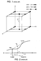
- FIG. 1 illustrates an exemplary sequence of three steps of tri-linear interpolation.
- the interpolation can proceed in pairs along one of the dimensions first, requiring four 1-D linear interpolations, as illustrated by Step 1 in FIG. 1.
- the resulting four values are then used in pairs along one other dimension, requiring two additional 1-D linear interpolations (Step 2).
- the resulting two values are then interpolated along the third dimension, requiring one more 1-D interpolation, to yield the final result (Step 3).
- the tri-linear interpolation requires a total of seven 1-D linear interpolators, implemented in a three-step sequence. As long as the multi-dimensional interpolation is co-linear, this result will hold true and the order of which dimension to use first will not affect the final result.
- the generic method for interpolation described above, using lookup tables and 1-D linear interpolation, is, in fact, commonly used in practice since the color space non-linearity is often too complicated and cannot easily be described with a simple model.
- the traditional approach is to restrict the nodes in the lookup table to be measured on a fixed and uniform grid. While the assumption of equal distance between the nodes certainly simplifies the implementation, it is difficult to justify in practice. It would be desirable to allocate more nodes to those areas of the space that are more important visually, or where the degree of non-linearity is higher, that is, areas where the coarse piece-wise linear approximation accuracy would otherwise not be sufficient.
- the one advantage of the fixed-node scheme is that it is fairly easy to calculate the fractional distance to a base node, and the volume of a cube (in the tri-linear method) or a particular tetrahedron (in the tetrahedron method) is constant anywhere in the space.
- the method of the present invention allows the distance between nodes to be arbitrary, subject to the constraint that the integer non-normalized distance between any adjacent nodes is a binary power-of-two number.
- the motivation for this idea is that a division by an integer power-of-two number can be implemented as a simple shift operation.
- the additional constraint is not very restrictive since the binary power-of-two system is a logarithmic scale that is convenient for describing both small and large steps at the same time.
- the method retains full flexibility to choose the node positions to meet the desired reconstruction fidelity.
- the method typically requires a smaller number of nodes, compared to the uniform grid case for comparable accuracy.
- the simple implementation substantially reduces the associated cost (e.g., number silicon gates in ASIC design and computation complexity), relative to the fully arbitrary node position scheme.
- the lookup table used in the conventional method contains the non-linear mapping from the input domain to the output domain.
- the input domain could be, for example, RGB space, or a more device-independent intermediate space such as YCbCr space or CIE-Lab space (by CIE-Lab space, it is meant the 1976 updated version of the color model first introduced by Commission Internationale d'Eclairage in 1931), as is preferred in some applications
- the output domain is the device (marking engine) CMYK space. Since the nonlinear mapping function from device RGB to any of the above color spaces is either generally unknown or too complicated to implement in a straightforward manner, the content of the lookup table is usually determined by experimentation as part of the calibration process.
- Equation (1) The implementation of Equation (1) involve the following three operations:
- the factor ⁇ i / ⁇ is known and can be precalculated in advance as a normalizing factor.
- the equal spacing constraint fails to provide the flexibility to change the distribution of the nodes in the color space to achieve the highest quality, as discussed above.
- fully programmable node spacing provides the maximum flexibility but the implementation is costly and complicated due to the need to calculate arbitrary divisions as discussed above.
- the present invention addresses both the flexibility (which implies higher quality) of the fully programmable node spacing method and the simplicity (which implies lower cost) of the fixed linear node spacing method discussed above.
- the node spacing ⁇ i expressed as a power-of-two number
- FIG. 3 is a flowchart of an embodiment 300 of the process of the present invention.
- a database of the known nodes is formed.
- the known nodes are chosen such that the distance between any adjacent known nodes is an integer power-of-two number (block 302).
- the database is searched for a base node node1 such that the input node x is located between node1 and an adjacent node2 (block 304).
- the difference between node2 and node1 is 2 k .
- the function values of node1 and node2 are V(node1) and V(node2), respectively (stored in the database).
- Node1 is called a base node because the interpolation will start from the function value V(node1).
- the difference ⁇ between input node x and nodel is computed (block 306).
- the value ⁇ is logically, shifted to the right by k positions, k being the logarithm in base 2 of the distance between the base node node1 and the second node node2 (block 308).
- the function value V(x) is computed by combining V(node1) with the product obtained by multiplying the shifted ⁇ with the difference between V(node2) and V(node1) (block 310).
- the selection of the base node is generally dependent on the origin of the input color space.
- the base node is usually chosen to be less positive than the input node.
- V(node2) - V(node1) is positive.
- the origin of the input color space is not at 0, but somewhere in the middle range (e.g., CIE-Lab space or YCbCr color space with (a,b) or (c b , c r ) ranging from -128 to +127), (see FIG.
- the base node is usually chosen to be less positive than the input node x if the input node x is greater than the origin, and more positive than the input node x if the input node x is smaller than the origin.
- V(node2) - V(node1) is positive for input node x greater than the origin, and negative for input node x smaller than the origin.
- the k values also called inter-node exponents, may be computed in advance and stored in the database. In some applications, the k values may be computed in real time, when needed.
- the following example shows how the database may be formed for an RGB to CMYK color space conversion application.
- a table of arbitrary RGB nodes and their corresponding preferred CMYK values is generated.
- the preferred CMYK values are the ones that would best reproduce the corresponding RGB values, when applied to a particular marking engine.
- the content of the table can be determined by trial and error experimentation, using high-precision instruments to measure actual color values of certain points on the output of the marking engine.
- an interpolation scheme such as the tetrahedral method (discussed previously) can be used on the content of the table to obtain the CMYK values for a set of selected RBG points. These RGB points are selected such that the spacing between any two adjacent selected RGB points is an integer power-of-two number.
- the database is then formed by using only these selected RGB nodes and their corresponding CMYK values.
- FIG. 4 is a block diagram of an embodiment 400 of the system of the present invention.
- System 400 comprises a database 410, a search module 420, and a compute module 430.
- the compute module 430 includes a combine module 432, a shift module 434, and a multiply module 436.
- the database 410 stores a list of known nodes, corresponding known node function values, and inter-node exponents.
- the known nodes are located such that a distance between any two adjacent known nodes is an integer power-of-two number.
- Each of the known nodes that are not located at boundaries of the list is associated with two inter-node exponents which represent the logarithms in base 2 of respective distances between the corresponding known node with respective adjacent known nodes.
- the search module 420 searches from the database for a base node such that the input node is located between the base node and a second node adjacent to the base node.
- the direction of search is programmable based on the location of the origin.
- the combine module 432 computes the difference ⁇ between the input node and the base node, and the difference ⁇ V between the second node function value and the base node function value.
- the shift module 434 shifts ⁇ to the right by k positions, k being the inter-node exponent associated with the base node with respect to the second node.
- the multiply module 436 multiplies the shifted ⁇ with the difference ⁇ V and outputs a product value.
- the combine module 432 combines the base node function value with the product value to form the function value V(x) of the input node.
- the compute module 430 may communicate with the database, as shown in FIG. 4. This is the case where the search module 420 does not pass to the compute module 430 all data resulting from the search. For example, the search module 420 may pass only the node index of the base node. The compute module would use this node index to look up other data in the database 410. In another embodiment where the search module passes all needed data to the compute module 430, the compute module 430 does not need to access the database 410.
- the database 410 includes a single lookup table that includes the node indices corresponding to the known nodes, the known nodes, the corresponding node function values, and the inter-node exponents.
- the inter-node exponents are not stored in a lookup table, and are computed as needed.
- the database 410 includes a main lookup table and an extra lookup table.
- the main lookup table includes the node indices corresponding to the known nodes, and the corresponding node function values.
- the extra lookup table includes the node indices corresponding to the known nodes, the known nodes, and the inter-node exponents.
- This extra lookup table can be used in addition to the main lookup table associated with each of the dimension of the color space.
- the main lookup table looks like a traditional lookup table, i.e., it includes the node indices corresponding to the known nodes, and corresponding node function values. Note that a traditional lookup table only includes the node indices, not the node values, since the node spacing is a constant in traditional interpolation schemes.
- the search for the base node is performed on the extra lookup table first. The resulting base node index will be used to lookup the base node function value and the adjacent node function value in the main lookup table.
- FIG. 5 illustrates an example of the small extra lookup table that may be used in the new architecture.
- the following exemplary pseudo code illustrates how the interpolated output V 0 may be computed for a given input x.
- the bisection algorithm used in the pseudo code is just one of many possible well-known search algorithms that could be used as a searching engine to find the base node.
- the architecture of the present invention can map any bit-precision input to any bit-precision output. Since the input and output are tabulated in the lookup table, any bit-precision representation can be accommodated in the table. In practice, the choice of bit-precision depends on the number of bits used for representing the signal (colors) and the cost to implement. The new architecture does not place any restrictions on the choice of bit-precision.
- FIG. 5 gives an example of color space conversion in which denser samples are needed near the origin 0 (indicated with an asterisk in the nodeValue column). Note that the node spacing is closer for the nodes near the origin than those far from the origin. In FIG. 5, the node spacing goes from 4 near the origin, to 8 then 16 then 32 for nodes located far from the origin. This type of node distribution has been found to be desirable when working with the RGB input color space (where a square root rule is often used in practice).
- the rows in the "exponent" column of FIG. 5 are not aligned with the rows in the nodeIndex and nodeValue columns, to illustrate that each node, not located at the boundaries of the lookup table, is associated with two inter-node exponents.
- node having index 2 and value 8 is associated with inter-node exponent 2 with respect to adjacent node having index 1 and value 4, and with inter-node exponent 3 with respect to node having index 3 and value 16.
- nodeValue denotes the node itself, not the function value of the node (the function values of the nodes are stored in the main lookup table, not in this extra lookup table).
- FIG. 5 is used for input nodes that are expressed as 8-bit numbers.
- FIG. 6 gives an example of an extra lookup table that takes 10-bit input instead of the 8-bit input as shown in FIG. 5.
- the origin is also at 0.
- CIE L,a,b
- Fax L,a,b
- the a and b channels have origin at 128.
- Fax the a channel has origin at 128 but the b channel has origin at 96.
- the new architecture is very flexible and can easily support the various origin differences and needs of the different input color spaces without having to change the implementation.
- the architecture is implementation invariant and generic. Using different lookup tables will serve the needs of different requirements.
- FIG. 7 and FIG. 8 show examples of extra lookup tables for signals having origins at 128 and 96, respectively.
- the table shown in FIG. 7 is used for both the a and b channels for CIE (L,a,b) space, and for the a channel for Fax (L,a,b) space.
- the table shown in FIG. 8 is used for the b channel for Fax (L,a,b) space.
- the lookup table may be loaded with the table shown in FIG. 7 for the a channel, then reloaded with the table shown in FIG. 8 to accommodate the b channel.
- the new method was tested in a Scanner Color Conversion application in which the scanner RGB input was converted to CIE (L,a,b) color output.
- the standard ITU-8 chart was used as a calibration target.
- a reference implementation having non-linear node spacing with twice the number of nodes (to provide denser interpolation) was used as the benchmark.
- the conversion accuracy was measured in terms of the color difference signal ⁇ E between the output CIE Lab values obtained with each of the two methods (traditional method and present invention) and the output CIE Lab values obtained by the benchmark.
- the average ⁇ E obtained for linear node spacing and for power-of-two node spacing were 2.67 and 1.53, respectively.
- This experiment shows that the new power-of-two architecture provides much more accurate conversion than the fixed linear node spacing architecture, and with a small amount of extra computations.
- This experiment shows that, in the application of scanner color space conversion, the method of the present invention improves the color fidelity by almost factor of 2 over the traditional method.
- the new power-of-two node spacing architecture provides a good tradeoff between the flexibility and complexity.
- the architecture of the present invention retains the flexibility to choose nonlinear node spacing to better meet the image quality requirements, and on the other hand, unlike the fully programmable node architecture, the new architecture is simple and cost effective to implement.
Landscapes
- Engineering & Computer Science (AREA)
- Physics & Mathematics (AREA)
- General Physics & Mathematics (AREA)
- Data Mining & Analysis (AREA)
- Theoretical Computer Science (AREA)
- Pure & Applied Mathematics (AREA)
- Mathematical Analysis (AREA)
- Mathematical Optimization (AREA)
- Computational Mathematics (AREA)
- Mathematical Physics (AREA)
- Algebra (AREA)
- Software Systems (AREA)
- General Engineering & Computer Science (AREA)
- Databases & Information Systems (AREA)
- Image Processing (AREA)
- Color Image Communication Systems (AREA)
- Complex Calculations (AREA)
- Facsimile Image Signal Circuits (AREA)
- Management, Administration, Business Operations System, And Electronic Commerce (AREA)
Applications Claiming Priority (2)
| Application Number | Priority Date | Filing Date | Title |
|---|---|---|---|
| US10/134,236 US6975331B2 (en) | 2002-04-26 | 2002-04-26 | Method and system for efficient interpolation using programmable node spacing |
| US134236 | 2002-04-26 |
Publications (2)
| Publication Number | Publication Date |
|---|---|
| EP1376382A2 true EP1376382A2 (fr) | 2004-01-02 |
| EP1376382A3 EP1376382A3 (fr) | 2004-02-04 |
Family
ID=29249177
Family Applications (1)
| Application Number | Title | Priority Date | Filing Date |
|---|---|---|---|
| EP03252544A Withdrawn EP1376382A3 (fr) | 2002-04-26 | 2003-04-23 | Procédé et système d'interpolation efficace utilisant un distance de noeud programmable |
Country Status (3)
| Country | Link |
|---|---|
| US (1) | US6975331B2 (fr) |
| EP (1) | EP1376382A3 (fr) |
| JP (1) | JP4429626B2 (fr) |
Cited By (4)
| Publication number | Priority date | Publication date | Assignee | Title |
|---|---|---|---|---|
| RU2450342C1 (ru) * | 2011-08-01 | 2012-05-10 | Федеральное государственное бюджетное образовательное учреждение высшего профессионального образования "Южно-Российский государственный университет экономики и сервиса" (ФГБОУ ВПО "ЮРГУЭС") | Устройство для восстановления изображений |
| RU2580456C1 (ru) * | 2014-12-30 | 2016-04-10 | Федеральное государственное бюджетное образовательное учреждение высшего профессионального образования "Донской государственный технический университет" (ФГБОУ ВПО "ДГТУ") | Устройство восстановления искаженных значений пикселей изображений |
| RU2582554C1 (ru) * | 2014-12-30 | 2016-04-27 | Федеральное государственное бюджетное образовательное учреждение высшего профессионального образования "Донской государственный технический университет" (ФГБОУ ВПО "ДГТУ") | Устройство восстановления двумерных сигналов на основе реконструкции искаженных пикселей изображений |
| CN113255264A (zh) * | 2021-06-07 | 2021-08-13 | 上海国微思尔芯技术股份有限公司 | 增量分割处理方法、装置、计算机设备和存储介质 |
Families Citing this family (4)
| Publication number | Priority date | Publication date | Assignee | Title |
|---|---|---|---|---|
| US7233695B2 (en) * | 2002-07-01 | 2007-06-19 | Xerox Corporation | Scan color conversion method |
| US7382489B2 (en) * | 2002-07-01 | 2008-06-03 | Xerox Corporation | Efficient interpolation technique using programmable node spacing |
| JP4468270B2 (ja) * | 2005-08-31 | 2010-05-26 | キヤノン株式会社 | 正規化方法および多次元補間装置およびプログラム |
| CN115082323B (zh) * | 2022-08-19 | 2022-11-04 | 深流微智能科技(深圳)有限公司 | 图像处理方法、装置、电子设备及存储介质 |
Citations (3)
| Publication number | Priority date | Publication date | Assignee | Title |
|---|---|---|---|---|
| US5258938A (en) * | 1990-11-30 | 1993-11-02 | Norio Akamatsu | Interpolating method using bit-shift and addition/subtraction operations |
| EP0923048A2 (fr) * | 1997-12-12 | 1999-06-16 | Hewlett-Packard Company | Appareil pour l'interpolation tetraedrique et tetraedrique-réduite |
| US6335800B1 (en) | 1998-12-11 | 2002-01-01 | Xerox Corporation | Method of multidimensional interpolation for color transformations |
Family Cites Families (5)
| Publication number | Priority date | Publication date | Assignee | Title |
|---|---|---|---|---|
| DE3438781A1 (de) * | 1984-10-23 | 1986-04-24 | Robert Bosch Gmbh, 7000 Stuttgart | Elektronische steuereinrichtung fuer eine kraftstoffeinspritzanlage |
| US5184317A (en) * | 1989-06-14 | 1993-02-02 | Pickett Lester C | Method and apparatus for generating mathematical functions |
| US5818744A (en) * | 1994-02-02 | 1998-10-06 | National Semiconductor Corp. | Circuit and method for determining multiplicative inverses with a look-up table |
| US5904222A (en) * | 1996-11-06 | 1999-05-18 | Ford Motor Company | Variable assist power steering using vehicle speed and steering pressure |
| US7215440B2 (en) * | 2000-12-28 | 2007-05-08 | Xerox Corporation | Fast interpolation of large color lookup tables |
-
2002
- 2002-04-26 US US10/134,236 patent/US6975331B2/en not_active Expired - Fee Related
-
2003
- 2003-04-23 EP EP03252544A patent/EP1376382A3/fr not_active Withdrawn
- 2003-04-28 JP JP2003123617A patent/JP4429626B2/ja not_active Expired - Fee Related
Patent Citations (3)
| Publication number | Priority date | Publication date | Assignee | Title |
|---|---|---|---|---|
| US5258938A (en) * | 1990-11-30 | 1993-11-02 | Norio Akamatsu | Interpolating method using bit-shift and addition/subtraction operations |
| EP0923048A2 (fr) * | 1997-12-12 | 1999-06-16 | Hewlett-Packard Company | Appareil pour l'interpolation tetraedrique et tetraedrique-réduite |
| US6335800B1 (en) | 1998-12-11 | 2002-01-01 | Xerox Corporation | Method of multidimensional interpolation for color transformations |
Cited By (5)
| Publication number | Priority date | Publication date | Assignee | Title |
|---|---|---|---|---|
| RU2450342C1 (ru) * | 2011-08-01 | 2012-05-10 | Федеральное государственное бюджетное образовательное учреждение высшего профессионального образования "Южно-Российский государственный университет экономики и сервиса" (ФГБОУ ВПО "ЮРГУЭС") | Устройство для восстановления изображений |
| RU2580456C1 (ru) * | 2014-12-30 | 2016-04-10 | Федеральное государственное бюджетное образовательное учреждение высшего профессионального образования "Донской государственный технический университет" (ФГБОУ ВПО "ДГТУ") | Устройство восстановления искаженных значений пикселей изображений |
| RU2582554C1 (ru) * | 2014-12-30 | 2016-04-27 | Федеральное государственное бюджетное образовательное учреждение высшего профессионального образования "Донской государственный технический университет" (ФГБОУ ВПО "ДГТУ") | Устройство восстановления двумерных сигналов на основе реконструкции искаженных пикселей изображений |
| CN113255264A (zh) * | 2021-06-07 | 2021-08-13 | 上海国微思尔芯技术股份有限公司 | 增量分割处理方法、装置、计算机设备和存储介质 |
| CN113255264B (zh) * | 2021-06-07 | 2021-10-01 | 上海国微思尔芯技术股份有限公司 | 增量分割处理方法、装置、计算机设备和存储介质 |
Also Published As
| Publication number | Publication date |
|---|---|
| US20030201997A1 (en) | 2003-10-30 |
| US6975331B2 (en) | 2005-12-13 |
| EP1376382A3 (fr) | 2004-02-04 |
| JP4429626B2 (ja) | 2010-03-10 |
| JP2004030608A (ja) | 2004-01-29 |
Similar Documents
| Publication | Publication Date | Title |
|---|---|---|
| KR100278567B1 (ko) | 3 차원 색소를 보다 높은 차원의 색소로 변환시키기 위한 시스템, 방법 및 프로그램 | |
| US6766051B2 (en) | Adaptive tree-base lookup for non-separably divided color tables | |
| EP0637731B1 (fr) | Procédé de reproduction d'une couleur | |
| US7199903B2 (en) | Method and device for determining the color appearance of color overprints | |
| US5323249A (en) | Method for reproducing color images having one color gamut with a device having a different color gamut | |
| US6335800B1 (en) | Method of multidimensional interpolation for color transformations | |
| US6707938B2 (en) | Principal axis look-up for color correction | |
| EP0659322A1 (fr) | Procede et appareil de caracterisation pour dispositif de sortie en couleur | |
| US5748176A (en) | Multi-variable colorimetric data access by iterative interpolation and subdivision | |
| KR100278430B1 (ko) | 외부적으로 정의된 4 차원 색소를 등가의 4차원 색소로 변환시키기 위한 시스템, 방법 및 프로그램 | |
| US7215440B2 (en) | Fast interpolation of large color lookup tables | |
| US6304670B1 (en) | Coloration and display of data matrices | |
| US6975331B2 (en) | Method and system for efficient interpolation using programmable node spacing | |
| US20040049497A1 (en) | Efficient interpolation technique using programmable node spacing | |
| US6771275B1 (en) | Processing system and method using a multi-dimensional look-up table | |
| WO2005065092A2 (fr) | Generation dynamique de tables de consultation en couleurs | |
| US5432892A (en) | Volummetric linear interpolation | |
| US5564006A (en) | Real time transformation between color spaces | |
| US7023585B1 (en) | Multi-dimensional edge interpolation | |
| US6621498B1 (en) | High-speed non-separable color table lookup | |
| US5751926A (en) | Function approximation using a centered cubic packing with tetragonal disphenoid extraction | |
| US6587223B1 (en) | Color signal conversion by means of the fewest converter tables | |
| EP0763929B1 (fr) | Procédé de séparation de couleur | |
| EP0923048B9 (fr) | Appareil pour l'interpolation tetraedrique et tetraedrique-réduite | |
| EP1395042A2 (fr) | Méthode et appareil pour conversion de l'espace de couleur |
Legal Events
| Date | Code | Title | Description |
|---|---|---|---|
| PUAI | Public reference made under article 153(3) epc to a published international application that has entered the european phase |
Free format text: ORIGINAL CODE: 0009012 |
|
| PUAL | Search report despatched |
Free format text: ORIGINAL CODE: 0009013 |
|
| AK | Designated contracting states |
Kind code of ref document: A2 Designated state(s): AT BE BG CH CY CZ DE DK EE ES FI FR GB GR HU IE IT LI LU MC NL PT RO SE SI SK TR |
|
| AX | Request for extension of the european patent |
Extension state: AL LT LV MK |
|
| AK | Designated contracting states |
Kind code of ref document: A3 Designated state(s): AT BE BG CH CY CZ DE DK EE ES FI FR GB GR HU IE IT LI LU MC NL PT RO SE SI SK TR |
|
| AX | Request for extension of the european patent |
Extension state: AL LT LV MK |
|
| 17P | Request for examination filed |
Effective date: 20040804 |
|
| 17Q | First examination report despatched |
Effective date: 20040907 |
|
| AKX | Designation fees paid |
Designated state(s): DE FR GB |
|
| 17Q | First examination report despatched |
Effective date: 20040907 |
|
| STAA | Information on the status of an ep patent application or granted ep patent |
Free format text: STATUS: THE APPLICATION IS DEEMED TO BE WITHDRAWN |
|
| 18D | Application deemed to be withdrawn |
Effective date: 20160519 |