EP1376648A1 - Tube à rayons cathodiques - Google Patents
Tube à rayons cathodiques Download PDFInfo
- Publication number
- EP1376648A1 EP1376648A1 EP03075956A EP03075956A EP1376648A1 EP 1376648 A1 EP1376648 A1 EP 1376648A1 EP 03075956 A EP03075956 A EP 03075956A EP 03075956 A EP03075956 A EP 03075956A EP 1376648 A1 EP1376648 A1 EP 1376648A1
- Authority
- EP
- European Patent Office
- Prior art keywords
- transmittance
- shadow mask
- cathode
- ray tube
- panel
- Prior art date
- Legal status (The legal status is an assumption and is not a legal conclusion. Google has not performed a legal analysis and makes no representation as to the accuracy of the status listed.)
- Withdrawn
Links
Images



Classifications
-
- H—ELECTRICITY
- H01—ELECTRIC ELEMENTS
- H01J—ELECTRIC DISCHARGE TUBES OR DISCHARGE LAMPS
- H01J29/00—Details of cathode-ray tubes or of electron-beam tubes of the types covered by group H01J31/00
- H01J29/02—Electrodes; Screens; Mounting, supporting, spacing or insulating thereof
- H01J29/06—Screens for shielding; Masks interposed in the electron stream
- H01J29/07—Shadow masks for colour television tubes
-
- H—ELECTRICITY
- H01—ELECTRIC ELEMENTS
- H01J—ELECTRIC DISCHARGE TUBES OR DISCHARGE LAMPS
- H01J29/00—Details of cathode-ray tubes or of electron-beam tubes of the types covered by group H01J31/00
- H01J29/02—Electrodes; Screens; Mounting, supporting, spacing or insulating thereof
- H01J29/06—Screens for shielding; Masks interposed in the electron stream
- H01J29/07—Shadow masks for colour television tubes
- H01J29/076—Shadow masks for colour television tubes characterised by the shape or distribution of beam-passing apertures
-
- H—ELECTRICITY
- H01—ELECTRIC ELEMENTS
- H01J—ELECTRIC DISCHARGE TUBES OR DISCHARGE LAMPS
- H01J29/00—Details of cathode-ray tubes or of electron-beam tubes of the types covered by group H01J31/00
- H01J29/86—Vessels; Containers; Vacuum locks
-
- H—ELECTRICITY
- H01—ELECTRIC ELEMENTS
- H01J—ELECTRIC DISCHARGE TUBES OR DISCHARGE LAMPS
- H01J2229/00—Details of cathode ray tubes or electron beam tubes
- H01J2229/86—Vessels and containers
- H01J2229/8613—Faceplates
Definitions
- the present invention relates to a color cathode-ray tube, and more particularly to a cathode-ray tube employing a tint or dark tint glass panel in which an optimal transmittance is achieved by solving a problem of deterioration of a brightness balance of the periphery of the screen and the center of the screen caused by the difference between the transmittances in the center and periphery of the screen.
- Fig. 1 illustrates a configuration of a related flat color cathode-ray tube.
- the related flat color cathode-ray tube forms a vacuum tube by which a front side glass panel 1 is combined with a rear side glass funnel 2 and sealed up, thereby its interior is maintained in a vacuum state.
- a fluorescent screen 4 is formed on the internal surface of the panel 1.
- An electron gun assembly 13 is installed in a neck of the funnel 2 facing the fluorescent screen 4.
- a shadow mask 7 that performs a color selection is installed between the fluorescent screen 4 and the electron gun assembly 13 at a predetermined distance from the fluorescent screen 4.
- the shadow mask 7 is fitted to a mask frame 3 and upheld elastically by a spring 8 in order to be supported by the panel 1 with a stud pin 12.
- the mask frame 3 is coupled to an inner shield 9 made of magnetic materials to reduce the effect of the terrestrial magnetic field in the rear portion of the cathode-ray tube for reducing the movements of electron beams caused by an external magnetic field.
- a Convergence Purity Magnet (CPM) 10 for adjusting red (R), green (G), blue (B) electron beams is installed in the neck of the funnel 2 in order to converge the electron beams 6 into a single point, and a deflection yoke 5 is also placed for deflecting the electron beams.
- CPM Convergence Purity Magnet
- a reinforcement band 11 is installed to reinforce the front side glass according to the internal vacuum state.
- the operation of the above-described flat color cathode-ray tube is illustrated hereinafter.
- the electron beams 6 emitted from the electron gun assembly 13 are deflected in vertical and horizontal directions by the deflection yoke.
- the deflected beams pass through beam through holes of the shadow mask 7 and land on the front side of the fluorescent screen 4, thereby displaying a desired color image.
- the CPM 10 adjusts the convergence and purity of the R, G, B electron beams 6.
- the inner shield 9 blocks the effect of the terrestrial magnetic field from the rear side of the cathode-ray tube.
- Fig. 2 illustrates the structure of the shadow mask.
- the shadow mask 7 is made in a dome shape to maintain a predetermined distance from the internal surface of the panel 1.
- the shadow mask 7 is comprised of an effective surface portion 31 having a plurality of slots which are dot or stripe type electron beam through holes formed in the center, an ineffective surface portion 32 surrounding the effective surface portion 31 without the slots, and a mask skirt 33 cut and curved vertically from the ineffective surface portion 32 in the outermost outskirts.
- the frame 3 is welded onto the mask skirt 33.
- the shadow mask 7 has 0.1 to 0.3mm thickness and comprises the plurality of slots 34, which are passages in which the electron beams 6 pass through, are formed in a predetermined arrangement in the effective surface portion 31.
- the slots 34 are arranged in a plurality of rows whose dot or stripe type holes have a predetermined pitch.
- This flat color cathode-ray tube reproduces an image by deflecting the electron beams 6 that have been emitted from the electron gun assembly 13 mounted on the end of the funnel 2 in up, down, right and left directions with the deflection yoke 5 mounted on the external surface of the funnel 2. Thereafter, the deflected electron beams land on the fluorescent screen 4 formed on the internal surface of the panel 1 after passing through the shadow mask 7 having the plurality of the through holes and functions as a color selector.
- brightness and darkness of the image depend largely on the degree of illumination of the fluorescent screen 4 formed on the internal surface of the panel 1 by the electron beams 6, and the amount of the electron beams 6 passing through the slots 34 that are stripe-type holes formed in the shadow mask 7.
- the electron beams 6 pass the panel 1 having a predetermined thickness to display the image.
- a clear glass whose central transmittance is above 75% has a final central transmittance of about 54% and peripheral transmittance of 47%.
- the clear glass has the final central transmittance of about 54% and peripheral transmittance of about 47%, but the tint glass has about 54% and 35%, respectively.
- the peripheral transmittance is substantially lowered in case of the tint glass when compared with the clear glass causing the central to peripheral brightness balance to deteriorate.
- the external surface is almost flat and the internal surface is a kind of dome shape whose center is the thinnest and becomes thicker toward the periphery. Therefore, reducing the thickness means making the dome shape of the internal surface of the panel 1 flat.
- the shape of the shadow mask 7 whose curvature is similar to the one of the dome shape of the internal surface of the panel 1 should also be flat.
- An object of the invention is to solve at least the above problems and/or disadvantages and to provide at least the advantages described hereinafter.
- the present invention is for a cathode-ray tube and has as an object to solve a foregoing problem that the brightness balance of periphery to center of a screen gets degraded due to the difference between glass transmittances for a cathode-ray tube employing a tint or dark tint glass panel.
- a cathode-ray tube comprising a panel having a substantially flat external surface and an internal surface formed with a fluorescent screen in a predetermined curvature, and a shadow mask placed in a predetermined distance apart from the internal surface of the panel and a plurality of electron beam through holes are formed therein, wherein the cathode-ray tube is characterized by having a central transmittance of the panel as 40-75%, a transmittance ratio of the center to a periphery of the panel as 1.4 ⁇ 2.2, and the ratio of the peripheral transmittance to the central transmittance satisfying the following relationship: 0.85 ⁇ Tmd/Tmc ⁇ 1.00, wherein, Tmd is the peripheral transmittance and Tmc represents the central transmittance.
- a cathode-ray tube according to the present invention has advantages of improving the brightness balance and definition of the screen by raising the brightness of the periphery by improving distribution of the transmittances of the center and periphery to raise the ratio of the central to peripheral transmittances.
- the present invention is for a cathode-ray tube comprising a panel whose external surface is substantially flat and internal surface has a fluorescent screen in a predetermined curvature and a shadow mask which is located at a predetermined distance apart from the internal surface of the panel and a plurality of electron beam through holes are formed in it, characterized in that the central transmittance of the panel is 40 ⁇ 75%, transmittance ratio (Tc/Td) of center (Tc) to periphery (Td) of the panel is 1.4 ⁇ 2.2, and the peripheral transmittance (Tmd) and the central transmittance (Tmc) in the shadow mask has a relationship of 0.85 ⁇ Tmd/Tmc ⁇ 1.00.
- the electron beams emitted from the electron gun assembly pass through the slots formed in the shadow mask to land on the fluorescent screen formed on the internal surface of the panel, and then lights generated at this time pass through the panel of tint glass to be displayed as an image.
- the tint glass panel describe above is a panel that has the central transmittance of 40 ⁇ 75% and the Tc/Td ratio of the central transmittance (Tc) to the peripheral transmittance (Td) is 1.4 ⁇ 2.2, and contrast which indicate clearness of the screen is enhanced.
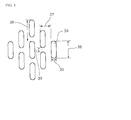
- Fig. 3 shows enlarged view of slots of the shadow mask in order to illustrate the cathode-ray tube according to the present invention.
- the slot 34 of the shadow mask is divided into an input part to which the electron beams emitted from the electron gun assembly are inputted, and an output part from which the electron beams that have passed through the shadow mask are directed to a screen.
- the size of the slot 34 of the input party is generally smaller than the output part.
- the shadow mask slots 34 described in the present invention defines the traveling direction of the electron beams.
- the slots 34 are in a rectangular shape having horizontal width 35 and vertical height 36.
- a bridge(Br) 39 formed between the adjacent slots 34 in a vertical direction and the height(Sl) 36 of the slots 34 are called vertical pitch(Pv) 38.
- the distance between the adjacent slots in a horizontal direction and the width(Sw) 35 of the slots 34 are called horizontal pitch(Ph) 37.
- Things determining the transmittance of the shadow mask are the horizontal pitch(Ph) 37, the slot width(Sw) 35, the vertical pitch(Pv) 38 and the bridge(Br) 39.
- the transmittance may be calculated as the area of the slot/an effective area of the shadow mask.
- the following table 1 illustrates the central transmittance (Tmc) and the peripheral transmittance (Tmd) of the shadow mask.
- Tmc central transmittance
- Tmd peripheral transmittance
- the periphery means, as shown in Fig. 2, diagonal end areas of the effective surface portion of the shadow mask.
- Tmc Tmd Tmd/Tmc Related art 1 20.1% 16.5% 0.82 Related art 2 19.2% 15.9% 0.83 Embodiment 1 19.0% 18.4% 0.97 Embodiment 2 18.9% 18.8% 1.00
- the ratio (Tmd/Tmc) of the peripheral transmittance (Tmd) to the central transmittance (Tmc) is about 0.82 ⁇ 0.83.
- the ratio (Tmd/Tmc) of the peripheral transmittance (Tmd) to the central transmittance (Tmc) of the shadow mask of the flat cathode-ray tube employing the tint glass panel in accordance with the present invention is about 0.97 to 1.00, therefore, the brightness of the periphery is enhanced as the peripheral transmittance is higher than the related art.
- the peripheral brightness of the shadow mask is improved by meeting the following condition: 0.97 ⁇ Tmd/Tmc ⁇ 1.00.
- the peripheral transmittance to the value of the central transmittance (Tmd/Tmc) is 0.965.
- the peripheral transmittance of the tint shadow mask is preferably equal to or larger than the conventional flat cathode-ray tube.
- the peripheral transmittance of the tint shadow mask is preferably 17% or greater.
- Table 2 illustrates the bridge and vertical pitch of the periphery.
- Brd Pvd Brd/Pvd Related art 1 0.149mm 0.595mm 0.25 Related art 2 0.142mm 0.595mm 0.24 Embodiment 1 0.149mm 0.720mm 0.21 Embodiment 2 0.120mm 0.595mm 0.20
- the ratio (Brd/Pvd) of the bridge (Brd) to the vertical pitch (Pvd) is 0.24 ⁇ 0.25 and preferably should be smaller than 0.24 so that the transmittance of the shadow mask can be raised.
- the bridge becomes very small during the mask forming process such that the problem of the bridge being torn may occur.
- the Brd/Pvd ratio of the bridge (Brd) to the vertical pitch (Pvd) of the periphery satisfies the following condition: 0.16 ⁇ Brd/Pvd ⁇ 0.23.
- the bridge (Brd) of the shadow mask should be larger than 0.090mm and smaller than the conventional size of 0.142mm in order to increase the peripheral transmittance of the shadow mask.
- the size of the bridge (Brd) is preferably 0.10mm ⁇ Brd ⁇ 0.14mm.
- the factors that determine the transmittance of the shadow mask other than the vertical pitch (Pvd) and bridge (Brd) are the horizontal pitch (Phd) and slot width (Swd).
- the slot width (Swd) of the shadow mask of the cathode-ray tube employing the tint glass panel is determined by the following equation 2. ⁇ Equation 2 ⁇ ( Ph 3 ) ⁇ ( A B ) ⁇ 0.9 ⁇ Swd ⁇ ( Ph 3 ) ⁇ ( A B )
- A is a predetermined constant indicating a ratio of horizontal pitch of a screen to slot pitch (Ph) of the shadow mask, where the screen is consisted of 3 graphite strips lying close by and R, G, B of the fluorescent materials spread on the internal surface of the panel of Fig. 4.
- the value of A of the periphery is about 1.175
- B is also a predetermined constant representing a ratio Bs/Sw of the size (Bs) of the electron beams passing through the slots, the electron beam through holes of the shadow mask of Fig. 4 to the slot width (Sw) of the shadow mask.
- the B value of the periphery is about 1.593.
- the slot width (Swd) of the periphery of the shadow mask of the present invention has a relation with the horizontal pitch (Phd) of the periphery of the shadow mask like the following equation 3.
- ⁇ Equation 3 Phd ⁇ 0.2213 ⁇ Swd ⁇ Phd ⁇ 0.2459
- Phd is the horizontal pitch and Swd is the slot width.
- the slot width (Swd) of the periphery should be equal to or larger than the horizontal pitch (Phd) multiplied by 0.2213, and equal to or smaller than the one multiplied by 0.2459.
- the size of the electron beams that passed through the slot width (Swd) of 0.220mm becomes approximately 0.350mm (0.220 ⁇ 1.593).
- the size of the electron beams that have passed through the slot width (Swd) of 0.275mm becomes approximately 0.438mm (0.275 ⁇ 1.593) which is larger than 0.407mm, a value of 1/3 of the screen horizontal pitch (P) in size of 1.220mm.
- the color purity can be deteriorated due to an error in positions of beam landing on the R, G, B fluorescent materials.
- the slot width satisfies the equation 3.
- the following table 3 illustrates the ratio Swd/Swc of the slot width (Swd) of the periphery to the slot width (Swc) of the center of the shadow mask.
- Swc Swd Swd/Swc Related art 1 0.189mm 0.213mm 1.13 Related art 2 0.182mm 0.226mm 1.24 Embodiment 1 0.176mm 0.245mm 1.39 Embodiment 2 0.175mm 0.245mm 1.40
- the Swd/Swc value should be larger than 1.3, which is larger than the related values 1.13 ⁇ 1.24. If the Swd/Swc value is larger than 1.6, the Swd should be larger than 0.280mm because the minimum slot width (Swc) needed to form the slots of the shadow mask is 0.175mm. As a result, the size of the electron beams having passed the slots of the shadow mask is too large to cause the deterioration in the color purity.
- the Swd/Swc should satisfy the following condition: 1.3 ⁇ Swd/Swc ⁇ 1.5.
- Swc/T is smaller than 0.7 due to the Swc being smaller than the thickness (T) of the shadow mask, it is difficult to form the slots by means of etching. If the Swc/T is larger than 0.79, the structural strength of the shadow mask becomes weak.
- the Swc/T satisfies the following condition: 0.7 ⁇ Swc/T ⁇ 0.79
- the following table 4 is an embodiment of the tint shadow mask.
- the central transmittance (Tmc) of the shadow mask in accordance with the equation 1 is 19.0% and its peripheral transmittance (Tmd) is 18.4%, thus the peripheral transmittance becomes 18.4% satisfying the formula Tmd ⁇ 17%.
- Tmd/Tmc is 0.965 which also satisfies the formula 0.80 ⁇ Tmd/Tmc.
- the peripheral vertical pitch (Pvd) is 0.720mm and the bridge (Brd) is 0.149. Therefore, Brd/Pvd becomes 0.21, thereby satisfying the condition 0.16 ⁇ Brd/Pvd ⁇ 0.23.
- the peripheral horizontal pitch (Phd) of the shadow mask is 1.057mm and the slot width (Swd) is 0.245mm, so that they are within the rage of 0.2213 ⁇ Ph ⁇ Swd ⁇ 0.2459 ⁇ Ph. That is, the Swd satisfies the formula 0.234mm ⁇ Swd ⁇ 0.260mm.
- the central slot width Swc is 0.176mm and the peripheral slot width Swd is 0.245mm, such that the Swd/Swc becomes 1.4 and satisfies the following conditon: 1.3 ⁇ Swd/Swc ⁇ 1.5.
- the cathode-ray tube according to the present invention has the advantages of improving the brightness balance and definition of the screen by raising the brightness of the periphery through improved distribution of the transmittances rate of the center and periphery to raise the ratio of the central to peripheral transmittances rate.
- the cathode-ray tube according to the present invention has an additional advantage of improving contrast by employing a high definition panel such as tint or dark tint glass.
Landscapes
- Electrodes For Cathode-Ray Tubes (AREA)
- Vessels, Lead-In Wires, Accessory Apparatuses For Cathode-Ray Tubes (AREA)
Applications Claiming Priority (2)
| Application Number | Priority Date | Filing Date | Title |
|---|---|---|---|
| KR10-2002-0035513A KR100443612B1 (ko) | 2002-06-25 | 2002-06-25 | 음극선관용 새도우 마스크 |
| KR2002035513 | 2002-06-25 |
Publications (1)
| Publication Number | Publication Date |
|---|---|
| EP1376648A1 true EP1376648A1 (fr) | 2004-01-02 |
Family
ID=29717719
Family Applications (1)
| Application Number | Title | Priority Date | Filing Date |
|---|---|---|---|
| EP03075956A Withdrawn EP1376648A1 (fr) | 2002-06-25 | 2003-04-02 | Tube à rayons cathodiques |
Country Status (5)
| Country | Link |
|---|---|
| US (1) | US6781301B1 (fr) |
| EP (1) | EP1376648A1 (fr) |
| JP (1) | JP2004031309A (fr) |
| KR (1) | KR100443612B1 (fr) |
| CN (1) | CN1226771C (fr) |
Families Citing this family (1)
| Publication number | Priority date | Publication date | Assignee | Title |
|---|---|---|---|---|
| CN105185994A (zh) * | 2015-08-31 | 2015-12-23 | 中原工学院 | 一种掺杂石墨烯的多孔碳/四氧化三铁纳米纤维锂电池负极材料及其制备方法 |
Citations (4)
| Publication number | Priority date | Publication date | Assignee | Title |
|---|---|---|---|---|
| EP0933797A1 (fr) * | 1998-01-30 | 1999-08-04 | Hitachi, Ltd. | Tube à rayons cathodiques |
| CN1263352A (zh) * | 1999-02-08 | 2000-08-16 | Lg电子株式会社 | 彩色阴极射线管 |
| EP1061548A2 (fr) * | 1999-06-16 | 2000-12-20 | Kabushiki Kaisha Toshiba | Tube de couleur à rayons cathodiques |
| EP1134770A2 (fr) * | 2000-03-13 | 2001-09-19 | Hitachi, Ltd. | Tube couleur à rayons cathodiques |
Family Cites Families (11)
| Publication number | Priority date | Publication date | Assignee | Title |
|---|---|---|---|---|
| JPH08287841A (ja) * | 1995-02-13 | 1996-11-01 | Nec Kansai Ltd | シャドウマスク型カラー陰極線管 |
| US5534746A (en) * | 1995-06-06 | 1996-07-09 | Thomson Consumer Electronics, Inc. | Color picture tube having shadow mask with improved aperture spacing |
| KR100267801B1 (ko) * | 1996-11-05 | 2000-10-16 | 니시무로 타이죠 | 컬러 음극선관 |
| JPH10275568A (ja) * | 1997-03-31 | 1998-10-13 | Nec Kansai Ltd | シャドウマスク型カラー陰極線管 |
| US6160344A (en) * | 1997-04-12 | 2000-12-12 | Samsung Display Devices Co., Ltd. | Cathode-ray tube |
| JPH11288676A (ja) * | 1997-12-10 | 1999-10-19 | Toshiba Corp | カラー受像管 |
| US6639346B2 (en) * | 1997-12-17 | 2003-10-28 | Samsung Display Devices Co., Ltd. | CRT panel and a method for manufacturing the same |
| US6072270A (en) * | 1998-06-22 | 2000-06-06 | Chunghwa Picture Tubes, Inc. | Shadow mask for color CRT |
| KR20000066378A (ko) * | 1999-04-16 | 2000-11-15 | 구자홍 | 칼라음극선관의 섀도우마스크 |
| JP2001351541A (ja) * | 2000-06-01 | 2001-12-21 | Hitachi Ltd | カラー陰極線管 |
| KR20020012867A (ko) * | 2000-08-09 | 2002-02-20 | 김영남 | 샤도우 마스크 |
-
2002
- 2002-06-25 KR KR10-2002-0035513A patent/KR100443612B1/ko not_active Expired - Fee Related
- 2002-11-18 US US10/295,949 patent/US6781301B1/en not_active Expired - Fee Related
- 2002-12-10 CN CNB021564035A patent/CN1226771C/zh not_active Expired - Fee Related
-
2003
- 2003-01-24 JP JP2003016255A patent/JP2004031309A/ja active Pending
- 2003-04-02 EP EP03075956A patent/EP1376648A1/fr not_active Withdrawn
Patent Citations (5)
| Publication number | Priority date | Publication date | Assignee | Title |
|---|---|---|---|---|
| EP0933797A1 (fr) * | 1998-01-30 | 1999-08-04 | Hitachi, Ltd. | Tube à rayons cathodiques |
| CN1263352A (zh) * | 1999-02-08 | 2000-08-16 | Lg电子株式会社 | 彩色阴极射线管 |
| US6411025B1 (en) * | 1999-02-08 | 2002-06-25 | Lg Electronics, Inc. | Color cathode ray tube |
| EP1061548A2 (fr) * | 1999-06-16 | 2000-12-20 | Kabushiki Kaisha Toshiba | Tube de couleur à rayons cathodiques |
| EP1134770A2 (fr) * | 2000-03-13 | 2001-09-19 | Hitachi, Ltd. | Tube couleur à rayons cathodiques |
Also Published As
| Publication number | Publication date |
|---|---|
| CN1226771C (zh) | 2005-11-09 |
| US6781301B1 (en) | 2004-08-24 |
| JP2004031309A (ja) | 2004-01-29 |
| KR20040004722A (ko) | 2004-01-14 |
| CN1466168A (zh) | 2004-01-07 |
| KR100443612B1 (ko) | 2004-08-09 |
Similar Documents
| Publication | Publication Date | Title |
|---|---|---|
| JPH06275206A (ja) | 可変孔ピッチのシャドウマスクを備えたカラー陰極線管 | |
| US5616985A (en) | Shadow-mask color cathode ray tube | |
| US6268690B1 (en) | Color cathode ray tube with face panel and shadow mask having curved surfaces that meet specified relationships | |
| KR100518845B1 (ko) | 음극선관 | |
| US6225735B1 (en) | Shadow mask for color cathode-ray tube and method of manufacturing the same | |
| US20020180331A1 (en) | Color cathode ray tube having improved color purity | |
| US6781301B1 (en) | Cathode-ray tube | |
| EP1170772B1 (fr) | Tube cathodique couleur | |
| US6909227B2 (en) | Color cathode ray tube | |
| US6218772B1 (en) | Color cathode-ray tube with shadow mask mounting system | |
| JP2000011911A (ja) | シャドウマスクを備えたカラー陰極線管 | |
| KR100276354B1 (ko) | 칼라음극선관 | |
| JP3345513B2 (ja) | カラー受像管 | |
| JP2003346677A (ja) | 陰極線管用マスクフレーム | |
| EP0677863B1 (fr) | Tube à rayons cathodiques couleur | |
| US6707241B2 (en) | Color cathode-ray tube | |
| JP2003100231A (ja) | カラー陰極線管 | |
| JPH0574363A (ja) | シヤドウマスク形カラー受像管 | |
| JP2006059574A (ja) | カラー受像管 | |
| JP2002083556A (ja) | カラー陰極線管 | |
| JP2003045355A (ja) | カラー陰極線管 | |
| JP2001035407A (ja) | カラー陰極線管 | |
| JPH10334820A (ja) | カラー受像管 | |
| JP2003217470A (ja) | カラー受像管 | |
| KR20050038269A (ko) | 음극선관 |
Legal Events
| Date | Code | Title | Description |
|---|---|---|---|
| PUAI | Public reference made under article 153(3) epc to a published international application that has entered the european phase |
Free format text: ORIGINAL CODE: 0009012 |
|
| AK | Designated contracting states |
Kind code of ref document: A1 Designated state(s): AT BE BG CH CY CZ DE DK EE ES FI FR GB GR HU IE IT LI LU MC NL PT SE SI SK TR |
|
| AX | Request for extension of the european patent |
Extension state: AL LT LV MK RO |
|
| 17P | Request for examination filed |
Effective date: 20040701 |
|
| 17Q | First examination report despatched |
Effective date: 20040806 |
|
| AKX | Designation fees paid |
Designated state(s): DE FR GB IT |
|
| GRAP | Despatch of communication of intention to grant a patent |
Free format text: ORIGINAL CODE: EPIDOSNIGR1 |
|
| STAA | Information on the status of an ep patent application or granted ep patent |
Free format text: STATUS: THE APPLICATION IS DEEMED TO BE WITHDRAWN |
|
| 18D | Application deemed to be withdrawn |
Effective date: 20061101 |