EP1377017A2 - Terminal portable - Google Patents
Terminal portable Download PDFInfo
- Publication number
- EP1377017A2 EP1377017A2 EP03250832A EP03250832A EP1377017A2 EP 1377017 A2 EP1377017 A2 EP 1377017A2 EP 03250832 A EP03250832 A EP 03250832A EP 03250832 A EP03250832 A EP 03250832A EP 1377017 A2 EP1377017 A2 EP 1377017A2
- Authority
- EP
- European Patent Office
- Prior art keywords
- image
- displayed
- display
- subject
- portable terminal
- Prior art date
- Legal status (The legal status is an assumption and is not a legal conclusion. Google has not performed a legal analysis and makes no representation as to the accuracy of the status listed.)
- Withdrawn
Links
Images


Classifications
-
- H—ELECTRICITY
- H04—ELECTRIC COMMUNICATION TECHNIQUE
- H04N—PICTORIAL COMMUNICATION, e.g. TELEVISION
- H04N1/00—Scanning, transmission or reproduction of documents or the like, e.g. facsimile transmission; Details thereof
- H04N1/00127—Connection or combination of a still picture apparatus with another apparatus, e.g. for storage, processing or transmission of still picture signals or of information associated with a still picture
- H04N1/00281—Connection or combination of a still picture apparatus with another apparatus, e.g. for storage, processing or transmission of still picture signals or of information associated with a still picture with a telecommunication apparatus, e.g. a switched network of teleprinters for the distribution of text-based information, a selective call terminal
- H04N1/00307—Connection or combination of a still picture apparatus with another apparatus, e.g. for storage, processing or transmission of still picture signals or of information associated with a still picture with a telecommunication apparatus, e.g. a switched network of teleprinters for the distribution of text-based information, a selective call terminal with a mobile telephone apparatus
-
- H—ELECTRICITY
- H04—ELECTRIC COMMUNICATION TECHNIQUE
- H04M—TELEPHONIC COMMUNICATION
- H04M1/00—Substation equipment, e.g. for use by subscribers
- H04M1/02—Constructional features of telephone sets
- H04M1/0202—Portable telephone sets, e.g. cordless phones, mobile phones or bar type handsets
- H04M1/0206—Portable telephones comprising a plurality of mechanically joined movable body parts, e.g. hinged housings
- H04M1/0208—Portable telephones comprising a plurality of mechanically joined movable body parts, e.g. hinged housings characterized by the relative motions of the body parts
- H04M1/0214—Foldable telephones, i.e. with body parts pivoting to an open position around an axis parallel to the plane they define in closed position
-
- H—ELECTRICITY
- H04—ELECTRIC COMMUNICATION TECHNIQUE
- H04N—PICTORIAL COMMUNICATION, e.g. TELEVISION
- H04N1/00—Scanning, transmission or reproduction of documents or the like, e.g. facsimile transmission; Details thereof
- H04N1/0035—User-machine interface; Control console
- H04N1/00405—Output means
- H04N1/00408—Display of information to the user, e.g. menus
- H04N1/0044—Display of information to the user, e.g. menus for image preview or review, e.g. to help the user position a sheet
-
- H—ELECTRICITY
- H04—ELECTRIC COMMUNICATION TECHNIQUE
- H04N—PICTORIAL COMMUNICATION, e.g. TELEVISION
- H04N23/00—Cameras or camera modules comprising electronic image sensors; Control thereof
- H04N23/60—Control of cameras or camera modules
- H04N23/63—Control of cameras or camera modules by using electronic viewfinders
-
- H—ELECTRICITY
- H04—ELECTRIC COMMUNICATION TECHNIQUE
- H04M—TELEPHONIC COMMUNICATION
- H04M2250/00—Details of telephonic subscriber devices
- H04M2250/16—Details of telephonic subscriber devices including more than one display unit
-
- H—ELECTRICITY
- H04—ELECTRIC COMMUNICATION TECHNIQUE
- H04N—PICTORIAL COMMUNICATION, e.g. TELEVISION
- H04N2101/00—Still video cameras
-
- H—ELECTRICITY
- H04—ELECTRIC COMMUNICATION TECHNIQUE
- H04N—PICTORIAL COMMUNICATION, e.g. TELEVISION
- H04N2201/00—Indexing scheme relating to scanning, transmission or reproduction of documents or the like, and to details thereof
- H04N2201/0077—Types of the still picture apparatus
- H04N2201/0084—Digital still camera
Definitions
- the present invention relates to a portable terminal provided with a camera comprised of a lens to take a picture of a to-be-taken subject and an image pickup device.
- the portable terminal of the present invention digitally processes an image taken by a camera installed in, for example, a notebook PC, a PDA (Personal Digital Assistant), or a cellular phone and displays the same on a display device of the portable terminal.
- a cellular phone has been provided with a subminiature camera having an image pickup device such as CCD so that the taken image can be attached to an e-mail to be sent.
- a foldable cellular phone it is used in unfolded state to make the lens of a camera, provided on an outer surface of the cellular phone, point toward a partner, and an image is displayed on a display device provided on an inner surface of the cellular phone. The image is adjusted its size and position to be properly taken, and then a shutter key is depressed to take a photo of the partner. Further, the taken photo is sent by e-mail as an attachment.
- the cellular phone When a person who has the cellular phone takes a self-portrait photo, the cellular phone is used in folded state to make a lens of the camera provided on an outer surface of the cellular phone direct to him/herself to display the image of his/her face on a small second display device which is provided on outer surface of the cellular phone and normally displays a date or the like. Further, the taken photo is sent by e-mail as an attachment.
- the photographer can check the facial expression of the partner shown on the display device on inner surface of the cellular phone.
- the partner cannot check how he/she is taken in photo with regard to the size or the expression, and the partner must check the image displayed after taking the photo.
- the present invention is aimed to solve the problems that, when the photographer takes photo of his/her partner using the camera on the cellular phone, the image of the partner is displayed as a reversed image, or information about the photographing status is displayed on the first display which is seen from the partner, concurrent with the image being displayed on the second which can be seen by the photographer so that a partner can check a self-portrait to be taken or the photographing status.
- a portable terminal 1 of the present invention comprises a main LCD 2, shutters 3, 42, a sub LCD 5, a camera 6 and the like.
- the main LCD 2 corresponds to the inner display device of the portable terminal 1 and is a display (a second display) provided on the opposite side, i.e., the different side, on which the lens constituting the camera 6 exists.
- the shutter key 42 or the shutter 3 are to operate a shutter of the camera 6 to take a photo.
- the sub LCD 5 corresponds to the outer display of the portable terminal 1 and is a display (a first display) provided on the same side on which the lens constituting the camera 6 exists.
- the camera 6 is comprised of the lens and the image pickup device and the like, and generates an image of a taken photo of a subject.
- the portable terminal 1 is provided with the sub LCD 5 as the first display on the same side of the lens constituting the camera 6 and the main LCD 2 as the second display on the opposite side of the lens constituting the camera 6, so that a controller 8 makes an image taken by directing the lens to the subject of the photo displayed on the-main LCD 2, and makes the image or the information about the photographing status displayed on the sub LCD 5.
- a stationary image of the subject is displayed on the main LCD 2, and if an image is to be displayed on the sub LCD 5, the stationary image is displayed or if information of the photographing status is to be displayed, a photographing completion information is displayed.
- the image is displayed on the sub LCD 5, the image is scaled down, or is partitioned and one piece of the partitioned image is displayed.
- the sub LCD 5 is provided with a switching unit that switches the image and the information about the photographing status.
- the partner when the partner is taken in photo with the portable terminal 1, the information about and the photographing status and the image reversed like a mirror image are displayed on the first display of the sub LCD 5 which can be seen from the partner, as they are also displayed on the second display of the main LCD 2, so that the partner can check the image to be taken in photo or the photographing status.
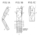
- Fig. 1A to C are external views of a cellular phone.
- Fig. 1A is a side view of an almost unfolded cellular phone
- Fig. 1B is front view of the completely unfolded cellular phone
- Fig. 1C is a front view of the folded cellular phone.
- the portable terminal 1 is provided with the main LCD 2 or the like having the second display on the upper portion of the portable terminal 1 as shown in the inside of the unfolded portable terminal, an input device 4, the controller 8 and the like on the lower portion of the portable terminal 1.
- the main LCD 2 has a display shown as numeral 2, to display a phone number, a transmitting screen.
- the controller 8 performs various controls (image display, transmission control or the like) by a program and a hardware circuit, and is explained below with reference to Fig. 7.
- the shutter 3 is provided on a side of the portable terminal 1, which is folded into two to shoot by operating the camera 6.
- the input device 4 performs various operation instructions, phone number input, e-mail text input by depressing keys, and comprised of a camera key 41, the shutter key 42, a menu key 43, telephone book key 44, a start key 45, a calendar key 46, a clear key 47, a power key 48, a numerical key-pad and the like.
- the camera key is depressed to start up a camera mode.
- the shutter key 42 generates an image taken in a photo by depressing the same.
- the clear key 47 is used to clear various input. In this drawing, the clear key 47 is depressed to clear the taken photo.
- the antenna 7 sends and receives a radio wave.
- the antenna 7 is used to indicate to the photographic object by lighting up a built-in indicator during shooting by depressing the shutter key 42 or the shutter 3.
- Figs. 2A-1, 2A-2, and 2A-3 shows the display side of the sub LCD 5.
- Fig. 2A-1 shows the number of the dots of the screen of the sub LCD 5.
- the sub LCD 5 is derived from 96 dots in the entire vertical direction, 72 dots in a vertical direction to display the image, and 64 dots in the entire horizontal direction.
- Fig. 2A-2 shows the sub LCD 5 showing a message “Shooting" on it.
- the message "Shooting" represents that the camera 6 is taking photo of the to-be-taken subject and the image to be taken is displayed on the main LCD 2.
- Fig. 2A-3 shows the sub LCD 5 showing a message "Displaying" on it.
- the message "Displaying” represents that the still photo of the to-be-taken subject taken by camera 6 is displayed on the main LCD 2.
- Figs. 2B-1, 2B-2 show a screen example of the main LCD 2.
- Fig. 2B-1 shows the number of the dots of the screen of the main LCD 2.
- the main LCD 2 is derived from 176 dots in the entire vertical direction, 140 dots in a vertical direction to display the image, and 132 dots in the entire horizontal direction.
- Fig. 2B-2 shows the main LCD 2 showing a message "Saving image” on it.
- the message "Saving image” represents that the still photo of the to-be-taken subject taken by camera 6 is being saved (stored) as a file (See Figs. 4 and 5).
- Fig. 3 is a top view of a cellular phone of Fi. B.
- the left person is a photographer 51 who has the portable terminal 1 in his/her hand so that the lens of the camera 6 is made directed to the to-be-taken subject 52 to take a photo.
- a through image of the to-be-taken subject 52 (the same image as that the photographer 51 sees the to-be-taken subject 52 directly) is displayed on the main LCD 2.
- the right person, the to-be-taken subject 52, is pointed by the lens of the camera 6 of the portable terminal 1 to be taken in photo.
- a reversed image (reversed left to right like a mirror image) of the to-be-taken subject 52 is displayed on the sub LCD 5.
- the central portable terminal 1 has structures mentioned in Figs. 1A to 1C, Figs. 2A-1 to 2A-3, Fig. 2B-1, and Fig. 2B-2.
- the photographer 51 holds the portable terminal to make the lens of the camera 6 point to the to-be-taken subject 52 and depresses the camera key 41 to switch into the camera mode
- the through image is displayed on the main LCD 2 which can be seen from the photographer 51 while the reversed image is displayed on the sub LCD 5 which can be seen from the to-be-taken subject 52
- the to-be-taken subject 52 can recognize feeling and size of the image to be taken in photo simultaneously, and the image to be taken or taken photo can be shared with the photographer 51 and the to-be-taken subject 52.
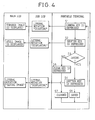
- Fig. 4 is a flow chart to explain an operation of the present invention.
- the main LCD 2 and the sub LCD 5 is the same as that explained in Fig. 1 with the same number.
- the portable terminal 1 detects the depression and carries out the process described below.
- a camera key 41 is depressed in a step S1 that is, the photographer 51 depresses the camera key 41 of the portable terminal 1. According to this depression, a literal notation “Shooting" is displayed on the sub LCD 5 and the through image is displayed on the main LCD 2.
- the photographer 51 has the portable terminal to make the lens of the camera 6 direct to the to-be-taken subject 52 and depresses the camera key 41
- the through image of the to-be-taken subject 52 is displayed on the main LCD 2 which can be seen from the photographer 51 while the literal notation of shooting is displayed on the sub LCD 5 which can be seen from the to-be-taken subject 52, therefore, the to-be-taken subject 52 can recognize that him/herself is been taken in photo.
- a step S2 the photographer depresses (operates) the shutter key 42 provided on the portable terminal 1 or a shutter 3 provided on the side of the portable terminal 1. According to this depression, the massage "Displaying" is displayed on the sub LCD 5 while the still photo is displayed on the main LCD 2.
- the photographer 51 depresses the shutter key 42 or the shutter 3 directing the lens consisting of the camera 6 to the to-be-taken subject 52
- the still image of the to-be-taken subject 52 is displayed on the main LCD 2 which can be seen from the photographer 51 the literal notation that the taken still photo is displayed on the sub LCD 5 which can be seen from the to-be-taken subject 52, thus the to-be-taken subject 52 can recognize that the still image of him/herself is displayed.
- a step S3 the photographer 51 sees the taken still photo displayed on the main LCD 2 and determines whether or not the taken photo is to be saved. If Yes, the flow goes to a step S4. If No, that is, the photographer has decided not to save the photo, the flow goes on to a step S6.
- a step S4 as the photographer decided to save the photo, the shutter key 42 or the shutter 3 is depressed to instruct saving.
- the literal notation "Displaying” is displayed on the sub LCD 5 and the literal notation "Saving Picture” is displayed on the main LCD 2.
- a step S5 the picture is saved in the memory.
- a step S7 in response to the instruction of clearing in the step S6, the still picture in a working memory is cleared.
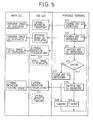
- Fig. 5 is a flow chart to explain another operation of the cellular phone.
- an image of the to-be-taken subject 52 is reversed in the right and left directions like an mirror image on the sub LCD 5 and, to the contrary, the literal notation is displayed on the sub LCD 5 in the flow chart of Fig. 4.
- a camera key 41 is depressed in a step S21, that is, the photographer 51 depresses the camera key 41 of the portable terminal.
- the literal notation "Shooting" is displayed on the sub LCD 5 while the through image is displayed on the main LCD 2.
- the photographer 51 has the portable terminal to make the lens of the camera 6 direct to the to-be-taken subject 52 and depresses the camera key 41, the through image is displayed on the main LCD 2, which can be seen from the photographer 51, while the image reversed in right and left directions is displayed on the sub LCD 5, which can be seen from the to-be-taken subject 52. Therefore, the photographer 51 can see the photographed picture of the to-be-taken subject 52 on the main LCD 2 simultaneously with the to-be-taken subject 52 seeing the image reversed in right and left directions, like a mirror image, displayed on the sub LCD 5.
- a camera key 41 is depressed.
- the image reversed in the right and left directions is displayed on the sub LCD 5 while the through image is displayed on the main LCD 2.
- the camera key 41 is depressed while directing the lens of the camera 6 to the to-be-taken subject 52, the through image is displayed on the main LCD 2 which can be seen from the photographer 51 while the image reversed in right and left directions is displayed on the sub LCD 5 which can be seen from the to-be-taken subject 52. Therefore, the photographer 51 can see the photographed picture of the to-be-taken subject 52 and the to-be-taken subject 52 can see the image reversed in right and left directions.
- a step S23 the photographer 51 depresses (operates) the shutter key 42 of the portable terminal 1 or the shutter 3 provided on the side surface of the portable terminal 1.
- the literal notation "Displaying" or the still photo is displayed on the sub LCD 5 and the still photo is displayed on the main LCD 2.
- a step S24 the photographer 51 sees the photographed still image displayed on the main LCD 2 and determines whether or not the image is to be saved. If Yes, the flow goes to a step S25. If No, that is, the photographer decided not to save the photo, the flow goes on to a step S27.
- a step S25 as the photographer decided to save the photo, the shutter key 42 or the shutter 3 is depressed to instruct saving.
- the literal notation "Displaying” is displayed on the sub LCD 5 and the literal notation "Saving Picture” is displayed on the main LCD 2.
- step S26 the still picture is saved in the memory.
- a step S28 in response to the instruction of clearing in the step S27, the still picture in a working memory is cleared.
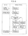
- Fig. 6 is a flow chart explaining further operation of the cellular phone.
- the image displayed on the main LCD 2 is scaled down to be displayed on the sub LCD 5, or partitioned to be displayed one piece of the partitioned image on the sub LCD 5.
- the display on the main LCD 2 is the same as that shown in the flow chart of Fig. 5 and is omitted.
- Fig. 6 the camera key 41 is depressed in a step S41. In response to this depression, the literal notation "Shooting" is displayed on the sub LCD 5.
- a step S42 the camera key 41 is depressed. In response to this depression, the through image is displayed on the sub LCD 51.
- a step S43 it is determined whether the image is to be scaled down. If Yes, the image is scaled down and is displayed on the sub LCD 5, and the flow goes on to a step S46. If No, the calendar key is depressed in a step S47, the partitioned image is displayed on the sub LCD in a step S48, and the flow goes on to a step S49.
- a step S46 the shutter key or the shutter 3 is depressed. in response to this depression, the scaled-down image or a part of the partitioned image is displayed on the sub LCD 5.
- the same image as displayed in the main LCD 2 can be arbitrarily switched to be scaled down or to be partitioned and extract a part thereof to be displayed as necessary on the sub LCD 5 which can be seen from the to-be-taken subject 52.
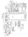
- Fig. 7 is a is a systematic structural viewof a cellular phone of the present invention.
- a main LCD 28 and a sub LCD 30 correspond to the main LCD 2 and the sub LCD 5 respectively.
- a system LSI 11 shows a part of LSI circuit portion comprised of numerals 12 to 21 below.
- An audio interface part 12 amplifies a signal from a microphone 22, sends a speech signal to a receiver 23 and output a sound.
- a voice codec portion 13 encodes speech for easy transmission and decodes encoded speech data to a voice signal.
- a TDMA portion 14 converts the speech data, the image data and character data to a predetermined format and decodes the data from the predetermined format.
- the modulator 15 modulates a signal from the TDMA portion 14 and transmits it to a sending portion 16.
- a demodulator 20 demodulates a signal received by a receiving portion 18.
- a CPU 21 performs various process according to a program stored in a ROM which is not shown and control over entirely.
- the sending portion 16 generates a signal for transmission from a signal from the modulator 15 based on a standard frequency signal from a reference oscillator 19, and sends it to the antenna 7 via a SW 17 as a radio wave.
- the receiving portion 18 receives and amplifies a weak signal received by the antenna 7 via the SW 17, and extracts (receives) it based on a signal from the reference oscillator 19.
- the reference oscillator 19 oscillates at a standard frequency signal and is, for example, a crystal oscillator.
- a power supply/power supply controller 35 supplies a power source to various parts based on a power source from a battery 36, and perform various controls such as charge of the battery 36 when the power is supplied from an AC adopter which is not shown in the drawing.
- the microphone 22 converts the voiced speech to an electric signal.
- a receiver 23 converts electric signal to the voiced speech.
- a memory 25 is stored various data (the image data, the still image data, a phone number, and the like) in itself.
- a main LCD controller 26 controls display of the image and characters on the main LCD 28.
- a main LCD driver portion 27 drives to display the image and characters on the main LCD 28.
- the main LCD 28 displays the image and characters and corresponds to the main LCD 2 in Fig. 1 as mentioned.
- a sub LCD controller/driver portion 29 controls display of the image and characters on the sub LCD 30.
- the sub LCD 30 displays the image and characters and corresponds to the sub LCD 5 in Fig. 1 as mentioned.
- a camera signal processing part 31 takes the image by controlling a camera sensor.
- a camera part 32 is comprised of the camera sensor (CCD, for example), the lens which is not shown, an auto focusing function, and an auto-iris function, and generates an image by taking a picture of the to-be-taken subject 52.
- the camera sensor CCD, for example
- the lens which is not shown
- an auto focusing function for example
- an auto-iris function for example
- a key board 33 is comprised of operation keys such as the shutter key and the camera key, and a numeric keyboard to input a character and a number, and corresponds to the input device in Fig. 1 as above mentioned.
- Side keys 34 are provided on the side surface of the portable device 1 and are the shutter key 3 or the like.
- the camera 5 can be started up, can take a photo, and can save the image by using the camera key 41, the shutter key, and the calendar key 46 which comprise the input device 4 while the portable terminal 1 is unfolded, however, this is an example; the other keys comprising the input device 4 can be used, or, the other keys which do not comprise the input device 4, like any operation keys provided on the side surface of the portable terminal 1 such as the shutter 3, a switch or a slide switch can be provided and used.
- the to-be-taken subject can check the image to be taken or the information about the photographing status, and the photographer and the to-be-taken subject can view the image together so that they can easily adjust the feeling and the size properly.
Landscapes
- Engineering & Computer Science (AREA)
- Signal Processing (AREA)
- Multimedia (AREA)
- Human Computer Interaction (AREA)
- Studio Devices (AREA)
- Telephone Set Structure (AREA)
- Telephone Function (AREA)
- Indication In Cameras, And Counting Of Exposures (AREA)
- Mobile Radio Communication Systems (AREA)
Applications Claiming Priority (2)
| Application Number | Priority Date | Filing Date | Title |
|---|---|---|---|
| JP2002170784A JP4004865B2 (ja) | 2002-06-12 | 2002-06-12 | 携帯端末 |
| JP2002170784 | 2002-06-12 |
Publications (2)
| Publication Number | Publication Date |
|---|---|
| EP1377017A2 true EP1377017A2 (fr) | 2004-01-02 |
| EP1377017A3 EP1377017A3 (fr) | 2006-01-11 |
Family
ID=29717432
Family Applications (1)
| Application Number | Title | Priority Date | Filing Date |
|---|---|---|---|
| EP03250832A Withdrawn EP1377017A3 (fr) | 2002-06-12 | 2003-02-11 | Terminal portable |
Country Status (5)
| Country | Link |
|---|---|
| US (1) | US7821562B2 (fr) |
| EP (1) | EP1377017A3 (fr) |
| JP (1) | JP4004865B2 (fr) |
| KR (1) | KR100832936B1 (fr) |
| CN (1) | CN1268152C (fr) |
Cited By (1)
| Publication number | Priority date | Publication date | Assignee | Title |
|---|---|---|---|---|
| WO2006055104A1 (fr) * | 2004-11-18 | 2006-05-26 | Motorola, Inc. | Dispositif de formation d'image interactif, et procede pour faire fonctionner ce dispositif |
Families Citing this family (16)
| Publication number | Priority date | Publication date | Assignee | Title |
|---|---|---|---|---|
| JP3910112B2 (ja) | 2002-06-21 | 2007-04-25 | シャープ株式会社 | カメラ付携帯電話機 |
| US7340271B2 (en) * | 2003-06-24 | 2008-03-04 | Motorola Inc | Dual input mobile communication device |
| JP2005215643A (ja) * | 2004-02-02 | 2005-08-11 | Toshiba Matsushita Display Technology Co Ltd | 液晶表示装置 |
| KR100557184B1 (ko) * | 2004-06-21 | 2006-03-03 | 삼성전자주식회사 | 카메라와 두개의 표시부를 구비한 휴대용 단말기에서영상을 표시하는 방법 |
| JP2008176661A (ja) * | 2007-01-19 | 2008-07-31 | Fujitsu Ltd | 情報処理装置、制御方法、制御プログラム及び表示装置 |
| JP4592810B2 (ja) * | 2009-07-07 | 2010-12-08 | 株式会社東芝 | 電子機器 |
| JP2010136446A (ja) * | 2010-02-26 | 2010-06-17 | Olympus Imaging Corp | 携帯型撮像機器 |
| WO2012031063A1 (fr) * | 2010-09-03 | 2012-03-08 | The Procter & Gamble Company | Articles de fabrication contenant du polymère et procédé de réalisation de ceux-ci |
| JP2012216951A (ja) * | 2011-03-31 | 2012-11-08 | Toshiba Corp | 電子機器およびインジケータの制御方法 |
| KR101781355B1 (ko) * | 2013-10-07 | 2017-09-25 | 삼성전자주식회사 | 렌즈 분리형 카메라의 동작 방법 및 장치 |
| KR102810509B1 (ko) | 2013-11-28 | 2025-05-22 | 가부시키가이샤 한도오따이 에네루기 켄큐쇼 | 전자 기기 및 그 구동 방법 |
| CN106412158A (zh) * | 2016-09-28 | 2017-02-15 | 努比亚技术有限公司 | 人物拍摄装置和方法 |
| CN107257439B (zh) * | 2017-07-26 | 2019-05-17 | 维沃移动通信有限公司 | 一种拍摄方法及移动终端 |
| CN108008889A (zh) * | 2017-11-30 | 2018-05-08 | 努比亚技术有限公司 | 柔性屏的拍照方法、移动终端及计算机可读存储介质 |
| CN110312988A (zh) * | 2018-06-08 | 2019-10-08 | 深圳市大疆创新科技有限公司 | 屏幕控制的方法和装置 |
| CN116368515A (zh) | 2020-10-21 | 2023-06-30 | 麦克赛尔株式会社 | 便携终端装置 |
Citations (1)
| Publication number | Priority date | Publication date | Assignee | Title |
|---|---|---|---|---|
| EP1111919A2 (fr) * | 1999-12-24 | 2001-06-27 | Nec Corporation | Terminal d'informations portable équipé d'une camera |
Family Cites Families (15)
| Publication number | Priority date | Publication date | Assignee | Title |
|---|---|---|---|---|
| JP3050474B2 (ja) * | 1993-12-01 | 2000-06-12 | シャープ株式会社 | モニタ画面一体型ビデオカメラ |
| KR20010000974A (ko) | 1998-11-02 | 2001-01-05 | 윤종용 | 폴더형 휴대폰에서 양면 액정표시장치 |
| US20020175990A1 (en) * | 1999-03-31 | 2002-11-28 | Jacquelyn Annette Martino | Mirror based interface for computer vision applications |
| FI109742B (fi) | 1999-10-26 | 2002-09-30 | Nokia Corp | Matkaviestin |
| JP2001177742A (ja) * | 1999-12-20 | 2001-06-29 | Minolta Co Ltd | 電子カメラ |
| JP3546997B2 (ja) | 1999-12-24 | 2004-07-28 | 日本電気株式会社 | カメラ付き携帯情報端末装置 |
| CN1302152A (zh) | 1999-12-24 | 2001-07-04 | 日本电气株式会社 | 带有照相机的便携式信息终端 |
| WO2001053919A2 (fr) | 2000-01-24 | 2001-07-26 | Spotware Technologies, Inc. | Assistant numerique modulaire repliable transformable |
| JP2001257911A (ja) | 2000-03-10 | 2001-09-21 | Fuji Photo Film Co Ltd | カメラ |
| JP2001320454A (ja) | 2000-05-11 | 2001-11-16 | Fuji Photo Film Co Ltd | カメラ付き携帯電話機 |
| JP4507392B2 (ja) | 2000-11-15 | 2010-07-21 | 株式会社ニコン | 電子カメラ |
| KR100845828B1 (ko) | 2000-12-29 | 2008-07-14 | 엘지전자 주식회사 | 3단 이중 엘시디 폴더형 휴대용 단말기 및 그 제어방법 |
| US7173665B2 (en) * | 2001-03-30 | 2007-02-06 | Sanyo Electric Co., Ltd. | Folding mobile communication terminal |
| JP2002094629A (ja) | 2001-06-26 | 2002-03-29 | Hitachi Ltd | 情報通信端末装置 |
| JP2003198676A (ja) | 2001-12-28 | 2003-07-11 | Kenwood Corp | 携帯端末装置 |
-
2002
- 2002-06-12 JP JP2002170784A patent/JP4004865B2/ja not_active Expired - Fee Related
-
2003
- 2003-02-07 US US10/359,654 patent/US7821562B2/en not_active Expired - Fee Related
- 2003-02-11 EP EP03250832A patent/EP1377017A3/fr not_active Withdrawn
- 2003-03-04 KR KR1020030013332A patent/KR100832936B1/ko not_active Expired - Fee Related
- 2003-03-05 CN CNB031068545A patent/CN1268152C/zh not_active Expired - Fee Related
Patent Citations (1)
| Publication number | Priority date | Publication date | Assignee | Title |
|---|---|---|---|---|
| EP1111919A2 (fr) * | 1999-12-24 | 2001-06-27 | Nec Corporation | Terminal d'informations portable équipé d'une camera |
Cited By (1)
| Publication number | Priority date | Publication date | Assignee | Title |
|---|---|---|---|---|
| WO2006055104A1 (fr) * | 2004-11-18 | 2006-05-26 | Motorola, Inc. | Dispositif de formation d'image interactif, et procede pour faire fonctionner ce dispositif |
Also Published As
| Publication number | Publication date |
|---|---|
| US20040008266A1 (en) | 2004-01-15 |
| CN1268152C (zh) | 2006-08-02 |
| KR20030095967A (ko) | 2003-12-24 |
| JP4004865B2 (ja) | 2007-11-07 |
| US7821562B2 (en) | 2010-10-26 |
| KR100832936B1 (ko) | 2008-05-27 |
| CN1468016A (zh) | 2004-01-14 |
| EP1377017A3 (fr) | 2006-01-11 |
| JP2004015770A (ja) | 2004-01-15 |
Similar Documents
| Publication | Publication Date | Title |
|---|---|---|
| US7821562B2 (en) | Portable terminal equipped with camera and adapted for self-imaging | |
| US7616261B2 (en) | Folding communication terminal apparatus | |
| JP4053444B2 (ja) | 携帯可能な多機能電子機器 | |
| JP2002290793A (ja) | 撮像装置付携帯電話器 | |
| JP4371016B2 (ja) | 電子機器 | |
| KR100870274B1 (ko) | 휴대 단말 장치, 휴대 단말 장치의 제어 장치, 제어 방법및 제어 프로그램을 기록한 기록매체 | |
| JP2004274777A (ja) | 携帯可能な多機能電子機器 | |
| CN100592750C (zh) | 折叠式通信终端装置 | |
| KR100624883B1 (ko) | 휴대 전화 장치 | |
| JP2008113185A (ja) | 携帯情報端末 | |
| JP2007005915A (ja) | 携帯端末装置 | |
| EP1487195B1 (fr) | DISPOSITIF D'AFFICHAGE D'IMAGES photographiees, PROCEDE D'AFFICHAGE D'IMAGES photographiees et programme d'affichage d'images photographiees | |
| JP4368887B2 (ja) | 携帯端末 | |
| JP4005119B2 (ja) | 携帯端末 | |
| JP2002237880A (ja) | 携帯電話機 | |
| JP4708802B2 (ja) | 携帯端末装置およびプログラム | |
| JP2006060535A (ja) | 携帯電話装置 | |
| JP2001186383A (ja) | カメラ付き携帯情報端末装置 | |
| JP2005311854A (ja) | 撮影制御方法及び携帯端末装置 | |
| KR20060067249A (ko) | 카메라를 이용한 알람 해제기능을 가지는 무선통신 단말기및 그 방법 | |
| JP2005102025A (ja) | 携帯電話機 | |
| JP2005204210A (ja) | カメラ付き携帯型情報端末 | |
| JP2005333384A (ja) | 携帯型電子機器 | |
| JP2004147198A (ja) | 携帯機器 | |
| KR20080021825A (ko) | 절첩식 통신 단말 장치 |
Legal Events
| Date | Code | Title | Description |
|---|---|---|---|
| PUAI | Public reference made under article 153(3) epc to a published international application that has entered the european phase |
Free format text: ORIGINAL CODE: 0009012 |
|
| AK | Designated contracting states |
Kind code of ref document: A2 Designated state(s): AT BE BG CH CY CZ DE DK EE ES FI FR GB GR HU IE IT LI LU MC NL PT SE SI SK TR |
|
| AX | Request for extension of the european patent |
Extension state: AL LT LV MK RO |
|
| PUAL | Search report despatched |
Free format text: ORIGINAL CODE: 0009013 |
|
| AK | Designated contracting states |
Kind code of ref document: A3 Designated state(s): AT BE BG CH CY CZ DE DK EE ES FI FR GB GR HU IE IT LI LU MC NL PT SE SI SK TR |
|
| AX | Request for extension of the european patent |
Extension state: AL LT LV MK RO |
|
| 17P | Request for examination filed |
Effective date: 20060426 |
|
| AKX | Designation fees paid |
Designated state(s): DE FR GB |
|
| 17Q | First examination report despatched |
Effective date: 20060829 |
|
| GRAP | Despatch of communication of intention to grant a patent |
Free format text: ORIGINAL CODE: EPIDOSNIGR1 |
|
| STAA | Information on the status of an ep patent application or granted ep patent |
Free format text: STATUS: GRANT OF PATENT IS INTENDED |
|
| INTG | Intention to grant announced |
Effective date: 20171204 |
|
| RIN1 | Information on inventor provided before grant (corrected) |
Inventor name: KITADA, YASUYUKI Inventor name: AOYAMA, SUSUMU Inventor name: WATANABE, YOSHIKAZU Inventor name: ISHIDA, MAKOTO |
|
| STAA | Information on the status of an ep patent application or granted ep patent |
Free format text: STATUS: THE APPLICATION IS DEEMED TO BE WITHDRAWN |
|
| 18D | Application deemed to be withdrawn |
Effective date: 20180417 |
|
| RIC1 | Information provided on ipc code assigned before grant |
Ipc: H04N 1/00 20060101AFI20030930BHEP |