EP1377137A2 - Circuit et procédé de géneration de tension pour un tube à rayons X - Google Patents
Circuit et procédé de géneration de tension pour un tube à rayons X Download PDFInfo
- Publication number
- EP1377137A2 EP1377137A2 EP03013256A EP03013256A EP1377137A2 EP 1377137 A2 EP1377137 A2 EP 1377137A2 EP 03013256 A EP03013256 A EP 03013256A EP 03013256 A EP03013256 A EP 03013256A EP 1377137 A2 EP1377137 A2 EP 1377137A2
- Authority
- EP
- European Patent Office
- Prior art keywords
- voltage
- manipulated variable
- value
- control device
- ray tube
- Prior art date
- Legal status (The legal status is an assumption and is not a legal conclusion. Google has not performed a legal analysis and makes no representation as to the accuracy of the status listed.)
- Withdrawn
Links
Images

Classifications
-
- H—ELECTRICITY
- H05—ELECTRIC TECHNIQUES NOT OTHERWISE PROVIDED FOR
- H05G—X-RAY TECHNIQUE
- H05G1/00—X-ray apparatus involving X-ray tubes; Circuits therefor
- H05G1/08—Electrical details
- H05G1/26—Measuring, controlling or protecting
- H05G1/30—Controlling
- H05G1/32—Supply voltage of the X-ray apparatus or tube
-
- H—ELECTRICITY
- H05—ELECTRIC TECHNIQUES NOT OTHERWISE PROVIDED FOR
- H05G—X-RAY TECHNIQUE
- H05G1/00—X-ray apparatus involving X-ray tubes; Circuits therefor
- H05G1/08—Electrical details
- H05G1/10—Power supply arrangements for feeding the X-ray tube
- H05G1/20—Power supply arrangements for feeding the X-ray tube with high-frequency AC; with pulse trains
Definitions
- the invention relates to a circuit arrangement for generating an X-ray tube voltage with an inverter circuit for generating a high-frequency AC voltage, with a high-voltage generator for converting the high-frequency AC voltage into a high voltage for the X-ray tube and with a voltage regulating device which is based on the deviation of an actual X-ray tube voltage from a target voltage.
- X-ray tube voltage generates a first manipulated variable value for a manipulated variable for the inverter circuit in order to achieve an adaptation of the actual X-ray tube voltage to the desired X-ray tube voltage.
- Such a circuit arrangement is known from DE 29 43 816 C2.
- the invention relates to an x-ray generator with such a circuit arrangement, an x-ray device with such an x-ray generator and a corresponding method for generating an x-ray tube voltage.
- Modern X-ray generators often have circuit arrangements of the type mentioned at the outset for generating an X-ray tube voltage. Since the mains frequency is first rectified and then converted back into a high-frequency AC voltage, which is finally transformed to the desired voltage, such generators are also referred to as high-frequency generators.
- the voltage regulating device serves to regulate the high voltage on the x-ray tube to the diagnostically required value as optimally as possible and to maintain it there with the required accuracy.
- the circuit arrangement additionally has a measuring circuit for measuring an oscillating current of the high-frequency alternating voltage present at an output of the inverter circuit.
- a second manipulated variable value for the specified manipulated variable for the inverter circuit is then generated on the basis of the deviation of a determined current actual oscillating current value from a predetermined oscillating current maximum value.
- the voltage regulating device and the oscillating current regulating device are then followed by a switching device which compares the first manipulated variable value and the second manipulated variable value and only forwards the respectively smaller manipulated variable value as the resulting manipulated variable value to the inverter circuit.
- the method according to the invention using a vibration current control device, to separately determine a second manipulated variable value on the basis of the deviations of an actual vibration current value from a predetermined maximum oscillation current value and to compare it with the first manipulated variable value of the voltage control device and to supply only the respectively smaller manipulated variable value to the inverter circuit, that, in the normal case, the voltage regulating device regulates very quickly, which is only in the limit cases when a critical range with regard to the oscillating current is reached, is replaced by the oscillating current control device.
- At least one PI controller is used for at least one of the two control devices, particularly preferably for both control devices.
- the integral part of the controller in question has the task of determining the stationary control error. H. to force the control error in the steady state to zero. This reliably avoids a permanent control deviation.
- the control devices preferably consist of successive proportional parts and integral parts. The advantage over a parallel PI controller structure is that the controller parameters regarding gain and reset time can be set separately.
- a PID controller can also be used instead of a PI controller.
- the output of the switching device is connected to an input of the voltage control device and / or the oscillation current control device in order to return the resulting manipulated variable value.
- the voltage regulating device and / or the oscillating current regulating device are designed in such a way that they are carried along with the resulting manipulated variable value when the one generated by the relevant regulating device Manipulated variable value itself is not passed on as the resulting manipulated variable value.
- the respective control device compares the resulting manipulated variable with its own manipulated variable value, which is also traced internally. This variant prevents additional settling processes due to jumps when switching between the two control devices.
- the switching device is preferably designed such that it forwards at least one predetermined minimum manipulated variable value to the inverter circuit as the resulting manipulated variable value.
- a maximum of a predetermined manipulated variable maximum value is preferably also forwarded to the inverter circuit as the resulting manipulated variable value.
- the resulting manipulated variable is actively limited to a range between the minimum value and the maximum value.
- controller parameter a parameter for the set x-ray tube voltage and preferably also for the set x-ray tube current is given to corresponding inputs of the respective control device, as a result of which the parameters of the relevant control devices are set appropriately internally.
- Such a circuit arrangement according to the invention for generating an X-ray tube voltage can in principle be used in any conventional X-ray generator, regardless of how the X-ray generator relates to its other components, such as the various measuring devices or the heating power supply is set up.
- the invention can be used largely independently of the specific design of the inverter circuit and the high-voltage generator.
- FIG. 1a The typical components of an X-ray generator are shown in FIG. 1a, which represent the controlled system with respect to the regulation of the X-ray tube voltage U Rö . These initially include a resonant circuit inverter G si, a high voltage generator G su and an X-ray tube 6.
- the inverter circuit G si has a plurality of power semiconductors 3, which are switched accordingly in such a way that a DC link voltage V z becomes a high-frequency voltage is converted.
- the inverter circuit G si also has a voltage frequency converter 2, which converts a voltage value Y (t) into a drive frequency f a with which the power semiconductors 3 of the inverter G si are driven.
- the input voltage thus forms the manipulated variable Y (t) of the controlled system.
- the G si inverter circuit is a resonant circuit inverter (inverter).
- inverter for example a rectangular inverter or any series or multi-resonance inverter, can also be used.
- the high voltage generator G su consists on the one hand of a transformer 4 with a transmission factor ü and a rectifying and smoothing device 5 connected downstream of the transformer.
- the x-ray tube voltage U Rö present at the output of the rectifying and smoothing device 5 is supplied to the x-ray tube 6.
- FIG. 1b shows a structure diagram for a control loop according to the prior art.
- the inverter circuit G si is shown here as a block and can be described in the control-technical sense by the proportional transmission factor K si and a time constant T si , whereby in particular the proportional transmission factor K si is strongly non-linear due to resonance phenomena in the inverter G si , i.e. from the operating point of the inverter G si depends.
- the high voltage generator G su is also shown as a block. It can be described by the proportional transmission factor K su and the time constant T su , both variables being directly dependent on the X-ray tube voltage U Rö and the X-ray tube current I Rö , ie encompassing a large range of values depending on the operating point .
- i sw (t) is the oscillating current of the inverter G si , which supplies the primary winding of the high-voltage transformer 4 of the high-voltage generator G su . To damage the power semiconductor 3 in of the inverter circuit G si , the oscillating current i sw (t) must not exceed a maximum value.
- the actual voltage V u (t) present there at a specific time t is compared with a desired value W U (t) which corresponds to the desired X-ray tube voltage U Rö , ie the Difference is fed to a voltage control G RU , which is also shown here in the form of a block.
- This voltage control device G RU is conventionally a simple PI controller which, depending on the deviation of the actual value V U (t) from the setpoint W U (t), generates the manipulated variable Y (t), which then responds to the input of the Voltage frequency converter 2 of the inverter circuit G si is given.
- the control speed of the voltage control device G RU must be set so slowly that the oscillating current i sw (t) does not exceed the maximum permissible value even when starting up. This means that rapid regulation with the G RU voltage regulator is not possible, and thus malfunctions can only be regulated slowly.
- the regulator parameters of the voltage regulator G RU must also be adapted accordingly, since the oscillating current i sw (t) is only limited indirectly here.
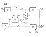
- FIG. 2 clearly shows the change in the structure of the control loop according to the invention.
- the X-ray tube voltage regulating device G RU also forms from the difference between the desired x-ray tube voltage, ie the target voltage W U (t), and the actual x-ray tube voltage, ie the actual x-ray tube voltage V U (t), a manipulated variable Y U (t).
- the oscillating current i sw (t) is measured by means of a smoothing element 7.
- This smoothing element 7 is described in terms of control technology by the additional time constant T MI .
- Both the first manipulated variable value Y U (t), which is formed by the voltage control device G RU , and the second manipulated variable value Y I (t), which is formed by the oscillating current control device G RI , are fed to a switching device 8.
- This switching device 8 selects between the two manipulated variable values Y U (t) and Y I (t) that manipulated variable value Y U (t), Y I (t) that is smaller at the current time t, and routes this manipulated variable value Y U (t ), Y I (t) as the resulting manipulated variable value Y (t) to the inverter circuit G si .
- Both control devices G RI , G RU each contain a PI controller. A permanent control deviation is avoided by the integral part of the PI controller.
- This separation control according to FIG. 2 has the advantage that, in the "normal case", the voltage regulating device G RU is responsible for regulating the x-ray tube voltage. Only in cases in which the current manipulated variable value Y U (t) generated by the voltage regulating device G RU would lead to the oscillating current i sw (t) being a permitted maximum value would exceed, the current manipulated variable value Y I (t) generated by the oscillating current control device G RI is smaller than the manipulated variable value Y U (t) generated by the voltage control device G RU . Therefore, in these cases the voltage regulating device G RU is effectively overridden and only the oscillating current regulating device G RI acts.
- the x-ray tube voltage control itself is not normally slowed down by the measuring time constant T MI of the oscillating current i sw (t) in the structure according to the invention, since the smoothing element 7 is not in the control loop of the x-ray tube voltage.
- the dimensioning of the two control devices G RU , G RI can be made considerably easier if their parameters, ie the controller gains and the reset times, are controlled depending on the working point.
- the two control devices G RI , G RU are each supplied with the values of the set X-ray tube voltage U Rö and the set X-ray tube current I Rö .
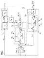
- FIG. 3 shows a more detailed structural diagram of the control loop according to FIG. 2, the control loops here having additional, particularly advantageous features.
- the switching device 8 has further inputs via which the switching device 8 is given a maximum manipulated variable value Y max and a minimum manipulated variable value Y min .
- the switching device 8 is constructed in such a way that at least the manipulated variable minimum value Y min and at most the manipulated variable maximum value Y max are output.
- a manipulated variable range is specified dynamically, within which the manipulated variable Y (t) currently passed on to the inverter circuit G si moves.
- the manipulated variable maximum value Y max and the manipulated variable minimum value Y min are usually set at the factory. In this respect, they can already be specified by appropriate design of the switching device 8 itself.
- FIG. 3 also shows a more precise structure of the voltage regulating device G RU and the oscillating current regulating device G RI .
- These are PI controllers with a proportional component 12, 15 and an integral component 13, 14 connected behind them.
- the proportional components 12, 15 are again determined by the transmission factors K PRI and K PRU and the integral components 13, 14 by the Time constants T NI or T NU .
- the resulting manipulated variable value Y (t) is fed back in this exemplary embodiment by connecting the output 9 of the switching device 8 to additional inputs 10, 11 of the voltage control device G RU or the oscillating current control device G RI .
- the respective manipulated variable value Y U (t), Y I (t) generated by the control device G RU , G RI is also fed back before the integral component 13, 14 and the difference between the feedback, resulting manipulated variable value Y (t) and the respective own manipulated variable value Y U (t), Y I (t) are formed.
- both control devices G RU , G RI each have limit monitors which are coupled such that the integral part 13, 14 of the respectively inactive control device G RU , G RI from the integral part 13, 14 of the active control device - ie the control device G RU , G RI , whose manipulated variable value Y U (t), Y I (t) forms the resulting manipulated variable value Y (t) - is carried along.
- the control devices G RU , G RI would run into the stop, which would result in the integral parts 13, 14 being overloaded. This would in turn lead to a deterioration in the transient response when switching over (wind-up effect).
Landscapes
- Health & Medical Sciences (AREA)
- General Health & Medical Sciences (AREA)
- Toxicology (AREA)
- X-Ray Techniques (AREA)
Applications Claiming Priority (2)
| Application Number | Priority Date | Filing Date | Title |
|---|---|---|---|
| DE10228336 | 2002-06-25 | ||
| DE10228336A DE10228336C1 (de) | 2002-06-25 | 2002-06-25 | Schaltungsanordnung und Verfahren zur Erzeugung einer Röntgenröhrenspannung, sowie Röntgengenerator und Röntgeneinrichtung |
Publications (1)
| Publication Number | Publication Date |
|---|---|
| EP1377137A2 true EP1377137A2 (fr) | 2004-01-02 |
Family
ID=29285719
Family Applications (1)
| Application Number | Title | Priority Date | Filing Date |
|---|---|---|---|
| EP03013256A Withdrawn EP1377137A2 (fr) | 2002-06-25 | 2003-06-12 | Circuit et procédé de géneration de tension pour un tube à rayons X |
Country Status (5)
| Country | Link |
|---|---|
| US (1) | US6768786B2 (fr) |
| EP (1) | EP1377137A2 (fr) |
| JP (1) | JP2004031346A (fr) |
| CN (1) | CN1302692C (fr) |
| DE (1) | DE10228336C1 (fr) |
Families Citing this family (7)
| Publication number | Priority date | Publication date | Assignee | Title |
|---|---|---|---|---|
| DE102009017649B4 (de) * | 2009-04-16 | 2015-04-09 | Siemens Aktiengesellschaft | Emissionsstromregelung für Röntgenröhren |
| DE102009051633B4 (de) * | 2009-11-02 | 2015-10-22 | Siemens Aktiengesellschaft | Spannungsstabilisierung für gittergesteuerte Röntgenröhren |
| DE102012219913B4 (de) | 2012-10-31 | 2015-12-10 | Siemens Aktiengesellschaft | Verfahren zur Regelung der Hochspannung einer Röntgenröhre und zugehöriger Röntgengenerator zur Erzeugung einer Röntgenröhrenspannung |
| CN105792494B (zh) * | 2014-12-22 | 2018-03-23 | 上海西门子医疗器械有限公司 | 电压控制装置、射线管装置以及电压控制方法 |
| CN108051069B (zh) * | 2018-01-09 | 2023-11-21 | 北京工业职业技术学院 | X射线核子秤的校准方法及x射线核子秤 |
| DE102020212085A1 (de) * | 2020-09-25 | 2022-03-31 | Siemens Healthcare Gmbh | System zur Regelung einer Hochspannung für Röntgenanwendungen, ein Röntgenerzeugungssystem und ein Verfahren zur Regelung einer Hochspannung |
| CN116403875B (zh) * | 2023-06-06 | 2023-08-08 | 有方(合肥)医疗科技有限公司 | X射线球管的管电流快速调节方法及装置、ct设备 |
Family Cites Families (8)
| Publication number | Priority date | Publication date | Assignee | Title |
|---|---|---|---|---|
| DE2802513C2 (de) * | 1978-01-20 | 1983-10-06 | Siemens Ag, 1000 Berlin Und 8000 Muenchen | Röntgendiagnostikgenerator mit einem seinen Hochspannungstransformator speisenden Wechselrichter, dem ein LC-Schwingkreis zugeordnet ist |
| DE2943816A1 (de) * | 1979-10-30 | 1981-05-14 | Siemens AG, 1000 Berlin und 8000 München | Roentgendiagnostikgenerator mit einem von einem wechselrichter gespeisten hochspannungstransformator |
| JPS5848398A (ja) * | 1981-09-18 | 1983-03-22 | Toshiba Corp | X線装置 |
| DE3502492A1 (de) * | 1985-01-25 | 1986-07-31 | Heimann Gmbh | Wechselrichter |
| FR2577373B1 (fr) * | 1985-02-12 | 1995-02-17 | Thomson Cgr | Alimentation haute tension continue, notamment pour emetteur de rayons x |
| FR2597285B1 (fr) * | 1986-04-11 | 1988-06-17 | Thomson Cgr | Dispositif d'alimentation en courant d'un filament de tube radiogene |
| FR2672166B1 (fr) * | 1991-01-25 | 1995-04-28 | Gen Electric Cgr | Dispositif pour obtenir une tension continue a faible ondulation residuelle. |
| CN2473856Y (zh) * | 2001-02-21 | 2002-01-23 | 西安天珠电子科技有限公司 | 射线机x射线管控制装置 |
-
2002
- 2002-06-25 DE DE10228336A patent/DE10228336C1/de not_active Expired - Fee Related
-
2003
- 2003-06-12 EP EP03013256A patent/EP1377137A2/fr not_active Withdrawn
- 2003-06-18 JP JP2003172807A patent/JP2004031346A/ja not_active Withdrawn
- 2003-06-20 US US10/601,142 patent/US6768786B2/en not_active Expired - Lifetime
- 2003-06-25 CN CNB031478476A patent/CN1302692C/zh not_active Expired - Fee Related
Also Published As
| Publication number | Publication date |
|---|---|
| US20040017893A1 (en) | 2004-01-29 |
| JP2004031346A (ja) | 2004-01-29 |
| CN1302692C (zh) | 2007-02-28 |
| US6768786B2 (en) | 2004-07-27 |
| DE10228336C1 (de) | 2003-11-27 |
| CN1479564A (zh) | 2004-03-03 |
Similar Documents
| Publication | Publication Date | Title |
|---|---|---|
| DE102014219335B4 (de) | Verfahren und vorrichtung zur unterdrückung von überschwingen für leistungswandler | |
| AT408294B (de) | Sperrwandler | |
| EP1418670A1 (fr) | Contrôle de puissance d'un amplificateur haute fréquence | |
| DE69529408T2 (de) | Stromversorgung | |
| DE10228336C1 (de) | Schaltungsanordnung und Verfahren zur Erzeugung einer Röntgenröhrenspannung, sowie Röntgengenerator und Röntgeneinrichtung | |
| EP1685648B1 (fr) | Amplificateur regule par commande de l'etage de sortie | |
| WO2002007295A1 (fr) | Procede de detection et/ou de limitation de courts-circuits d'un convertisseur a commutation et ledit convertisseur a commutation | |
| DE102024124002A1 (de) | Verfahren und vorrichtung zum regeln eines leistungsfaktorkorrektors | |
| DE112014006190B4 (de) | Schaltnetzteil | |
| WO2016202826A1 (fr) | Source de tension pour des tensions continues modulées | |
| EP0586369B1 (fr) | Procede de circuit pour la transmission de courant continu | |
| WO2015022097A1 (fr) | Commande pilote, basée sur des courbes caractéristiques, des variations de la tension d'entrée et du courant de sortie dans une alimentation à découpage | |
| DE4420600C1 (de) | Verfahren und Anordnung zur Gleichstromübertragung | |
| EP1094592B1 (fr) | Procédé de limitation de tension de sortie pour un convertisseur commandé en tension/fréquence avec circuit intermédiaire et un convertisseur | |
| DE2626831B2 (de) | Nutzbrems-regelanordnung fuer gleichstrommotoren | |
| DE202010012884U1 (de) | Leistungsgeneratoranordnung | |
| DE4106915C2 (fr) | ||
| WO2019174892A1 (fr) | Procédé et dispositif de régulation d'une tension électrique | |
| DE4016018C1 (en) | Process regulating circuitry using two measurers in parallel - has range selection stage cooperating with proportional member and lowest and highest value limiting stages | |
| DE3224301C2 (fr) | ||
| DE10301503A1 (de) | Stromversorgungseinrichtung | |
| EP4686057A1 (fr) | Topologie de convertisseur améliorée pour installations d'électrolyse | |
| DE959569C (de) | Verfahren zum Schutz von Roehrengeneratoren gegen unzulaessige Betriebszustaende beiEntlastung und gegen UEberlastung | |
| WO2024009230A1 (fr) | Procédé et circuit de régulation de courant | |
| DE102021210092A1 (de) | Dynamische Korrektur von verfahrrichtungsabhängigen Offsets |
Legal Events
| Date | Code | Title | Description |
|---|---|---|---|
| PUAI | Public reference made under article 153(3) epc to a published international application that has entered the european phase |
Free format text: ORIGINAL CODE: 0009012 |
|
| AK | Designated contracting states |
Kind code of ref document: A2 Designated state(s): AT BE BG CH CY CZ DE DK EE ES FI FR GB GR HU IE IT LI LU MC NL PT RO SE SI SK TR |
|
| AX | Request for extension of the european patent |
Extension state: AL LT LV MK |
|
| STAA | Information on the status of an ep patent application or granted ep patent |
Free format text: STATUS: THE APPLICATION IS DEEMED TO BE WITHDRAWN |
|
| 18D | Application deemed to be withdrawn |
Effective date: 20060703 |