EP1377404B1 - Verfahren und vorrichtung zur herstellung einer stator- oder rotorkomponente - Google Patents
Verfahren und vorrichtung zur herstellung einer stator- oder rotorkomponente Download PDFInfo
- Publication number
- EP1377404B1 EP1377404B1 EP02715929A EP02715929A EP1377404B1 EP 1377404 B1 EP1377404 B1 EP 1377404B1 EP 02715929 A EP02715929 A EP 02715929A EP 02715929 A EP02715929 A EP 02715929A EP 1377404 B1 EP1377404 B1 EP 1377404B1
- Authority
- EP
- European Patent Office
- Prior art keywords
- edm
- workpiece
- channels
- electro discharge
- component
- Prior art date
- Legal status (The legal status is an assumption and is not a legal conclusion. Google has not performed a legal analysis and makes no representation as to the accuracy of the status listed.)
- Expired - Lifetime
Links
- 238000004519 manufacturing process Methods 0.000 title claims abstract description 26
- 238000000034 method Methods 0.000 title claims abstract description 23
- 238000003754 machining Methods 0.000 claims description 24
- 238000003801 milling Methods 0.000 claims description 18
- 239000000463 material Substances 0.000 claims description 8
- 230000003068 static effect Effects 0.000 description 2
- 230000002950 deficient Effects 0.000 description 1
- 230000005611 electricity Effects 0.000 description 1
- 238000000227 grinding Methods 0.000 description 1
- 239000007788 liquid Substances 0.000 description 1
- 238000012986 modification Methods 0.000 description 1
- 230000004048 modification Effects 0.000 description 1
- 230000000717 retained effect Effects 0.000 description 1
- 229910000601 superalloy Inorganic materials 0.000 description 1
Images


Classifications
-
- B—PERFORMING OPERATIONS; TRANSPORTING
- B23—MACHINE TOOLS; METAL-WORKING NOT OTHERWISE PROVIDED FOR
- B23H—WORKING OF METAL BY THE ACTION OF A HIGH CONCENTRATION OF ELECTRIC CURRENT ON A WORKPIECE USING AN ELECTRODE WHICH TAKES THE PLACE OF A TOOL; SUCH WORKING COMBINED WITH OTHER FORMS OF WORKING OF METAL
- B23H9/00—Machining specially adapted for treating particular metal objects or for obtaining special effects or results on metal objects
- B23H9/10—Working turbine blades or nozzles
Definitions
- the present invention relates to a method for manufacturing a disk-shaped or annular stator component or rotor component with a plurality of blades arranged one after another in a path extending around said component for guiding a gas flow.
- a component can be used in both static applications (stators) and dynamic applications (rotors).
- This component is commonly referred to as a "blisk” (bladed disk) or a "bling” (bladed ring).
- the invention also relates to a device for manufacturing said stator component or rotor component.
- turbopump means a unit which comprises at least a turbine and a pump part driven by the latter.
- the invention is not to be regarded as being limited to this application but can also be used in a gas turbine.
- Other areas of application are also possible, such as in engines for vehicles, aircraft, power plant equipment for vessels and power stations for electricity production.
- the stator component or rotor component is often designed with an annular cover outside the blades in the radial direction and in contact with these. This cover outside the blades is arranged for the purpose of counteracting leakage from a pressure side to a suction side of the blades concerned. Such leakage is associated with efficiency losses.
- each of the blades is manufactured individually.
- the blades are subsequently secured with a mutual spacing in a groove on the periphery of a circular disk so that they project in the radial direction from the latter.
- Each of the blades is often manufactured with a cover part in such a way that an essentially continuous cover is formed after the blades have been mounted on the circular disk.
- each blade is produced separately by electro discharge machining a disk-shaped or annular workpiece intended to form the component.
- electro discharge machining stages and four different electro discharge machining electrodes are required for manufacturing each of said blades.
- EDM electro discharge machining
- half the blade is machined from a first side of the workpiece via a first and a second electro discharge machining operation on the pressure side and, respectively, the suction side of the blade.
- EP 0 426 233 discloses an EDM process for manufacturing an impeller or rotor having a plurality of circumferentially spaced blades.
- a tool is formed by a plate having radial slits cut along a semicircumference around a semicircular recess formed in a side of the plate.
- the disk passes through the plate so that half of the impeller blades are formed on the disk.
- the disk is then rotated 180° and the combined motion of rotation and translation is repeated, wherein the other half of the impeller blades are formed on the disk.
- One object of the invention is to provide a method for manufacturing a disk-shaped or annular stator component or rotor component which is time-efficient and cost-effective.
- the invention also aims to achieve a manufacturing method which creates possibilities for a component with great strength and improved efficiency.
- the manufacturing method is non-sensitive to the material to be machined.
- the stator component or rotor component is manufactured from a single piece, which creates possibilities for great strength, especially in combination with a material which tolerates great temperature transients, such as what is known as a superalloy.
- a plurality of EDM electrodes are in engagement with the workpiece simultaneously.
- the EDM electrodes intended for the electro discharge machining are therefore arranged at a spacing in the circumferential direction of the workpiece which is greater than the intended spacing between the channels. In other words, machining of a plurality of channels takes place simultaneously, after which the EDM means is indexed and a new set of channels can be machined out of the workpiece.
- the workpiece is turned after all the channels have been electro discharge machined from a first side of the same, and the remaining portion of the channels is then electro discharge machined in the same way from its second side. In this way, relatively complex blade shapes can also be produced.
- said channels are electro discharge machined at a spacing from the edge of the workpiece in the radial direction, so that a cover is formed outside the blades in the radial direction and in contact therewith.
- the cover is formed by the material of the workpiece remaining outside the blades in the radial direction. In this way, a continuous cover is formed, which creates possibilities for a component with great efficiency.
- a plurality of EDM electrodes are machined, with a mutual spacing along a curved path, from at least one basic element arranged on a means intended for the EDM, and, in a second operation, the channels are electro discharge machined from the workpiece by means of said EDM electrodes.
- the machining in the first operation preferably comprises milling.
- the method for manufacturing the component therefore comprises two stages, namely firstly manufacturing the tool itself which is to be used for EDM and subsequently electro discharge machining of the workpiece by means of the EDM tool manufactured in this way.
- the attachment of the EDM means has such a shape that it can be used on the one hand in a machine tool for said manufacture of the EDM electrodes and on the other hand in an EDM machine for said manufacture of the channels by EDM.
- the method can be implemented by means of conventional machines for milling and EDM.
- a plurality of said basic elements are arranged on the EDM means in a path extending around said means before machining, and at least one of said EDM electrodes is machined from each of them in the first operation.
- Another object of the invention is to produce a device which creates possibilities for time-efficient and cost-effective manufacture of a disk-shaped or annular stator component or rotor component. This object is achieved by a device according to claim 12. Further advantageous embodiments of the invention emerge from the following claims and the description.
- the method for manufacturing a stator component or rotor component 1 comprises two stages, namely firstly manufacturing the tool itself which is to be used in subsequent EDM and then electro discharge machining a workpiece 2 by means of the EDM tool manufactured in this way.
- the manufacture of the EDM tool is carried out by milling.
- EDM electrode 6 In electro discharge machining, material is removed from the surface of the workpiece 2 under the action of a power density which arises when short electrical discharges take place between an EDM electrode 6 and the workpiece 2, see Figure 2 .
- the workpiece 2 and the EDM tool are submerged in a dielectric liquid, and voltage is applied, material then being burned away from the workpiece.
- the EDM tool forms a cathode
- the workpiece forms an anode.
- the EDM electrode has the shape of a negative replica of the intended shape of the cutout.
- Fig. 1 shows a plurality of basic elements 3 arranged in an at least essentially circular path on a top side of a holder element which comprises a disk 4.
- the basic elements 3 are secured on the disk 4 by screw joints 18.
- Each of the basic elements 3 has three upwardly projecting portions 5 which are intended to form EDM electrodes 6, see Figure 2 .
- the disk 4 is arranged in a milling machine 7 known per se, and each of the projecting portions 5 is intended to be machined using a milling tool 8.
- the upwardly projecting portions 5 are arranged at a sufficiently great spacing from one another for it to be possible to reach with the milling tool 8 for the purpose of giving the projecting portions 5 the desired shape.
- the EDM electrodes 6 are machined from the basic elements 3 by milling, with a mutual spacing along a circular path.
- the holder element comprising the disk 4 and a first machine attachment part 9 located under the disk and connected rigidly thereto form an EDM means intended for an EDM operation following the milling operation.
- the first machine attachment part 9 is designed so as to be capable of being used both in a milling machine and in an EDM machine.
- the first machine attachment part 9 is designed so as to fit together with a second machine attachment part 17 of the milling machine.
- the first and second machine attachment parts 9, 17 are designed with male and female parts for engagement with one another.
- the first machine attachment part 9 has three recesses 16 arranged with even spacing in the circumferential direction of the disk 4.
- the recesses 16 are open in a direction opposite to that side of the disk 4 on which the basic pieces 3 are arranged.
- the second machine attachment part 17 has three projecting portions 19 for fitting into the recesses 16. In this way, highly accurate centering of the disk 4 is brought about.
- the projecting portions 19 have the shape of a truncated cone.
- the EDM means is referred to below using reference number 4.
- Figure 1 illustrates the basic elements 3 before milling has been started.
- the EDM means 4 is arranged at the top in an EDM machine 10.
- the EDM means 4 has been turned through 180° so that the EDM electrodes 6 project downward.
- the EDM means 4 has seven basic elements 3 which each have three EDM electrodes 6. In total, there are 21 EDM electrodes. After a reciprocating movement of the EDM means during EDM, 21 cutouts 11 are therefore formed in a workpiece 2.
- Figure 2 illustrates that the cutouts 11 do not extend through the entire thickness of the disk.
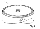
- the cutouts 11 are intended to form channels 12, see Figure 3 . Two adjacent such channels 12 in turn delimit a blade 13.
- the cutouts 11 extend roughly halfway through the disk.
- the EDM machine has a third machine attachment part 20, see Figure 2 .
- the lower part 21 of this is designed for engagement with the recesses 16 and is preferably identical with the second machine attachment part 17 of the milling machine 7 for the purpose of bringing about good centering of the EDM means 4.
- the third machine attachment part 20 therefore has three cone-shaped projecting portions 22 for engagement with the recesses 16.
- a portion (said 21 cutouts 11) of each of a plurality of channels 12 in a first set of channels is therefore machined out of the workpiece 2.
- the EDM means 4 is then rotated through a number of degrees and then, in a second EDM stage, 21 further cutouts are machined.
- the EDM operation continues with further rotation of the EDM means followed by further EDM stages until the spacing between two adjacent cutouts 11 in the circumferential direction of the workpiece 2 is essentially the same around the entire workpiece and corresponds to the desired blade thickness.
- Figure 2 illustrates the workpiece when the EDM operation from a first flat side thereof has been performed.
- the EDM operation continues after the workpiece 2 has been turned, and electro discharge machining is then carried out in the same way from its second flat side.
- the cutouts from the second side of the workpiece are electro discharge machined out of the workpiece 2 so that they are connected to the cutouts 11 from the first side, and in this way said channels 12 are formed.
- the channels 12 will thus extend through the workpiece in the axial direction at a spacing from its edge 14 in the radial direction.
- the blades 13 are defined between the channels 12 in the circumferential direction of the workpiece.
- Each of the EDM electrodes 6 has a shape which corresponds essentially to the shape of the desired channels 12.
- the EDM means 4 is made to perform both a reciprocating movement and a rotary movement in each EDM stage.
- each EDM electrode 6 is guided into the workpiece 2 along a predetermined path.
- the EDM means 6 is made to perform an oscillating movement when the EDM electrodes have reached their final position in order to produce the desired structure on the channel walls.
- the machine attachment 9 of the EDM means 4 is designed so that it is possible to use the EDM means 4 both clamped on, in a static position, in a milling machine for machining the EDM electrodes 6 and for rotation in a EDM machine for the purpose of machining the workpiece 2.
- the invention is not to be regarded as being limited to the illustrative embodiments described above, but a number of further variants and modifications are conceivable within the scope of the following patent claims.
Landscapes
- Physics & Mathematics (AREA)
- Thermal Sciences (AREA)
- Engineering & Computer Science (AREA)
- Mechanical Engineering (AREA)
- Electrical Discharge Machining, Electrochemical Machining, And Combined Machining (AREA)
- Turbine Rotor Nozzle Sealing (AREA)
- Iron Core Of Rotating Electric Machines (AREA)
- Manufacture Of Motors, Generators (AREA)
- Spark Plugs (AREA)
Claims (13)
- Verfahren zur Herstellung einer scheibenförmigen oder ringförmigen Statorkomponente oder Rotorkomponente (1) mit einer Vielzahl von Schaufeln (13), die nacheinander auf einem Weg angeordnet sind, der sich um die Komponente herum zum Führen eines Gasstroms erstreckt, wobei- wenigstens ein Abschnitt (11) eines jeden einer Vielzahl von Kanälen (12) in einem ersten Satz von Kanälen gleichzeitig aus einem zur Bildung der Komponente (1) vorgesehenen scheibenförmigen oder ringförmigen Werkstück (2) durch Elektroerosion herausgearbeitet wird, und- die Kanäle (12) zur Begrenzung der Schaufeln (13) in der Umfangsrichtung des Werksstücks vorgesehen sind,dadurch gekennzeichnet,- dass für die Bearbeitung durch Elektroerosion EDM- (Elektro Discharge Machining-)Elektroden in einem Abstand in der Umfangsrichtung des Werkstücks angeordnet sind, der größer ist als der zwischen den Kanälen vorgesehene Abstand,- dass nach der Elektroerosionsbearbeitung des Abschnitts (11) des ersten Satzes von Kanälen (12) das Werkstück (2) über eine Entfernung in seiner Umfangsrichtung gedreht wird und dann wenigstens ein Abschnitt eines jeden der Vielzahl von Kanälen (12) in einem zweiten Satz von Kanälen durch Elektroerosion herausgearbeitet wird, und- dass der EDM-Vorgang bei einer weiteren Drehung der EDM-Einrichtungen gefolgt von weiteren EDM-Schritten fortgesetzt wird, bis der Abstand zwischen zwei benachbarten Kanalabschnitten (11) in der Umfangsrichtung des Werkstücks (2) um das ganze Werkstück herum im Wesentlichen der gleiche ist und der gewünschten Schaufeldicke entspricht.
- Verfahren nach Anspruch 1, dadurch gekennzeichnet, dass das Werkstück (2), nachdem alle Kanäle von seiner ersten Seite aus elektroerosiv herausgearbeitet wurden, gedreht wird und dass der restliche Teil der Kanäle (12) dann auf die gleiche Weise von der zweiten Seite des Werkstücks aus elektroerosiv herausgearbeitet wird.
- Verfahren nach einem der vorhergehenden Ansprüche, dadurch gekennzeichnet, dass eine Elektrode (6) für eine elektroerosive Bearbeitung im Verlauf ihrer Bahn in dem Werkstück (2) zur gleichzeitigen Ausführung einerseits einer translatorischen Bewegung und andererseits einer Drehbewegung veranlasst wird.
- Verfahren nach einem der vorhergehenden Ansprüche, dadurch gekennzeichnet, dass zwei gegenüberliegende Oberflächen eines jeden der Kanäle (12) in der Umfangsrichtung des Werkstücks (2) gleichzeitig elektroerosiv bearbeitet werden.
- Verfahren nach Anspruch 4, dadurch gekennzeichnet, dass die gegenüberliegenden Oberflächen eines jeden der Kanäle (12) durch die gleiche EDM-Elektrode (6) elektroerosiv bearbeitet werden.
- Verfahren nach einem der vorhergehenden Ansprüche, dadurch gekennzeichnet, dass die Kanäle (12) in einem Abstand von dem Rand (14) des Werkstücks in Radialrichtung so elektroerosiv bearbeitet werden, dass ein Deckel (15) außerhalb der Schaufeln in der Radialrichtung und in Kontakt damit gebildet wird.
- Verfahren nach einem der vorhergehenden Ansprüche, dadurch gekennzeichnet, dass in einem ersten Vorgang eine Vielzahl von EDM-Elektroden (6) bearbeitet wird, die einen gegenseitigen Abstand längs einer gekrümmten Bahn von wenigstens einem Basiselement (3, 5) aus haben, das auf einer Einrichtung (4) für die elektroerosive Bearbeitung angeordnet ist, und dass in einem zweiten Vorgang die Kanäle (12) aus dem Werkstück (2) mit Hilfe der EDM-Elektroden (6) elektroerosiv herausgearbeitet werden.
- Verfahren nach Anspruch 7, dadurch gekennzeichnet, dass die Befestigung (7) der EDM-Einrichtungen (4) eine solche Form hat, dass sie einerseits in einer Werkzeugmaschine zur Herstellung der EDM-Elektroden (6) und andererseits in einer EDM-Maschine für die Herstellung der Kanäle (12) durch Elektroerosionsbearbeitung verwendet werden kann.
- Verfahren nach Anspruch 7 oder 8, dadurch gekennzeichnet, dass eine Vielzahl der Basiselemente (3, 5) an der EDM-Einrichtung (4) auf einer gekrümmten Bahn vor der Bearbeitung angeordnet werden, und dass wenigstens eine der EDM-Elektroden aus jedem von ihnen in dem ersten Vorgang herausgearbeitet wird.
- Verfahren nach einem der Ansprüche 7 bis 9, dadurch gekennzeichnet, dass die Bearbeitung in dem ersten Vorgang das Fräsen ist.
- Vorrichtung zur Herstellung einer scheibenförmigen oder ringförmigen Statorkomponente oder Rotorkomponente (1) mit einer Vielzahl von Schaufeln (13), die nacheinander auf einer Bahn angeordnet sind, die sich um die Komponente herum zum Führen eines Gasstroms erstreckt, wobei die Vorrichtung eine EDM-Einrichtung (4) aufweist, die für den Anschluss an eine Spannung und für das In-Kontakt-Bringen mit einem Werkstück (2) zum Entfernen von Material aus dem Letzteren zur Bildung einer der Schaufeln angepasst ist, dadurch gekennzeichnet,- dass die EDM-Einrichtung (4) eine Vielzahl von EDM-Elektroden (6) für den Kontakt mit dem Werkstück aufweist,- dass die EDM-Elektroden für die elektroerosive Bearbeitung in einem Abstand in der Umfangsrichtung des Werkstücks angeordnet sind, der größer ist als der vorgesehene Abstand zwischen den Kanälen,- dass die EDM-Elektroden in einem gegenseitigen Abstand voneinander auf einer gekrümmten Bahn so angeordnet sind, dass wenigstens ein Abschnitt (11) eines jeden einer Vielzahl von Kanälen (12) in einem ersten Satz von Kanälen gleichzeitig auf dem Werkstück (2) elektroerosiv herausgearbeitet werden kann, das scheibenförmig oder ringförmig zur Bildung der Komponente (1) ist,- wobei die Kanäle (12) zur Begrenzung der Schaufeln (13) in der Umfangsrichtung des Werkstücks vorgesehen sind.
- Vorrichtung nach Anspruch 11, dadurch gekennzeichnet, dass die EDM-Elektroden (6) eine nach der anderen auf einer Bahn angeordnet sind, die wenigstens teilweise kreisförmig ist.
- Vorrichtung nach Anspruch 11 oder 12, dadurch gekennzeichnet, dass die EDM-Einrichtung (4) eine Scheibe und eine Vielzahl von Basiselementen (3) aufweist, die an der Scheibe befestigt sind, und dass jedes der Basiselemente eine Vielzahl der EDM-Elektroden (6) aufweist.
Applications Claiming Priority (3)
| Application Number | Priority Date | Filing Date | Title |
|---|---|---|---|
| SE0100880A SE518806C2 (sv) | 2001-03-14 | 2001-03-14 | Förfarande och anordning för framställning av en stator- eller rotorkomponent |
| SE0100880 | 2001-03-14 | ||
| PCT/SE2002/000086 WO2002072303A1 (en) | 2001-03-14 | 2002-01-18 | A method and a device for manufacturing a stator component or rotor component |
Publications (2)
| Publication Number | Publication Date |
|---|---|
| EP1377404A1 EP1377404A1 (de) | 2004-01-07 |
| EP1377404B1 true EP1377404B1 (de) | 2008-06-25 |
Family
ID=20283352
Family Applications (1)
| Application Number | Title | Priority Date | Filing Date |
|---|---|---|---|
| EP02715929A Expired - Lifetime EP1377404B1 (de) | 2001-03-14 | 2002-01-18 | Verfahren und vorrichtung zur herstellung einer stator- oder rotorkomponente |
Country Status (8)
| Country | Link |
|---|---|
| US (1) | US6797912B2 (de) |
| EP (1) | EP1377404B1 (de) |
| JP (1) | JP4086228B2 (de) |
| AT (1) | ATE399072T1 (de) |
| DE (1) | DE60227246D1 (de) |
| RU (1) | RU2276633C2 (de) |
| SE (1) | SE518806C2 (de) |
| WO (1) | WO2002072303A1 (de) |
Cited By (1)
| Publication number | Priority date | Publication date | Assignee | Title |
|---|---|---|---|---|
| KR20210069342A (ko) | 2019-12-03 | 2021-06-11 | 한국항공우주연구원 | 일체형 복열 터빈 블리스크의 방전가공방법, 이를 이용하는 방전가공장치, 및 이에 의해 제작된 일체형 복열 터빈 블리스크 |
Families Citing this family (19)
| Publication number | Priority date | Publication date | Assignee | Title |
|---|---|---|---|---|
| DE10258920A1 (de) * | 2002-12-17 | 2004-07-01 | Rolls-Royce Deutschland Ltd & Co Kg | Verfahren und Vorrichtung zur Formgebung durch elektrochemisches Abtragen |
| KR100673964B1 (ko) * | 2005-01-28 | 2007-01-24 | 삼성테크윈 주식회사 | 터빈 블레이드의 방전가공 방법 및 이에 적용되는 터빈블레이드의 방전가공 장치 |
| CN100450686C (zh) * | 2006-10-19 | 2009-01-14 | 杨龙兴 | 一种汽轮机叶片的线切割加工工艺方法 |
| PL2143996T3 (pl) * | 2008-02-19 | 2013-12-31 | Balcke Duerr Gmbh | Kolektor dla wysokociśnieniowego urządzenia siłowni parowych |
| DE102008052947A1 (de) * | 2008-10-23 | 2010-04-29 | Siemens Aktiengesellschaft | Verfahren zur Herstellung von Laufschaufeln und einer Radscheibe für eine Turbomaschine sowie Vorrichtung, aufweisend Laufschaufeln und eine Radscheibe für eine Turbomaschine |
| US20110073464A1 (en) * | 2009-09-28 | 2011-03-31 | General Electric Company | Systems and apparatus relating to electrochemical machining |
| GB0917317D0 (en) * | 2009-10-02 | 2009-11-18 | Bladon Jets Ltd | Rotary structures |
| CA2859353A1 (en) | 2011-12-15 | 2013-06-20 | Sumi Dinkar | Moisture curable organopolysiloxane compositions |
| JP6267128B2 (ja) | 2011-12-15 | 2018-01-24 | モーメンティブ・パフォーマンス・マテリアルズ・インク | 湿気硬化性オルガノポリシロキサン組成物 |
| US9527959B2 (en) | 2011-12-29 | 2016-12-27 | Momentive Performance Materials Inc. | Moisture curable organopolysiloxane composition |
| US9162301B2 (en) | 2012-08-06 | 2015-10-20 | General Electric Company | Electrochemical machining tools and methods |
| US8906221B2 (en) | 2012-08-06 | 2014-12-09 | General Electric Company | Electrochemical grinding tool and method |
| TW201434882A (zh) | 2013-03-13 | 2014-09-16 | Momentive Performance Mat Inc | 可濕氣固化之有機聚矽氧烷組成物 |
| WO2014183029A2 (en) | 2013-05-10 | 2014-11-13 | Momentive Performance Materials Inc. | Non-metal catalyzed room temperature moisture curable organopolysiloxane compositions |
| FR3006925B1 (fr) * | 2013-06-17 | 2016-01-15 | Snecma | Procede de realisation d'alveoles d'un disque de turbomachine |
| EP2829344A1 (de) * | 2013-07-22 | 2015-01-28 | Merit Precision Tools Limited | Verfahren zur Herstellung und Verwendung eines Werkstücks, insbesondere einer Elektrode zur Funkenerosion |
| FR3042138B1 (fr) * | 2015-10-07 | 2018-05-25 | Pemtec | Outillage pour l'usinage d'alveoles de disques multi-etages par pecm, ensemble et machine d'usinage electrochimique comportant cet outillage, et procede utilisant cet outillage |
| FR3082129B1 (fr) * | 2018-06-12 | 2021-01-01 | Arianegroup Sas | Procede de fabrication d'une turbine, en particulier pour turbopompe |
| US11273508B2 (en) * | 2018-12-31 | 2022-03-15 | Ge-Hitachi Nuclear Energy Americas Llc | Electrical discharge machining assemblies and methods for using the same |
Family Cites Families (10)
| Publication number | Priority date | Publication date | Assignee | Title |
|---|---|---|---|---|
| SU1291316A1 (ru) * | 1985-01-09 | 1987-02-23 | Предприятие П/Я Р-6930 | Устройство дл электроэрозионной обработки электродом-проволокой |
| EP0327657A1 (de) * | 1988-02-11 | 1989-08-16 | Leistritz Aktiengesellschaft | Verfahren zum Herstellen eines Schaufelrades |
| US4888863A (en) * | 1988-03-21 | 1989-12-26 | Westinghouse Electric Corp. | Method and apparatus for producing turbine blade roots |
| IT1238201B (it) * | 1989-11-03 | 1993-07-09 | Varian Spa | Metodo di fabbricazione mediante elettroerosione di una girante o di un rotore a una o piu' giranti di una turbopompa, particolarmente di una pompa turbomolecolare, e prodotti cosi' ottenuti. |
| US5014421A (en) * | 1989-12-26 | 1991-05-14 | Ingersoll-Rand Company | Contoured blade edge cutting method |
| DE4203656C2 (de) * | 1992-02-08 | 2000-06-21 | Abb Patent Gmbh | Vorrichtung zur Herstellung von Axialnuten an Läuferscheiben eines Turbinenläufers |
| RU2058863C1 (ru) * | 1992-08-13 | 1996-04-27 | Акционерное общество "Рыбинское конструкторское бюро моторостроения" | Способ круговой электрохимической обработки лопаток гтд |
| US5922222A (en) * | 1997-09-23 | 1999-07-13 | Velcro Industries B.V. | Forming fastener mold cavities by electro-discharge machining |
| IT1319495B1 (it) * | 2000-11-30 | 2003-10-20 | Nuovo Pignone Spa | Procedimento per la realizzazione di un rotore per compressoricentrifughi. |
| EP1249612B1 (de) * | 2001-03-15 | 2004-01-28 | VARIAN S.p.A. | Herstellungsverfahren einer Statorstufe für eine Turbinenpumpe |
-
2001
- 2001-03-14 SE SE0100880A patent/SE518806C2/sv unknown
-
2002
- 2002-01-18 AT AT02715929T patent/ATE399072T1/de not_active IP Right Cessation
- 2002-01-18 DE DE60227246T patent/DE60227246D1/de not_active Expired - Lifetime
- 2002-01-18 RU RU2003129074/02A patent/RU2276633C2/ru not_active IP Right Cessation
- 2002-01-18 JP JP2002571254A patent/JP4086228B2/ja not_active Expired - Lifetime
- 2002-01-18 EP EP02715929A patent/EP1377404B1/de not_active Expired - Lifetime
- 2002-01-18 WO PCT/SE2002/000086 patent/WO2002072303A1/en not_active Ceased
-
2003
- 2003-09-12 US US10/605,171 patent/US6797912B2/en not_active Expired - Lifetime
Cited By (1)
| Publication number | Priority date | Publication date | Assignee | Title |
|---|---|---|---|---|
| KR20210069342A (ko) | 2019-12-03 | 2021-06-11 | 한국항공우주연구원 | 일체형 복열 터빈 블리스크의 방전가공방법, 이를 이용하는 방전가공장치, 및 이에 의해 제작된 일체형 복열 터빈 블리스크 |
Also Published As
| Publication number | Publication date |
|---|---|
| SE518806C2 (sv) | 2002-11-26 |
| ATE399072T1 (de) | 2008-07-15 |
| SE0100880D0 (sv) | 2001-03-14 |
| EP1377404A1 (de) | 2004-01-07 |
| US20040112871A1 (en) | 2004-06-17 |
| JP2004519339A (ja) | 2004-07-02 |
| DE60227246D1 (de) | 2008-08-07 |
| RU2003129074A (ru) | 2005-04-10 |
| RU2276633C2 (ru) | 2006-05-20 |
| JP4086228B2 (ja) | 2008-05-14 |
| SE0100880L (sv) | 2002-09-15 |
| WO2002072303A1 (en) | 2002-09-19 |
| US6797912B2 (en) | 2004-09-28 |
Similar Documents
| Publication | Publication Date | Title |
|---|---|---|
| US6797912B2 (en) | Method and a device for manufacturing a stator component or rotor component | |
| EP1314507B1 (de) | Elektrochemische Bearbeitung eines Tandemintegralrotors | |
| EP2011597B1 (de) | System und Verfahren für elektrochemische Bearbeitung eines Werkstücks | |
| US8187451B2 (en) | Method and device for manufacturing integrally bladed rotors | |
| EP1543918A2 (de) | Haltevorrichtung für die Schaufel einer Gasturbine und Werkzeugmaschine mit einer solchen Vorrichtung | |
| CN1810427B (zh) | 涡轮叶片的电火花加工方法 | |
| US20030138301A1 (en) | Method for milling fishbone-type notches | |
| JP4145299B2 (ja) | カップ状工具を用いたタービンローターの機械加工 | |
| US6162347A (en) | Co-machined bonded airfoil | |
| CN112739482B (zh) | 通过pecm加工圆盘凸缘的加工装饰和连接孔的工具以及使用该工具的方法 | |
| EP1944109A1 (de) | Verfahren zur bearbeitung mit einem offset-werkzeug | |
| US8161641B2 (en) | Compound electromachining | |
| EP2483028B1 (de) | Drehstrukturen | |
| EP2022587B1 (de) | Elektroerodierverarbeitung von Turbinenschaufeln | |
| CN101362233B (zh) | 综合电加工 | |
| KR101834471B1 (ko) | 블레이드 가공장치 | |
| US11235403B2 (en) | Electrical discharge machining electrodes and associated methods | |
| JP5301125B2 (ja) | 複合電気機械加工方法 |
Legal Events
| Date | Code | Title | Description |
|---|---|---|---|
| PUAI | Public reference made under article 153(3) epc to a published international application that has entered the european phase |
Free format text: ORIGINAL CODE: 0009012 |
|
| 17P | Request for examination filed |
Effective date: 20031014 |
|
| AK | Designated contracting states |
Kind code of ref document: A1 Designated state(s): AT BE CH CY DE DK ES FI FR GB GR IE IT LI LU MC NL PT SE TR |
|
| AX | Request for extension of the european patent |
Extension state: AL LT LV MK RO SI |
|
| 17Q | First examination report despatched |
Effective date: 20070806 |
|
| GRAP | Despatch of communication of intention to grant a patent |
Free format text: ORIGINAL CODE: EPIDOSNIGR1 |
|
| GRAS | Grant fee paid |
Free format text: ORIGINAL CODE: EPIDOSNIGR3 |
|
| GRAA | (expected) grant |
Free format text: ORIGINAL CODE: 0009210 |
|
| AK | Designated contracting states |
Kind code of ref document: B1 Designated state(s): AT BE CH CY DE DK ES FI FR GB GR IE IT LI LU MC NL PT SE TR |
|
| REG | Reference to a national code |
Ref country code: GB Ref legal event code: FG4D |
|
| REG | Reference to a national code |
Ref country code: CH Ref legal event code: EP |
|
| REF | Corresponds to: |
Ref document number: 60227246 Country of ref document: DE Date of ref document: 20080807 Kind code of ref document: P |
|
| REG | Reference to a national code |
Ref country code: IE Ref legal event code: FG4D |
|
| PG25 | Lapsed in a contracting state [announced via postgrant information from national office to epo] |
Ref country code: FI Free format text: LAPSE BECAUSE OF FAILURE TO SUBMIT A TRANSLATION OF THE DESCRIPTION OR TO PAY THE FEE WITHIN THE PRESCRIBED TIME-LIMIT Effective date: 20080625 |
|
| PG25 | Lapsed in a contracting state [announced via postgrant information from national office to epo] |
Ref country code: NL Free format text: LAPSE BECAUSE OF FAILURE TO SUBMIT A TRANSLATION OF THE DESCRIPTION OR TO PAY THE FEE WITHIN THE PRESCRIBED TIME-LIMIT Effective date: 20080625 Ref country code: AT Free format text: LAPSE BECAUSE OF FAILURE TO SUBMIT A TRANSLATION OF THE DESCRIPTION OR TO PAY THE FEE WITHIN THE PRESCRIBED TIME-LIMIT Effective date: 20080625 |
|
| NLV1 | Nl: lapsed or annulled due to failure to fulfill the requirements of art. 29p and 29m of the patents act | ||
| PG25 | Lapsed in a contracting state [announced via postgrant information from national office to epo] |
Ref country code: SE Free format text: LAPSE BECAUSE OF FAILURE TO SUBMIT A TRANSLATION OF THE DESCRIPTION OR TO PAY THE FEE WITHIN THE PRESCRIBED TIME-LIMIT Effective date: 20080925 Ref country code: PT Free format text: LAPSE BECAUSE OF FAILURE TO SUBMIT A TRANSLATION OF THE DESCRIPTION OR TO PAY THE FEE WITHIN THE PRESCRIBED TIME-LIMIT Effective date: 20081125 Ref country code: ES Free format text: LAPSE BECAUSE OF FAILURE TO SUBMIT A TRANSLATION OF THE DESCRIPTION OR TO PAY THE FEE WITHIN THE PRESCRIBED TIME-LIMIT Effective date: 20081006 |
|
| PG25 | Lapsed in a contracting state [announced via postgrant information from national office to epo] |
Ref country code: BE Free format text: LAPSE BECAUSE OF FAILURE TO SUBMIT A TRANSLATION OF THE DESCRIPTION OR TO PAY THE FEE WITHIN THE PRESCRIBED TIME-LIMIT Effective date: 20080625 |
|
| PG25 | Lapsed in a contracting state [announced via postgrant information from national office to epo] |
Ref country code: DK Free format text: LAPSE BECAUSE OF FAILURE TO SUBMIT A TRANSLATION OF THE DESCRIPTION OR TO PAY THE FEE WITHIN THE PRESCRIBED TIME-LIMIT Effective date: 20080625 |
|
| PLBE | No opposition filed within time limit |
Free format text: ORIGINAL CODE: 0009261 |
|
| STAA | Information on the status of an ep patent application or granted ep patent |
Free format text: STATUS: NO OPPOSITION FILED WITHIN TIME LIMIT |
|
| 26N | No opposition filed |
Effective date: 20090326 |
|
| PG25 | Lapsed in a contracting state [announced via postgrant information from national office to epo] |
Ref country code: MC Free format text: LAPSE BECAUSE OF NON-PAYMENT OF DUE FEES Effective date: 20090131 |
|
| REG | Reference to a national code |
Ref country code: CH Ref legal event code: PL |
|
| REG | Reference to a national code |
Ref country code: IE Ref legal event code: MM4A |
|
| PG25 | Lapsed in a contracting state [announced via postgrant information from national office to epo] |
Ref country code: LI Free format text: LAPSE BECAUSE OF NON-PAYMENT OF DUE FEES Effective date: 20090131 Ref country code: CH Free format text: LAPSE BECAUSE OF NON-PAYMENT OF DUE FEES Effective date: 20090131 |
|
| PG25 | Lapsed in a contracting state [announced via postgrant information from national office to epo] |
Ref country code: IE Free format text: LAPSE BECAUSE OF NON-PAYMENT OF DUE FEES Effective date: 20090118 |
|
| PG25 | Lapsed in a contracting state [announced via postgrant information from national office to epo] |
Ref country code: GR Free format text: LAPSE BECAUSE OF FAILURE TO SUBMIT A TRANSLATION OF THE DESCRIPTION OR TO PAY THE FEE WITHIN THE PRESCRIBED TIME-LIMIT Effective date: 20080926 |
|
| PG25 | Lapsed in a contracting state [announced via postgrant information from national office to epo] |
Ref country code: LU Free format text: LAPSE BECAUSE OF NON-PAYMENT OF DUE FEES Effective date: 20090118 |
|
| PG25 | Lapsed in a contracting state [announced via postgrant information from national office to epo] |
Ref country code: TR Free format text: LAPSE BECAUSE OF FAILURE TO SUBMIT A TRANSLATION OF THE DESCRIPTION OR TO PAY THE FEE WITHIN THE PRESCRIBED TIME-LIMIT Effective date: 20080625 |
|
| PG25 | Lapsed in a contracting state [announced via postgrant information from national office to epo] |
Ref country code: CY Free format text: LAPSE BECAUSE OF FAILURE TO SUBMIT A TRANSLATION OF THE DESCRIPTION OR TO PAY THE FEE WITHIN THE PRESCRIBED TIME-LIMIT Effective date: 20080625 |
|
| REG | Reference to a national code |
Ref country code: DE Ref legal event code: R082 Ref document number: 60227246 Country of ref document: DE Representative=s name: D YOUNG & CO LLP, GB |
|
| REG | Reference to a national code |
Ref country code: FR Ref legal event code: PLFP Year of fee payment: 15 |
|
| REG | Reference to a national code |
Ref country code: FR Ref legal event code: PLFP Year of fee payment: 16 |
|
| REG | Reference to a national code |
Ref country code: DE Ref legal event code: R082 Ref document number: 60227246 Country of ref document: DE Representative=s name: D YOUNG & CO LLP, DE Ref country code: DE Ref legal event code: R082 Ref document number: 60227246 Country of ref document: DE Representative=s name: D YOUNG & CO LLP, GB Ref country code: DE Ref legal event code: R081 Ref document number: 60227246 Country of ref document: DE Owner name: GKN AEROSPACE SWEDEN AB, SE Free format text: FORMER OWNER: VOLVO AERO CORP., TROLLHAETTAN, SE |
|
| REG | Reference to a national code |
Ref country code: FR Ref legal event code: PLFP Year of fee payment: 17 |
|
| REG | Reference to a national code |
Ref country code: FR Ref legal event code: CD Owner name: GKN AEROSPACE SWEDEN AB, SE Effective date: 20171226 |
|
| REG | Reference to a national code |
Ref country code: DE Ref legal event code: R082 Ref document number: 60227246 Country of ref document: DE Representative=s name: D YOUNG & CO LLP, DE |
|
| PGFP | Annual fee paid to national office [announced via postgrant information from national office to epo] |
Ref country code: FR Payment date: 20201210 Year of fee payment: 20 |
|
| PGFP | Annual fee paid to national office [announced via postgrant information from national office to epo] |
Ref country code: DE Payment date: 20210105 Year of fee payment: 20 Ref country code: GB Payment date: 20210106 Year of fee payment: 20 |
|
| PGFP | Annual fee paid to national office [announced via postgrant information from national office to epo] |
Ref country code: IT Payment date: 20201211 Year of fee payment: 20 |
|
| REG | Reference to a national code |
Ref country code: DE Ref legal event code: R071 Ref document number: 60227246 Country of ref document: DE |
|
| REG | Reference to a national code |
Ref country code: GB Ref legal event code: PE20 Expiry date: 20220117 |
|
| PG25 | Lapsed in a contracting state [announced via postgrant information from national office to epo] |
Ref country code: GB Free format text: LAPSE BECAUSE OF EXPIRATION OF PROTECTION Effective date: 20220117 |