EP1377938B1 - Modelisation d'un coeur a l'aide d'un modele - Google Patents
Modelisation d'un coeur a l'aide d'un modele Download PDFInfo
- Publication number
- EP1377938B1 EP1377938B1 EP02713138.2A EP02713138A EP1377938B1 EP 1377938 B1 EP1377938 B1 EP 1377938B1 EP 02713138 A EP02713138 A EP 02713138A EP 1377938 B1 EP1377938 B1 EP 1377938B1
- Authority
- EP
- European Patent Office
- Prior art keywords
- anatomical structure
- details
- artery
- simplified
- automated
- Prior art date
- Legal status (The legal status is an assumption and is not a legal conclusion. Google has not performed a legal analysis and makes no representation as to the accuracy of the status listed.)
- Expired - Lifetime
Links
Images




Classifications
-
- G—PHYSICS
- G06—COMPUTING OR CALCULATING; COUNTING
- G06T—IMAGE DATA PROCESSING OR GENERATION, IN GENERAL
- G06T17/00—Three-dimensional [3D] modelling for computer graphics
-
- G—PHYSICS
- G16—INFORMATION AND COMMUNICATION TECHNOLOGY [ICT] SPECIALLY ADAPTED FOR SPECIFIC APPLICATION FIELDS
- G16H—HEALTHCARE INFORMATICS, i.e. INFORMATION AND COMMUNICATION TECHNOLOGY [ICT] SPECIALLY ADAPTED FOR THE HANDLING OR PROCESSING OF MEDICAL OR HEALTHCARE DATA
- G16H50/00—ICT specially adapted for medical diagnosis, medical simulation or medical data mining; ICT specially adapted for detecting, monitoring or modelling epidemics or pandemics
- G16H50/50—ICT specially adapted for medical diagnosis, medical simulation or medical data mining; ICT specially adapted for detecting, monitoring or modelling epidemics or pandemics for simulation or modelling of medical disorders
Definitions
- the invention relates to a device for describing and evaluating a three-dimensional anatomical structure.
- the invention further relates to a method for describing a three-dimensional anatomical structure.
- the invention still further relates to a computer program for describing and evaluating a three-dimensional anatomical structure.
- Devices which can calculate and output graphically a simulation of functional processes of anatomical structures, for example the flow of blood through an arterial system. If the simulation is to be matched to characteristics of an individual, for example if the aim is to examine constrictions or other abnormalities in the blood vessels with regard to their effects on the blood flow, it is required to input these abnormalities manually, for example by specifying the site of the abnormality and of a constriction of the flow cross section at this point.
- US 5,987,345 A discloses a method and system for displaying medical images and computer output from various CAD schemes on the images.
- the system can display various CAD schemes, such as the automated detection of lung nodules, interstitial infiltrates, and heart size, in the case of a chest image, on the image.
- the device comprises an input means to input individual examination data of said anatomical structure, an output means, to output a simplified two-dimensional image of said structure based on a pre-stored image template comprising a graphical model of clinically relevant structures of said anatomical structure, wherein said pre-stored image template utilizes a hierarchical data structure for modeling the clinically relevant structures, said device being arranged to graphically supplement said image with individualized details, the device being further arranged to carry out an automated assignment of the individualized details to said anatomical structure in said simplified two-dimensional image, wherein the anatomical structure comprises a heart and the details comprise a cardiovascular system comprising coronary arteries, said device being further arranged for dividing images of the arteries into individual segments and undertaking an automated naming of the segments of the coronary arteries.
- the user can start from templates describing standard morphologies. These morphologies can be modified graphically by the user by means of the input means, such as a keyboard, a touch screen, a mouse or any other suitable input means. Such a modification can enable moving operations, adding deleting, cut/paste and transformation operations on the structures of the template.
- the template can comprise a graphical model of the clinically relevant structures.
- the structures can be annotated with relevant clinical information. For instance, coronary artery lesions can be described by their location, severity and classification. Next to these other kind of presentation of an information can be enabled, for example a color coding of the severity of the stenosis.
- the device supplies a simplified two-dimensional representation
- this basic representation need not be prepared by the examining physician, something which signifies an easing of work. Further details which have been obtained, for example, via x-ray examinations or other imaging methods for a respective individual can then be supplemented on the basic structure output by the device. Due to the fact that, the device carries out a classification of supplemented details relating to the anatomical structure in an automated fashion, the device takes over work which would otherwise have to be undertaken by the operator, for example a physician.
- the device according to the invention comprises evaluation means arranged to evaluate shape, size, nomenclature and/or type of the details in an automated fashion, said device further comprising means arranged to produce a text report comprising evaluation results.
- the template of a structure for example of an artery tree can be stored electronically, printed-out, modified and published through a network.
- the text report can be stored in a database and can be made available via the database for further reporting.
- a document component technology like activeX
- the artery documents can be included as objects and in-place activated in container programs like document editors (Word or the like) and different Internet browsers (Explorer).
- the information content of the output text report is not limited to the graphic presentation, but it is possible for purposes of a statistical analysis, for example to make use of a text report which is of the same format in each case and therefore comparable between the patients.
- This transmission of the graphic representation in the text report can be undertaken without action by the user, and therefore without creating a workload.
- the artery information can be related to the Radiology Information System (RIS) information.
- RIS Radiology Information System
- RIS Radiology Information System
- a still further embodiment of the device according to the invention is characterized in that the device is arranged to undertake an automated amendment of an alpha-numerical information to the details or their parts.
- the automated assignment of supplemented details can consist with particular advantage of naming comprising an alpha-numerical information. For example, if the name of an artery is known, and the artery is divided into segments each segment can be named with the associated technical term using nomenclature available to the device. The data of the segment thus named can further be taken over into a text report in an automated fashion.
- the naming of the main artery can likewise be performed in an automated fashion, in which case, for example, the device puts forward a proposal for a name of the respective anatomical structure, for instance the main artery, with the aid of the marked geometry.
- the names of the arteries are, thus, partly static partly dynamic parameters.
- the manes of the main arteries like Left Anterior Descending (LAD), Right Coronal Ascending (RCA) and Circumflex are determined by the physiology and are prescribed automatically.
- the association of these names with the model of the simplified image can be made at forehand in the template.
- For naming of sub-segments a more detailed model is required. For instance, the boundaries between the proximal, mid and distal artery segments of the LAD are determined by the locations of the first and the third diagonal branch segments.
- the branches are ordered along their parent curves by means of the branch-index and this provides a solution for the dynamic naming of the artery segments.
- a still further embodiment of the device according to the invention is characterized in that the device is arranged to undertake an automated assignment of the details to a front or a back surface of the anatomical structure.
- the simplified two-dimensional image of the anatomical structure can be evaluated internally as a three-dimensional structure. For example, when inscribing a detail, such as an artery, which crosses an edge contour of the image, the artery is automatically judged as a connection between the front and the back of the structure and its course is appropriately indicated and stored.
- a still further embodiment of the device according to the invention is characterized in that the device is arranged to undertake an automated calculation of a functionality of the anatomical structure with reference to abnormal regions. It is likewise particularly favorable in the case of marked abnormalities, for example in the case of occlusions, for the device to be able to represent in an automated fashion the blood flow downstream of the disorder as being reduced or stopped.
- the device according to the invention is preferably arranged to allow an image manipulation by the user, for example a deformation of the structure and/or a displacement of structure elements relative to each other.
- the displacement of the arteries can optionally be undertaken particularly favorably with a constant inosculation angle over a curve, or with a constant position of the sub-artery, in which case the inosculation angle could then be changed in an automated fashion and calculated in each case by the device.
- Fig. 1 shows a schematic view of the parts of the device according to an embodiment of the invention.
- the device 1 illustrated by way of example comprises a keyboard as input means 2 and a display screen as output means 3.
- a further output means 4 for example a printer or a plotter or a connection to a local or global network, for example the Internet, can be included.
- a simplified two-dimensional image 5 of an anatomic structure, for example a human heart, is output on the display screen 3 and/or on a further output means 4 of the device 1.
- a series of diagnostic examination data obtained, for example in an angiographic examination, a series of X-ray images can be presented on a screen 6.
- the user of the device 1 can then make a selection between a plurality of the simplified images 5 also referred to as templates, which are stored in the device 1.
- These simplified images 5 are selected on the basis of their correspondence to the basic shapes as observed on the screen 6. For example, there is a fundamental distinction between a left-dominant and a right-dominant type.
- the selection can be undertaken by the device 1 in an automated fashion via an image recognition, for example, via evaluation of X-ray images.
- an image recognition for example, via evaluation of X-ray images.
- details can then be added to the simplified image as graphic elements either via automatic image recognition or in dialogue with the user, in order to supplement the two-dimensional basic structure 5 with relevant details.
- the image supplemented in such a way can be available overall as a file, for example, and can be inserted as such, for example, as an activeX element, in comprehensive programs, for example, in text processing programs or in an Internet browser.
- the file can be embedded as a whole in a workflow context, in order thereby, for example, to permit multimedia outputs in which the model output of the heart can be compared with the actual heart images, or in which, for example, in addition to the model representation a text file is also created with the relevant data from the graphic conditioning.
- Fig. 2 shows an embodiment of a hierarchical data structure utilized by a template according to the invention.
- the device is supplied with a template T.
- the template T comprises a structure and nomenclature in a generalized way of the anatomical structure.
- the embodiment of the template is discussed by way of example for a coronary artery tree.
- the heart and the coronary artery can be modeled by means of the hierarchical data structure given by the template T.
- the logical build-up of the template is like a tree, or a groove which can contain more than one tree.
- A a list of artery structures
- the origins of the structures are constrained to the aorta (AO).
- Each artery structure (A) contains a branch list (B), which is pre-filled according to medical knowledge.
- the branch list can also contain an index which serves to position a certain branch within its parent artery.
- All arteries are connected, and each artery belongs to a parent artery, which is at the top level of the aorta.
- the arteries are graphically modeled by means of Catmull-Rom splines (S), comprising vector functions (V), which are explained in more detail with reference to fig. 4 .
- S Catmull-Rom splines
- V vector functions
- the aorta itself can be modeled as an artery of the highest level, or can be modeled as a part of the heart by means of a description of two-dimensional contours.
- the final outline representation (O) of the simplified two-dimensional image is modeled and displayed by a recursive display routine.
- the z-ordering of the arteries can be realized and is based on their relative positions in the branch list (B). Therefore, the overlapping arteries will be visualized accordingly on a front or a back surface of the heart.
- removing an artery sub-tree simply involves a removing of the corresponding branch from its parent branch-list.
- a selected artery sub-tree can be moved relative to its parent artery by a modification of its branch index. It is possible by means of a suitable indexing to move a branch within an artery or to connect a branch to a different artery.
- Pasting or copying of a sub-tree to a destination artery is done by attaching the sub-tree to a destination artery of a given index, which is calculated from the indicated destination position.
- the destination position can be made known to the device by the input means.
- Fig. 3 shows an illustration of a standardized classification and nomenclature of a system of coronary arteries, the segments of which are named in accordance with a template.
- two arteries 8 and 9 which branch off from the aorta bow 10 are illustrated by way of example.
- a sub-artery 11 branches off in this case from the artery 8.
- the marked blood vessels 8, 9 therefore form a first hierarchy level, the sub-artery 11 being subordinate thereto.
- the device according to the invention comprises a template where corresponding midlines of the arteries are simulated by means of, for example Catmull-Rom splines, which are explained in more detail with reference to fig. 4 .
- An initial width exhibited by the arteries about these spline functions is likewise prescribed by the device, the width varying depending on the hierarchy level: a main artery is allocated a greater width than a sub-artery. A second sub-level, branching off therefrom in turn, is output with an even narrower cross section.
- the cross-sectional width of the arteries output by the device, or of other anatomical structures can, in addition, vary automatically over the longitudinal course of the spline function, for example in such a way that the width of the artery decreases with increasing length thereof. It goes without saying that the width of the artery and the course thereof can also be matched in each case to individual findings.
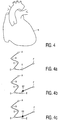
- Fig. 4 shows an illustration of a possible two-dimensional projection that can be output by the device as a simplified two-dimensional image 5.
- cardiac application it is a simplified basic image of a heart contour.
- the relevant clinical information can be added to this simplified image by means of Catmull-Rom splines.
- the course of the representation of a Catmull-Rom spline function is illustrated in fig. 4a .
- Six control points A, B, C, D, E, F, which can be displaced, are marked.
- An individual segment of the function graph for example a section extending between the points B and C, is defined by four consecutive control points, in this case the control points A to D.
- the outer control point that is to say A or F, is repeated in place of the fourth control point for the definition of the spline function. Consequently, by way of example the shape of the segment E-F is a function of the control points D to F.
- New arteries can be formed by using new spline control points, something which is possible, for example, via an input aid such as a mouse, a joystick or other drawing aids.
- Control points can be displaced, inserted and extinguished in order to vary the shape of an artery. It is possible in this case, for example, to click on the artery, which is illustrated by the spline function, in the near zone of one of its control points A, B, C, D, E, F, for example via a mouse, and to drag this near zone to a new site with the aid of the mouse.
- the control point is then displaced to the new site, the spline function on which the artery is based being correspondingly displaced. This displacement is terminated upon release of a depressed mouse key, for example.
- FIG. 5 A more elaborate presentation of an embodiment of a cardio-vascular tree is schematically given in Fig. 5 .
- the arteries 8 and 9 have been added to the template of fig. 4 .
- the device 1 is arranged to automatically assign the arteries 8 and 9 of the three-dimensional structure, which is illustrated only as a two-dimensional picture in fig. 5 , and to detect, for example which parts of said arteries 8, 9 are to be assigned to the front of the heart and which to the back of the heart.
- This assignment can be illustrated graphically on the monitor screen by lighter walls as contrasted with darker walls and can be performed without any action of a user.
- This assignment is possible in an automated fashion because the device 1 stores data according to their three-dimensional order. It is also possible, for example, to undertake a rotation of the anatomic structure in order thereby to view this structure from different directions.
- the artery 9 has been split up in fig. 5 into the individual segments 9a, 9b and 9c by inserted segment boundaries S1 and S2.
- the device 1 Given known names of the artery 9, the device 1 automatically names these individual segments in accordance with the nomenclature standard specified in fig. 1 , which is taken from the ACC/AHA Guidelines for Coronary Geography, Journal of the American College of Cardiology, Vol. 33, No. 6, 1999 .
- the position of the marked segment boundaries is included.
- the assignment of the branching 13 to the segment 9c is marked, so that it is then possible to output automatically in the patient report the point at which a sub-artery 14 inosculates with the main artery 9.
- junction 13 can then be displaced by the user, it being possible upon crossing of the segment boundary S2 or later S1 for the device 1 to rename automatically the position of the junction 13, without any action of the user.
- the text report would therefore automatically be adapted by the device 1, which recognizes the position of the sub-artery 14 relative to the main artery 9.
- the arteries are created by the indication of the control-points. All top-level arteries are constrained to the aorta. Their origin is forced to be within the boundary region of the aorta. Artery branches are created with reference to their parents, by indication of the connection point. This attachment position is converted to the branch-index along the destination spline. The discrimination of the arteries, as being connected to the aorta or as branches to other arteries is made on the basis of the position of the first point.
- the target spline In order to interact with an individual artery, the target spline must be selected, in which case it is highlighted. A specific spline can be selected by the user by input means. The selection can be made undone by selecting another spline or by any other appropriate way. By changing the relative position of the control points along the selected spline the coarse of the corresponding artery can be modified.
- the sub-artery 14 can be displaced relative to the main artery 9 by using the drawing aid to access the point of intersection 13 or its near zone and to displace it along the main artery. It is not necessary in this case to hit the point of intersection 13 exactly, instead it suffices for the near zone of the branching-off point 13 to be clicked on or the like.
- the position of the new point of intersection, which is formed at the new branching-off point 13', is calculated in such a way that said point lies in each case on the main artery 9.
- the branching-off point 13 for the sub-artery 14 is also moved in this case such that, as may be seen from the mathematical model in fig. 5b , the ratio of the distances of the branching-off point 13 from the control point B, compared with the distance of the branching-off point 13 from the control point C, automatically remains constant. Consequently, the change in the main artery due to a displacement, of the control point B here, by way of example, is automatically attended by a displacement of the branching-off point 13.
- the device also automatically changes all the names of the anatomical structures, for example of the arteries and sub-arteries, up to possibly newly set segment boundaries, thus rendering possible any desired change in shape by the user without the latter having to think about adapting the naming.
- Figs. 5c and 5d illustrate the insertion of new control points by clicking on the function graph, which stands schematically for an artery, outside the near zone of a control point.
- B2 a new control point
- the new control point B2 is inserted in fig. 5c between the previous control points B and C, specifically in such a way that it is positioned between the control point B and a branching-off point 13 for a sub-artery 14.
- the position of the branching-off point 13 is thereby automatically moved to the section between the control points B2 and C.
- a displacement of the point B for example, would be insignificant for the position of the branching-off point 13 below.
- removing an artery sub-tree simply involves removing the corresponding branch from its parent list.
- a selected artery sub-tree can be moved relative to its parent artery by a modification of its branch index.
- Pasting/copying of a sub-tree to a destination artery can be done by attaching the sub-tree to a destination artery at a given index, which can be calculated from the indicated destination position.
- Fig. 6 presents in a schematic way an embodiment of annotations added to an image of the anatomical structure being examined. It is likewise possible to use a menu to select from a group of abnormalities, for example occlusions (lesions), calcifications, thrombus, ectasia, dissections. It is possible to arrange the hierarchical data structure in such a way that every artery contains an annotation list. Each annotation has a start and an end index position. By using these index positions the annotated elements are tagged to the geometry of the arteries. If a spatial position of an artery is modified by user interaction the corresponding annotation is moved accordingly due to its index, being referred to the index of the artery.
- occlusions lesions
- calcifications calcifications
- thrombus thrombus
- ectasia ectasia
- a blood flow 21 can be shown in each case downstream of an abnormality, for example the occlusion 20 marked in fig. 14, the length of which can be marked in the illustration and is evaluated by the device 1. It is possible in this process to calculate a complete arterial occlusion or a partial arterial occlusion, and to output it via the output means.
- the blood flow is shown variously, as appropriate.
- the vessel 21 no longer supplied with blood is illustrated in fig. 14 as a dashed line.
- a restoration of a vessel section no longer supplied with blood per se can also be represented in an automated fashion by the device 1 via grafts or similar auxiliary lines from another main artery. For example, to restore the supply of the regions 21 otherwise no longer supplied with blood an additional vessel 22 can be introduced.
- the region 21 then acquires a representation which makes clear, on the one hand, that it is no longer being regularly supplied and that, on the other hand, supply has been restored via a bypass line 22. It is thereby possible, for example, for the measure that is to be taken in an operation to be simulated in advance. It is also possible to show the region 21 lying at the back surface of the heart. Additionally, collaterals can be marked, which can be performed in an automatic way. Each of the marked abnormalities is recorded with regard to its dimensions and severity (percentage value) and can also be represented with the aid of these data with more precise localization from the graphics in the text report.
- the data produced in the visualization can be stored in a database, denoted there as Cardiology Information System Data Base.
- the data stored there are also available for external applications such as, for example, document editors, mail tools, browsers for the Internet etc.
- the information is available not only as graphic data, but also, via its storage in the database, as text files for statistical analyses and the like, there being no need for any graphical evaluations for applications of this sort.
- the data obtained can therefore be exchanged between completely different systems, for example, beyond frontiers, without it being necessary to accommodate a possible plurality of medical or scientific processing teams.
- the anatomical structures are stored in the database as network models and are assigned clearly via their position, dimensions and their nomenclature.
- the arterial length is calculated in each case along the spline functions, and a respective point thereon is stored as a percentage of the total length from the start of an artery at the aorta up to its point (apex) lying remote therefrom.
- the lengths of the arterial segments and any abnormal elements are marked and stored in the same way by their relative position.
- the position of sub-arteries and diseased features is stored via their respective relative position, with reference to the length of the higher-level structure, for example the artery, in the direction of the blood flow.
- the origin of a sub-artery or the midpoint of a pathological disorder is used for this purpose.
- the graphics part 30 (Coronary Artery System Tool) is available as a plug-in component of the respective database 32.
- the plug-in component 31 can be arranged to make customised annotations of data, which are not obligatory for the graphics part.
- the graphics part 30 is arranged to make an association to a respective parameter in the database 32. Therefore, the changes made in the graphics part 30 are automatically updated in the database 32 and can be reported correctly, for example by means of a text report. This automatically creates an interface for incorporating the data into the system of the respective hospital 32. The actual device need not be changed for this purpose.
- the graphics data can be created, for example, by CAST as a Bynary Large Object (Blob) or in the XML format, and be incorporated in these formats into the respective individual patient database and can be made available for external applications 33.
Landscapes
- Engineering & Computer Science (AREA)
- Medical Informatics (AREA)
- Physics & Mathematics (AREA)
- Health & Medical Sciences (AREA)
- Public Health (AREA)
- Primary Health Care (AREA)
- Computer Graphics (AREA)
- Databases & Information Systems (AREA)
- Epidemiology (AREA)
- General Health & Medical Sciences (AREA)
- Data Mining & Analysis (AREA)
- Biomedical Technology (AREA)
- Pathology (AREA)
- Geometry (AREA)
- Software Systems (AREA)
- General Physics & Mathematics (AREA)
- Theoretical Computer Science (AREA)
- Measuring And Recording Apparatus For Diagnosis (AREA)
- Apparatus For Radiation Diagnosis (AREA)
- Processing Or Creating Images (AREA)
- Image Generation (AREA)
Claims (8)
- Dispositif (1) pour décrire et évaluer une structure anatomique tridimensionnelle, le dispositif comprenant :- un moyen d'entrée (2) pour entrer des données d'examen individuelles de ladite structure anatomique,- un moyen de sortie (3 ; 4) pour délivrer en sortie une image bidimensionnelle simplifiée (5) de ladite structure anatomique sur la base d'un modèle d'image pré-stocké comprenant un modèle graphique de structures cliniquement pertinentes de ladite structure anatomique, dans lequel ledit modèle d'image pré-stocké utilise une structure de données hiérarchique pour modéliser les structures cliniquement pertinentes, ledit dispositif étant agencé pour :- compléter graphiquement ladite image avec des détails individualisés (7), et- effectuer une affectation automatisée des détails individualisés (7) à ladite structure anatomique dans ladite image bidimensionnelle simplifiée,dans lequel la structure anatomique comprend un coeur et les détails (7) comprennent un système cardiovasculaire (8 ; 9 ; 11; 14; 15 ; 16; 17 ; 18 ; 19) comprenant des artères coronaires,
ledit dispositif étant en outre agencé pour diviser des images des artères (8 ; 9 ; 5 11 ; 14 ; 15 ; 16 ; 17 ; 18 ; 19) en segments individuels (9a ; 9b ; 9c) et entreprendre une désignation automatisée des segments (9a ; 9b ; 9c) des artères coronaires (8 ; 9; 11 ; 14 ; 15 ; 16 ; 17 ; 18 ; 19). - Dispositif selon la revendication 1, dans lequel ledit dispositif comprend un moyen d'évaluation conçu pour évaluer de manière automatisée la forme, la taille, la nomenclature et/ou le type des détails (7), ledit dispositif comprenant en outre un moyen conçu pour produire un rapport de texte comprenant des résultats d'évaluation.
- Dispositif selon l'une des revendications 1 ou 2, dans lequel le dispositif (1) est agencé pour entreprendre une modification automatisée d'informations alphanumériques des détails (7) ou de leurs parties.
- Dispositif selon l'une des revendications 1 à 3, dans lequel le dispositif est conçu pour entreprendre une affectation automatisée des détails (7) à une surface avant ou arrière de la structure anatomique.
- Dispositif selon l'une des revendications 1 à 4, dans lequel le dispositif (1) est conçu pour effectuer un calcul automatisé d'une fonctionnalité de la structure anatomique en référence à des régions anormales (21 ; 24).
- Dispositif selon la revendication 1, dans lequel le dispositif est en outre agencé pour sélectionner le modèle d'image pré-stocké parmi une pluralité de modèles d'image sur la base de la reconnaissance d'image automatique des données d'examen individuelles.
- Procédé de description et d'évaluation d'une structure anatomique tridimensionnelle, comprenant les étapes consistant à :- effectuer une entrée de données d'examen individuelles de ladite structure anatomique au moyen d'un moyen d'entrée dans un dispositif pour traiter les données,- effectuer une délivrance en sortie d'une image bidimensionnelle simplifiée de ladite structure anatomique sur la base d'un modèle d'image pré-stocké comprenant un modèle graphique de structures cliniquement pertinentes de ladite structure anatomique au moyen d'un moyen de délivrance en sortie, dans lequel ledit modèle d'image pré-stocké utilise une structure de données hiérarchique pour la modélisation des structures cliniquement pertinentes,- compléter graphiquement l'image bidimensionnelle simplifiée par des détails individualisés, et- effectuer une affectation automatisée des détails individualisés à ladite structure anatomique dans ladite image bidimensionnelle simplifiée,dans lequel la structure anatomique comprend un coeur et les détails (7) comprennent un système cardiovasculaire (8 ; 9 ; 11 ; 14 ; 15 ; 16 ; 17 ; 18 ; 19) comprenant des artères coronaires,
ledit procédé consistant en outre à diviser des images des artères (8 ; 9 ; 5 11 ; 14 ; 15 ; 16 ; 17 ; 18 ; 19) en segments individuels (9a ; 9b ; 9c) et à entreprendre une désignation automatisée des segments (9a ; 9b ; 9c) des artères coronaires (8; 9; 11 ; 14 ; 15 ; 16 ; 17 ; 18 ; 19). - Programme informatique pour décrire et évaluer une structure anatomique tridimensionnelle, ledit programme pouvant être utilisé pour :- effectuer une entrée de données d'examen individuelles de ladite structure anatomique,- effectuer une délivrance en sortie d'une image bidimensionnelle simplifiée de ladite structure anatomique sur la base d'un modèle d'image pré-stocké comprenant un modèle graphique de structures cliniquement pertinentes de ladite structure anatomique, ledit modèle d'image pré-stocké utilisant une structure de données hiérarchique pour la modélisation les structures cliniquement pertinentes,- compléter graphiquement l'image bidimensionnelle simplifiée par des détails individualisés, et- effectuer une affectation automatisée des détails individualisés à ladite structure anatomique dans ladite image bidimensionnelle simplifiée,dans lequel la structure anatomique comprend un coeur et les détails (7) comprennent un système cardiovasculaire (8 ; 9 ; 11; 14; 15 ; 16; 17 ; 18 ; 19) comprenant des artères coronaires,
ledit programme pouvant en outre être utilisé pour diviser les images des artères (8 ; 9 ; 5 11 ; 14 ; 15 ; 16 ; 17 ; 18 ; 19) en segments individuels (9a ; 9b ; 9c) et entreprendre une désignation automatisée des segments (9a ; 9b ; 9c) des artères coronaires (8; 9; 11 ; 14 ; 15 ; 16 ; 17 ; 18 ; 19).
Priority Applications (1)
| Application Number | Priority Date | Filing Date | Title |
|---|---|---|---|
| EP02713138.2A EP1377938B1 (fr) | 2001-04-02 | 2002-03-28 | Modelisation d'un coeur a l'aide d'un modele |
Applications Claiming Priority (4)
| Application Number | Priority Date | Filing Date | Title |
|---|---|---|---|
| EP01201200 | 2001-04-02 | ||
| EP01201200 | 2001-04-02 | ||
| PCT/IB2002/001042 WO2002080108A1 (fr) | 2001-04-02 | 2002-03-28 | Modelisation d'un coeur a l'aide d'un modele |
| EP02713138.2A EP1377938B1 (fr) | 2001-04-02 | 2002-03-28 | Modelisation d'un coeur a l'aide d'un modele |
Publications (2)
| Publication Number | Publication Date |
|---|---|
| EP1377938A1 EP1377938A1 (fr) | 2004-01-07 |
| EP1377938B1 true EP1377938B1 (fr) | 2018-12-26 |
Family
ID=8180092
Family Applications (1)
| Application Number | Title | Priority Date | Filing Date |
|---|---|---|---|
| EP02713138.2A Expired - Lifetime EP1377938B1 (fr) | 2001-04-02 | 2002-03-28 | Modelisation d'un coeur a l'aide d'un modele |
Country Status (4)
| Country | Link |
|---|---|
| US (1) | US7225011B2 (fr) |
| EP (1) | EP1377938B1 (fr) |
| JP (1) | JP4347571B2 (fr) |
| WO (1) | WO2002080108A1 (fr) |
Cited By (1)
| Publication number | Priority date | Publication date | Assignee | Title |
|---|---|---|---|---|
| CN109717953A (zh) * | 2019-02-01 | 2019-05-07 | 杭州晟视科技有限公司 | 一种血流量的确定方法、装置、电子设备和计算机存储介质 |
Families Citing this family (36)
| Publication number | Priority date | Publication date | Assignee | Title |
|---|---|---|---|---|
| US7689014B2 (en) * | 2000-01-18 | 2010-03-30 | Z-Kat Inc | Apparatus and method for measuring anatomical objects using coordinated fluoroscopy |
| US7526112B2 (en) * | 2001-04-30 | 2009-04-28 | Chase Medical, L.P. | System and method for facilitating cardiac intervention |
| WO2004057439A2 (fr) * | 2002-05-31 | 2004-07-08 | University Of Utah Research Foundation | Systeme et procede d'annotation visuelle et de representation des connaissances |
| EP1618509B1 (fr) | 2003-04-29 | 2012-04-18 | Cüneyt Konuralp | Procede et dispositif de codage segmental |
| FR2864669B1 (fr) * | 2003-12-24 | 2006-04-28 | Ge Med Sys Global Tech Co Llc | Procede pour ameliorer la visualisation d'un vaisseau |
| SE529153C2 (sv) * | 2005-01-25 | 2007-05-15 | Gripping Heart Ab | Hjärtklustertillståndsmaskin som simulerar hjärta och cirkulationssystemet för en individ |
| US7764817B2 (en) * | 2005-08-15 | 2010-07-27 | Siemens Medical Solutions Usa, Inc. | Method for database guided simultaneous multi slice object detection in three dimensional volumetric data |
| US8229545B2 (en) | 2005-09-15 | 2012-07-24 | St. Jude Medical, Atrial Fibrillation Division, Inc. | System and method for mapping complex fractionated electrogram information |
| US8038625B2 (en) * | 2005-09-15 | 2011-10-18 | St. Jude Medical, Atrial Fibrillation Division, Inc. | System and method for three-dimensional mapping of electrophysiology information |
| US8117549B2 (en) * | 2005-10-26 | 2012-02-14 | Bruce Reiner | System and method for capturing user actions within electronic workflow templates |
| DE102005061796A1 (de) * | 2005-12-23 | 2007-06-28 | Siemens Ag | Verfahren zur Modifikation einer Anzahl von Prozesssteuerungsprotokollen |
| US7804990B2 (en) * | 2006-01-25 | 2010-09-28 | Siemens Medical Solutions Usa, Inc. | System and method for labeling and identifying lymph nodes in medical images |
| US7988639B2 (en) * | 2006-05-17 | 2011-08-02 | St. Jude Medical, Atrial Fibrillation Division, Inc. | System and method for complex geometry modeling of anatomy using multiple surface models |
| SE530331C2 (sv) | 2006-06-02 | 2008-05-06 | Gripping Heart Ab | Gränssnittssystem för tillståndsmaskin |
| CN100399359C (zh) * | 2006-07-06 | 2008-07-02 | 上海交通大学 | 用动态数字模型检测ct血管造影术重建算法性能的方法 |
| US7912270B2 (en) * | 2006-11-21 | 2011-03-22 | General Electric Company | Method and system for creating and using an impact atlas |
| US8023709B2 (en) * | 2006-11-24 | 2011-09-20 | General Electric Company | Vasculature partitioning methods and apparatus |
| JP2008161277A (ja) * | 2006-12-27 | 2008-07-17 | Hitachi Ltd | 血管情報管理装置 |
| US8406860B2 (en) | 2008-01-25 | 2013-03-26 | Novadaq Technologies Inc. | Method for evaluating blush in myocardial tissue |
| JP5476317B2 (ja) * | 2008-01-25 | 2014-04-23 | ノバダック テクノロジーズ インコーポレイテッド | 心筋組織におけるブラッシュを評価する方法及びシステム |
| US8560968B1 (en) * | 2009-03-26 | 2013-10-15 | Vinod Nair | Method and apparatus for evaluating a heart patient |
| US20110182493A1 (en) * | 2010-01-25 | 2011-07-28 | Martin Huber | Method and a system for image annotation |
| JP5584006B2 (ja) * | 2010-03-31 | 2014-09-03 | 富士フイルム株式会社 | 投影画像生成装置、投影画像生成プログラムおよび投影画像生成方法 |
| JP6028096B2 (ja) | 2012-06-21 | 2016-11-16 | ノバダック テクノロジーズ インコーポレイテッド | 血管造影及びかん流の定量化並びに解析手法 |
| US10993628B2 (en) | 2013-10-25 | 2021-05-04 | Philips Image Guided Therapy Corporation | Devices, systems, and methods for vessel assessment |
| US9754082B2 (en) * | 2014-05-30 | 2017-09-05 | Heartflow, Inc. | Systems and methods for reporting blood flow characteristics |
| CN107209118B (zh) | 2014-09-29 | 2021-05-28 | 史赛克欧洲运营有限公司 | 在自体荧光存在下生物材料中目标荧光团的成像 |
| EP3203902B1 (fr) | 2014-10-09 | 2021-07-07 | Novadaq Technologies ULC | Quantification de circulation sanguine absolue dans un tissu à l'aide de photopléthysmographie induite par fluorescence |
| JP2016158829A (ja) * | 2015-02-27 | 2016-09-05 | 富士フイルム株式会社 | 医用画像表示制御装置および方法並びにプログラム |
| WO2018054762A1 (fr) * | 2016-09-23 | 2018-03-29 | Koninklijke Philips N.V. | Système et procédé d'évaluation de l'obstruction d'une voie d'éjection du cœur d'un sujet |
| JP6975235B2 (ja) | 2016-11-22 | 2021-12-01 | コーニンクレッカ フィリップス エヌ ヴェKoninklijke Philips N.V. | 生物物理的シミュレーション用の血管樹標準化及び/又はプルーニングされた部分用の拡張シミュレーション |
| CA3049922A1 (fr) | 2017-02-10 | 2018-08-16 | Novadaq Technologies ULC | Systemes et procedes d'imagerie a fluorescence portative a champ ouvert |
| JP2019149124A (ja) * | 2018-02-28 | 2019-09-05 | 富士フイルム株式会社 | 変換装置、変換方法、及びプログラム |
| US10685445B2 (en) * | 2018-06-09 | 2020-06-16 | Uih-Rt Us Llc | Systems and methods for generating augmented segmented image set |
| US10922859B2 (en) * | 2018-10-15 | 2021-02-16 | Adobe Inc. | Vector art object deformation techniques |
| US11527329B2 (en) | 2020-07-28 | 2022-12-13 | Xifin, Inc. | Automatically determining a medical recommendation for a patient based on multiple medical images from multiple different medical imaging modalities |
Citations (1)
| Publication number | Priority date | Publication date | Assignee | Title |
|---|---|---|---|---|
| US5987345A (en) * | 1996-11-29 | 1999-11-16 | Arch Development Corporation | Method and system for displaying medical images |
Family Cites Families (15)
| Publication number | Priority date | Publication date | Assignee | Title |
|---|---|---|---|---|
| US4945478A (en) * | 1987-11-06 | 1990-07-31 | Center For Innovative Technology | Noninvasive medical imaging system and method for the identification and 3-D display of atherosclerosis and the like |
| FR2636451A1 (fr) * | 1988-09-13 | 1990-03-16 | Gen Electric Cgr | Procede de reconstruction d'arborescence a trois dimensions par etiquetage |
| EP0383697A3 (fr) * | 1989-02-17 | 1990-09-12 | Nihon Kohden Corporation | Simulateur d'un processus électrocardiographique |
| US5151856A (en) * | 1989-08-30 | 1992-09-29 | Technion R & D Found. Ltd. | Method of displaying coronary function |
| US5175733A (en) * | 1990-12-27 | 1992-12-29 | Intel Corporation | Adaptive message routing for multi-dimensional networks |
| FR2708166A1 (fr) * | 1993-07-22 | 1995-01-27 | Philips Laboratoire Electroniq | Procédé de traitement d'images numérisées pour la détection automatique de sténoses. |
| US5734739A (en) * | 1994-05-31 | 1998-03-31 | University Of Washington | Method for determining the contour of an in vivo organ using multiple image frames of the organ |
| US5715449A (en) * | 1994-06-20 | 1998-02-03 | Oceania, Inc. | Method for generating structured medical text through user selection of displayed text and rules |
| US5889524A (en) * | 1995-09-11 | 1999-03-30 | University Of Washington | Reconstruction of three-dimensional objects using labeled piecewise smooth subdivision surfaces |
| US6047080A (en) * | 1996-06-19 | 2000-04-04 | Arch Development Corporation | Method and apparatus for three-dimensional reconstruction of coronary vessels from angiographic images |
| US6047090A (en) * | 1996-07-31 | 2000-04-04 | U.S. Philips Corporation | Method and device for automatic segmentation of a digital image using a plurality of morphological opening operation |
| US6106466A (en) | 1997-04-24 | 2000-08-22 | University Of Washington | Automated delineation of heart contours from images using reconstruction-based modeling |
| US6073042A (en) * | 1997-09-25 | 2000-06-06 | Siemens Medical Systems, Inc. | Display of three-dimensional MRA images in which arteries can be distinguished from veins |
| IT1297396B1 (it) * | 1997-12-30 | 1999-09-01 | Francesco Buzzigoli | Metodo e dispositivo per la ricostruzione di immagini tridimensionali di vasi sanguigni, in particolare di arterie coronarie, o di altre |
| DE69921154T2 (de) * | 1998-08-14 | 2005-11-10 | Frank S. London Prato | Anwendung von streu- und abschwächungs-korrekturen auf emissions-tomographie-bildern unter verwendung von einer atlas-abgeleiteten anatomie |
-
2002
- 2002-03-28 EP EP02713138.2A patent/EP1377938B1/fr not_active Expired - Lifetime
- 2002-03-28 WO PCT/IB2002/001042 patent/WO2002080108A1/fr not_active Ceased
- 2002-03-28 US US10/296,868 patent/US7225011B2/en not_active Expired - Lifetime
- 2002-03-28 JP JP2002578254A patent/JP4347571B2/ja not_active Expired - Fee Related
Patent Citations (1)
| Publication number | Priority date | Publication date | Assignee | Title |
|---|---|---|---|---|
| US5987345A (en) * | 1996-11-29 | 1999-11-16 | Arch Development Corporation | Method and system for displaying medical images |
Non-Patent Citations (2)
| Title |
|---|
| "CVRMed-MRCAS'97", vol. 1205, 1 January 1997, SPRINGER-VERLAG, Berlin/Heidelberg, ISBN: 97835406273410, article THOMAS BERLAGE ET AL: "Augmented reality for diagnosis based on ultrasound images", pages: 253 - 262, XP055048528, DOI: 10.1007/BFb0029244 * |
| THOMAS BERLAGE: "Augmented-Reality Communication for Diagnostic Tasks in Cardiology", IEEE TRANSACTIONS ON INFORMATION TECHNOLOGY IN BIOMEDICINE, IEEE SERVICE CENTER, LOS ALAMITOS, CA, US, vol. 2, no. 3, 1 September 1998 (1998-09-01), XP011028309, ISSN: 1089-7771 * |
Cited By (1)
| Publication number | Priority date | Publication date | Assignee | Title |
|---|---|---|---|---|
| CN109717953A (zh) * | 2019-02-01 | 2019-05-07 | 杭州晟视科技有限公司 | 一种血流量的确定方法、装置、电子设备和计算机存储介质 |
Also Published As
| Publication number | Publication date |
|---|---|
| US20040002660A1 (en) | 2004-01-01 |
| EP1377938A1 (fr) | 2004-01-07 |
| JP4347571B2 (ja) | 2009-10-21 |
| WO2002080108A1 (fr) | 2002-10-10 |
| JP2004519306A (ja) | 2004-07-02 |
| US7225011B2 (en) | 2007-05-29 |
Similar Documents
| Publication | Publication Date | Title |
|---|---|---|
| EP1377938B1 (fr) | Modelisation d'un coeur a l'aide d'un modele | |
| US12138027B2 (en) | System for vascular assessment | |
| US20220359063A1 (en) | Systems and methods for processing electronic images to determine a planar mapping | |
| Yoo et al. | 3D printing in surgical management of double outlet right ventricle | |
| Viceconti et al. | The multimod application framework: a rapid application development tool for computer aided medicine | |
| RU2451335C2 (ru) | Приложения для эффективной диагностики, зависимые от изображения и контекста, относящиеся к анатомии | |
| US9773347B2 (en) | Interacting with a three-dimensional object dataset | |
| Zhang | Virtual reality technology | |
| Simmons-Ehrhardt | Open osteology: Medical imaging databases as skeletal collections | |
| EP3475861A1 (fr) | Évaluation d'arbre de décision utilisant une ontologie | |
| US8503741B2 (en) | Workflow of a service provider based CFD business model for the risk assessment of aneurysm and respective clinical interface | |
| Giachetti et al. | Reconstruction and web distribution of measurable arterial models | |
| Gielow et al. | Virtual intravascular visualization of the aorta for surgical planning in acute type A aortic dissection | |
| Kunert et al. | An interactive system for volume segmentation in computer-assisted surgery | |
| Cai et al. | Simulation-based virtual prototyping of customized catheterization devices | |
| Wahle et al. | A new 3-D attributed data model for archiving and interchanging of coronary vessel systems | |
| Palak et al. | 3D Segmentation and Visualization of Human Brain CT Images for Surgical Training-A VTK Approach | |
| Huang et al. | IVME: A tool for editing, manipulation, quantification, and labeling of cerebrovascular models | |
| Dong et al. | User centered design for medical visualization | |
| US20230245376A1 (en) | System and method for four-dimensional angiography | |
| HK40102398A (en) | System for vascular assessment | |
| Wischgoll et al. | A quantitative analysis tool for cardiovascular systems | |
| Kose et al. | Comprehensive combined visualization of anatomy and hemodynamics |
Legal Events
| Date | Code | Title | Description |
|---|---|---|---|
| PUAI | Public reference made under article 153(3) epc to a published international application that has entered the european phase |
Free format text: ORIGINAL CODE: 0009012 |
|
| 17P | Request for examination filed |
Effective date: 20031103 |
|
| AK | Designated contracting states |
Kind code of ref document: A1 Designated state(s): AT BE CH CY DE DK ES FI FR GB GR IE IT LI LU MC NL PT SE TR |
|
| AX | Request for extension of the european patent |
Extension state: AL LT LV MK RO SI |
|
| 17Q | First examination report despatched |
Effective date: 20130122 |
|
| RAP1 | Party data changed (applicant data changed or rights of an application transferred) |
Owner name: KONINKLIJKE PHILIPS N.V. |
|
| GRAP | Despatch of communication of intention to grant a patent |
Free format text: ORIGINAL CODE: EPIDOSNIGR1 |
|
| STAA | Information on the status of an ep patent application or granted ep patent |
Free format text: STATUS: GRANT OF PATENT IS INTENDED |
|
| INTG | Intention to grant announced |
Effective date: 20180803 |
|
| GRAS | Grant fee paid |
Free format text: ORIGINAL CODE: EPIDOSNIGR3 |
|
| GRAA | (expected) grant |
Free format text: ORIGINAL CODE: 0009210 |
|
| STAA | Information on the status of an ep patent application or granted ep patent |
Free format text: STATUS: THE PATENT HAS BEEN GRANTED |
|
| AK | Designated contracting states |
Kind code of ref document: B1 Designated state(s): AT BE CH CY DE DK ES FI FR GB GR IE IT LI LU MC NL PT SE TR |
|
| REG | Reference to a national code |
Ref country code: GB Ref legal event code: FG4D |
|
| REG | Reference to a national code |
Ref country code: CH Ref legal event code: EP |
|
| REG | Reference to a national code |
Ref country code: AT Ref legal event code: REF Ref document number: 1082479 Country of ref document: AT Kind code of ref document: T Effective date: 20190115 |
|
| REG | Reference to a national code |
Ref country code: DE Ref legal event code: R096 Ref document number: 60249738 Country of ref document: DE |
|
| REG | Reference to a national code |
Ref country code: IE Ref legal event code: FG4D |
|
| PG25 | Lapsed in a contracting state [announced via postgrant information from national office to epo] |
Ref country code: FI Free format text: LAPSE BECAUSE OF FAILURE TO SUBMIT A TRANSLATION OF THE DESCRIPTION OR TO PAY THE FEE WITHIN THE PRESCRIBED TIME-LIMIT Effective date: 20181226 |
|
| PGFP | Annual fee paid to national office [announced via postgrant information from national office to epo] |
Ref country code: FR Payment date: 20190328 Year of fee payment: 18 Ref country code: GB Payment date: 20190327 Year of fee payment: 18 |
|
| REG | Reference to a national code |
Ref country code: NL Ref legal event code: MP Effective date: 20181226 |
|
| PG25 | Lapsed in a contracting state [announced via postgrant information from national office to epo] |
Ref country code: SE Free format text: LAPSE BECAUSE OF FAILURE TO SUBMIT A TRANSLATION OF THE DESCRIPTION OR TO PAY THE FEE WITHIN THE PRESCRIBED TIME-LIMIT Effective date: 20181226 Ref country code: GR Free format text: LAPSE BECAUSE OF FAILURE TO SUBMIT A TRANSLATION OF THE DESCRIPTION OR TO PAY THE FEE WITHIN THE PRESCRIBED TIME-LIMIT Effective date: 20190327 |
|
| REG | Reference to a national code |
Ref country code: AT Ref legal event code: MK05 Ref document number: 1082479 Country of ref document: AT Kind code of ref document: T Effective date: 20181226 |
|
| PG25 | Lapsed in a contracting state [announced via postgrant information from national office to epo] |
Ref country code: NL Free format text: LAPSE BECAUSE OF FAILURE TO SUBMIT A TRANSLATION OF THE DESCRIPTION OR TO PAY THE FEE WITHIN THE PRESCRIBED TIME-LIMIT Effective date: 20181226 |
|
| PG25 | Lapsed in a contracting state [announced via postgrant information from national office to epo] |
Ref country code: IT Free format text: LAPSE BECAUSE OF FAILURE TO SUBMIT A TRANSLATION OF THE DESCRIPTION OR TO PAY THE FEE WITHIN THE PRESCRIBED TIME-LIMIT Effective date: 20181226 Ref country code: ES Free format text: LAPSE BECAUSE OF FAILURE TO SUBMIT A TRANSLATION OF THE DESCRIPTION OR TO PAY THE FEE WITHIN THE PRESCRIBED TIME-LIMIT Effective date: 20181226 Ref country code: PT Free format text: LAPSE BECAUSE OF FAILURE TO SUBMIT A TRANSLATION OF THE DESCRIPTION OR TO PAY THE FEE WITHIN THE PRESCRIBED TIME-LIMIT Effective date: 20190426 |
|
| PGFP | Annual fee paid to national office [announced via postgrant information from national office to epo] |
Ref country code: DE Payment date: 20190528 Year of fee payment: 18 |
|
| REG | Reference to a national code |
Ref country code: DE Ref legal event code: R097 Ref document number: 60249738 Country of ref document: DE |
|
| PG25 | Lapsed in a contracting state [announced via postgrant information from national office to epo] |
Ref country code: AT Free format text: LAPSE BECAUSE OF FAILURE TO SUBMIT A TRANSLATION OF THE DESCRIPTION OR TO PAY THE FEE WITHIN THE PRESCRIBED TIME-LIMIT Effective date: 20181226 Ref country code: DK Free format text: LAPSE BECAUSE OF FAILURE TO SUBMIT A TRANSLATION OF THE DESCRIPTION OR TO PAY THE FEE WITHIN THE PRESCRIBED TIME-LIMIT Effective date: 20181226 Ref country code: MC Free format text: LAPSE BECAUSE OF FAILURE TO SUBMIT A TRANSLATION OF THE DESCRIPTION OR TO PAY THE FEE WITHIN THE PRESCRIBED TIME-LIMIT Effective date: 20181226 |
|
| REG | Reference to a national code |
Ref country code: CH Ref legal event code: PL |
|
| PLBE | No opposition filed within time limit |
Free format text: ORIGINAL CODE: 0009261 |
|
| STAA | Information on the status of an ep patent application or granted ep patent |
Free format text: STATUS: NO OPPOSITION FILED WITHIN TIME LIMIT |
|
| PG25 | Lapsed in a contracting state [announced via postgrant information from national office to epo] |
Ref country code: LU Free format text: LAPSE BECAUSE OF NON-PAYMENT OF DUE FEES Effective date: 20190328 |
|
| 26N | No opposition filed |
Effective date: 20190927 |
|
| REG | Reference to a national code |
Ref country code: BE Ref legal event code: MM Effective date: 20190331 |
|
| PG25 | Lapsed in a contracting state [announced via postgrant information from national office to epo] |
Ref country code: IE Free format text: LAPSE BECAUSE OF NON-PAYMENT OF DUE FEES Effective date: 20190328 Ref country code: CH Free format text: LAPSE BECAUSE OF NON-PAYMENT OF DUE FEES Effective date: 20190331 Ref country code: LI Free format text: LAPSE BECAUSE OF NON-PAYMENT OF DUE FEES Effective date: 20190331 |
|
| PG25 | Lapsed in a contracting state [announced via postgrant information from national office to epo] |
Ref country code: BE Free format text: LAPSE BECAUSE OF NON-PAYMENT OF DUE FEES Effective date: 20190331 |
|
| PG25 | Lapsed in a contracting state [announced via postgrant information from national office to epo] |
Ref country code: TR Free format text: LAPSE BECAUSE OF FAILURE TO SUBMIT A TRANSLATION OF THE DESCRIPTION OR TO PAY THE FEE WITHIN THE PRESCRIBED TIME-LIMIT Effective date: 20181226 |
|
| REG | Reference to a national code |
Ref country code: DE Ref legal event code: R119 Ref document number: 60249738 Country of ref document: DE |
|
| PG25 | Lapsed in a contracting state [announced via postgrant information from national office to epo] |
Ref country code: FR Free format text: LAPSE BECAUSE OF NON-PAYMENT OF DUE FEES Effective date: 20200331 Ref country code: DE Free format text: LAPSE BECAUSE OF NON-PAYMENT OF DUE FEES Effective date: 20201001 |
|
| GBPC | Gb: european patent ceased through non-payment of renewal fee |
Effective date: 20200328 |
|
| PG25 | Lapsed in a contracting state [announced via postgrant information from national office to epo] |
Ref country code: GB Free format text: LAPSE BECAUSE OF NON-PAYMENT OF DUE FEES Effective date: 20200328 |
|
| PG25 | Lapsed in a contracting state [announced via postgrant information from national office to epo] |
Ref country code: CY Free format text: LAPSE BECAUSE OF FAILURE TO SUBMIT A TRANSLATION OF THE DESCRIPTION OR TO PAY THE FEE WITHIN THE PRESCRIBED TIME-LIMIT Effective date: 20181226 |