EP1378253A1 - Sterilisation mit durchströmbarem Behälter - Google Patents
Sterilisation mit durchströmbarem Behälter Download PDFInfo
- Publication number
- EP1378253A1 EP1378253A1 EP03254105A EP03254105A EP1378253A1 EP 1378253 A1 EP1378253 A1 EP 1378253A1 EP 03254105 A EP03254105 A EP 03254105A EP 03254105 A EP03254105 A EP 03254105A EP 1378253 A1 EP1378253 A1 EP 1378253A1
- Authority
- EP
- European Patent Office
- Prior art keywords
- container
- sterilant
- conduit
- chamber
- sterilization system
- Prior art date
- Legal status (The legal status is an assumption and is not a legal conclusion. Google has not performed a legal analysis and makes no representation as to the accuracy of the status listed.)
- Granted
Links
Images





Classifications
-
- A—HUMAN NECESSITIES
- A61—MEDICAL OR VETERINARY SCIENCE; HYGIENE
- A61L—METHODS OR APPARATUS FOR STERILISING MATERIALS OR OBJECTS IN GENERAL; DISINFECTION, STERILISATION OR DEODORISATION OF AIR; CHEMICAL ASPECTS OF BANDAGES, DRESSINGS, ABSORBENT PADS OR SURGICAL ARTICLES; MATERIALS FOR BANDAGES, DRESSINGS, ABSORBENT PADS OR SURGICAL ARTICLES
- A61L2/00—Disinfection or sterilisation of materials or objects, in general; Accessories therefor
- A61L2/16—Disinfection or sterilisation of materials or objects, in general; Accessories therefor using chemical substances
- A61L2/20—Gaseous substances, e.g. vapours
- A61L2/208—Hydrogen peroxide
-
- A—HUMAN NECESSITIES
- A61—MEDICAL OR VETERINARY SCIENCE; HYGIENE
- A61B—DIAGNOSIS; SURGERY; IDENTIFICATION
- A61B1/00—Instruments for performing medical examinations of the interior of cavities or tubes of the body by visual or photographical inspection, e.g. endoscopes; Illuminating arrangements therefor
- A61B1/12—Instruments for performing medical examinations of the interior of cavities or tubes of the body by visual or photographical inspection, e.g. endoscopes; Illuminating arrangements therefor with cooling or rinsing arrangements
- A61B1/121—Instruments for performing medical examinations of the interior of cavities or tubes of the body by visual or photographical inspection, e.g. endoscopes; Illuminating arrangements therefor with cooling or rinsing arrangements provided with means for cleaning post-use
- A61B1/123—Instruments for performing medical examinations of the interior of cavities or tubes of the body by visual or photographical inspection, e.g. endoscopes; Illuminating arrangements therefor with cooling or rinsing arrangements provided with means for cleaning post-use using washing machines
-
- A—HUMAN NECESSITIES
- A61—MEDICAL OR VETERINARY SCIENCE; HYGIENE
- A61B—DIAGNOSIS; SURGERY; IDENTIFICATION
- A61B90/00—Instruments, implements or accessories specially adapted for surgery or diagnosis and not covered by any of the groups A61B1/00 - A61B50/00, e.g. for luxation treatment or for protecting wound edges
- A61B90/70—Cleaning devices specially adapted for surgical instruments
- A61B2090/701—Cleaning devices specially adapted for surgical instruments for flexible tubular instruments, e.g. endoscopes
-
- A—HUMAN NECESSITIES
- A61—MEDICAL OR VETERINARY SCIENCE; HYGIENE
- A61L—METHODS OR APPARATUS FOR STERILISING MATERIALS OR OBJECTS IN GENERAL; DISINFECTION, STERILISATION OR DEODORISATION OF AIR; CHEMICAL ASPECTS OF BANDAGES, DRESSINGS, ABSORBENT PADS OR SURGICAL ARTICLES; MATERIALS FOR BANDAGES, DRESSINGS, ABSORBENT PADS OR SURGICAL ARTICLES
- A61L2202/00—Aspects relating to methods or apparatus for disinfecting or sterilising materials or objects
- A61L2202/10—Apparatus features
- A61L2202/12—Apparatus for isolating biocidal substances from the environment
- A61L2202/122—Chambers for sterilisation
Definitions
- the invention relates to sterilization of articles with a vapor sterilant, and more particularly to sterilization of articles in which the vapor sterilant is drawn through a container holding the articles.
- the low pressures (0.5 torr to 10.0 torr) inside of the chamber promotes quick diffusion of the sterilant vapor to all areas therein.
- improving the flow into the container can benefit the sterilization efficiency.
- Applicants have achieved this goal in a fashion which may be employed with most of the commercially available containers in a novel approach to employing parts of the sterilization cycle already present to flow some of the sterilant vapor through the container.
- a sterilization system comprises a sterilization chamber for receiving a container having an article to be sterilized therein.
- a source of sterilant connects to the sterilization chamber.
- a vacuum pump connects to the sterilization chamber. Either the source of sterilant, or the vacuum pump, or both, connect to the chamber via a one or more conduits having an interface with the container. This promotes ingress of sterilant into the container, sterilant may be flowed directly into the container via the conduit or exhausted from the chamber through the container via the conduit.
- the vacuum pump connects to the chamber via the conduit.
- the source of sterilant connects to the chamber via the conduit.
- both the vacuum pump and the source of sterilant connect to the chamber via the conduit, each of the vacuum pump and source of sterilant having a valve between itself and the conduit whereby to isolate itself from the conduit.
- the interface comprises an opening into the conduit and an opening into the container, the opening into the conduit being adjacent the opening into the container.
- the container need not attach to the conduit at the interface with a physical connection, but may merely be adjacent or abut at the interface.
- the sterilant comprises a chemical vapor sterilant.
- the interface is removable from the chamber.
- One advantage of this is to allow different interfaces to be used within the chamber for use with differently sized or shaped containers.
- the interface comprises a support upon which can rest the container, the support having one or more openings facing the container, the one or more openings being in fluid communication with the conduit.
- the support can have an upper surface upon which rests the container, with the one or more openings penetrating the upper surface.
- the manifold may have a plurality of supporting surfaces within the chamber upon which can rest the container and additional containers, with the interface having openings on the supporting surfaces into the manifold.
- the source of sterilant comprises a vaporizer in fluid communication with the chamber.
- the container has a manifold inside in fluid communication with the conduit and adapted to receive a lumened device therethrough whereby to promote ingress of sterilant through the lumened device.
- a method for sterilizing an article according to the present invention comprises the steps of:
- a conduit having an interface with the container leads to a vacuum pump and step a) is performed through the conduit.
- a conduit having an interface with the container and leads to a source of sterilant and step b) is performed through the conduit.
- the step of admitting the sterilant into the chamber can comprise vaporizing a sterilant solution to create a chemical vapor sterilant and further comprising the step of exhausting a portion of the sterilant through the container while admitting the vapor sterilant into the chamber.
- the container has an opening on a surface thereof and a conduit has an opening therein and the method includes the step of placing the opening on the container adjacent the opening on the conduit.
- the article comprises a lumen and the method includes the steps of providing a conduit having an interface with the container and leading to a vacuum pump and performing step a) through the conduit, connecting the lumen to a manifold in the container, and exhausting a portion of the sterilant through the lumen via the manifold.
- the method includes the steps of providing a conduit having an interface with the container and leading to a source of sterilant and performing step b) through the conduit, connecting the lumen to a manifold in the container, and introducing at least a portion of the sterilant through the lumen via the manifold.
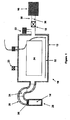
- FIG. 1 shows in block diagram form a sterilization system 10 comprising a sterilization chamber 12, a vaporizer 14, and a vacuum pump 16.
- the vacuum pump is capable of drawing a vacuum on the chamber, preferably as low as 0.5 torr.
- throttle valve 18 Between the vacuum pump 16 and the chamber 12, is preferably located at throttle valve 18 and optionally an orifice plate 20.
- the throttle valve 18 has good shut-off capability.
- a vent valve 23 employing a HEPA antimicrobial filter allows clean sterile air to enter the chamber 12.
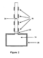
- the vaporizer 14 connects to the chamber 12 by means of an elongated diffusion path 24.
- the diffusion path 24 incorporates temperature control elements 26 to control the temperature along the diffusion path 24.
- Vaporizers suitable for vaporizing a Liquid sterilant such as hydrogen peroxide solution are known in the art.
- the vaporizer can comprise a small chamber into which the liquid hydrogen peroxide solution is injected. The low pressure in the vaporizer caused by the vacuum in the chamber causes the hydrogen peroxide solution to vaporize.
- the vaporizer 14 itself incorporates heating elements 28 which control the temperature in the vaporizer to optimize the vaporization process.
- some form of thermal insulation 30 provided at the interface so that the high temperatures of the vaporizer 14 will not unduly affect the temperature in the diffusion path 24.
- the vaporizer 14 and diffusion path 24 are preferably formed of aluminum; the thermal insulation 30 can take the form of a polyvinyl chloride (PVC) joint connecting the two together.
- a heater 32 inside the chamber 12, preferably near a lower portion of the chamber 12 for revaporizing condensed hydrogen peroxide inside the chamber 12.
- the chamber 12 preferably includes a mechanism (not shown) to create a plasma therein.
- a mechanism can include a source of radio or low frequency energy as described by Jacobs et al. U.S. Patent No. 4,643,867,or by Platt, Jr. et al. in published U.S. Application Document No. 20020068012, both of which are incorporated herein by reference.
- the present invention achieves its beneficial effect by allowing some of the hydrogen peroxide which is vaporized out of solution in the vaporizer 14 to condense onto the diffusion path 24. After most of the hydrogen peroxide solution has vaporized, the temperature control elements 26 raise the temperature of the diffusion path to allow the condensed hydrogen peroxide to re-vaporize. Water has a higher vapor pressure than hydrogen peroxide, thus hydrogen peroxide in the vapor condenses more easily than water. Thus, the material which condenses in the diffusion path will have a higher concentration of hydrogen peroxide than the starting concentration of the hydrogen peroxide solution in the vaporizer 14.
- the temperature control elements 26 in simple form can comprise mere electric resistance heaters.
- the low ambient temperature of the diffusion path 24 provides the low temperature for condensing hydrogen peroxide thereon, and the control elements 26 later heat the diffusion path 24 to re-vaporize the now more highly concentrated hydrogen peroxide from the diffusion path 24.
- the temperature control elements 26 can further comprise a chilling component to lower the temperature of the diffusion path below ambient. Suitable chilling components include thermoelectric coolers or a typical mechanical refrigeration system.
- the diffusion path 24 would be first chilled, preferably to about 10°C, and then some time after vaporization has begun or even after it has completed, the diffusion path 24 is then heated, preferably up to 50°C or 110°C.
- the diffusion path 24 can potentially cause the vaporizing sterilant to condense in cooler regions between the temperature control elements 26 and then re-vaporize as it passes the temperature-control element 26.
- the efficacy tests were conducted by placing a CSR-wrapped tray (3.5"x10"x20") consisting of representative medical devices and test lumens in a 20-liter aluminum chamber (4.4"x12"x22").
- a one-inch stainless steel wire inoculated with at least 1x10 6 Bacillus stearothermophilus spores was placed in the center of each of the test lumens.
- the effects with and without temperature control of the diffusion path were investigated with both a TEFLON, poly(tetrafluoroethylene)lumen having an internal diameter of 1mm and a length of 700mm, and a stainless steel lumen having an internal diameter of 1mm, and a length of 500mm. All lumens were open at both ends.
- each of the samples were subjected to a sterilization cycle in a 20 liter vacuum chamber, which was held at 40°C and 3 torr for 5 minutes. 1.44 ml of a 59% solution of hydrogen peroxide in water was injected into the vaporizer which was held at 60°C. The 5 minute clock then started and the chamber was pumped down to 3 torr, which took less than one minute.
- the diffusion path 24 had an initial temperature of 30°C for the first minute while the chamber was evacuated to 3 torr and was then heated to 50°C to release the condensed peroxide from the diffusion path into the chamber for the remainder of the cycle while pressure was maintained at 3 torr. In the other case, the diffusion path was held at 50°C throughout the cycle.
- the temperature control elements 26 in simple form heating elements, are spaced apart from one another. Also, preferably, the diffusion path 24 is vertical in this respect. As the hydrogen peroxide solution vaporizes and passes through the diffusion path 24, it is thought that it may alternately condense and re-vaporize as it passes over the heated and unheated sections of the diffusion path 24.
- the diffusion path could alternatively comprise alternating heating and cooling elements.
- the heater 32 within the chamber 12 acts similarly to the heating of the diffusion path 24. By controlling the heater 32 temperature, the peroxide can be first condensed on the heater 32 and then re-vaporized into the chamber 12 to concentrate the peroxide.
- a preferred cycle would be a modification of a cycle described in the Wu et al. U.S. Patent No. 6,365,102, incorporated herein by reference.
- a series of pre-plasma energy additions with venting in-between dries moisture from the chamber 12.
- a vacuum is then drawn upon the chamber 12 and the hydrogen peroxide solution injected into the vaporizer 14.
- the peroxide solution can also be injected at atmospheric pressure.
- Some of the vaporizing solution condenses upon the cool diffusion path 24. After a time sufficient for most or all of the hydrogen peroxide solution to vaporize from the vaporizer 14, the diffusion path 24 is warmed by the temperature control elements 26 and the condensed hydrogen peroxide solution re-vaporizes.
- the throttle valve 18 is closed and the pump 16 turned off to seal the chamber 12.
- Much of the water fraction of the hydrogen peroxide solution has thus been drawn out of the chamber 12 by the vacuum pump 16 and the remaining hydrogen peroxide solution which re-vaporizes from the diffusion path 24, or from the heater 32 in the chamber 12 if present, is of a higher hydrogen peroxide concentration than the starting solution.
- a computer based control system (not shown) controls the functions of the process for ease and repeatability.
- the hydrogen peroxide vapor thus produced contacts an article 34 or articles 34 in the chamber 12 and effects sterilization thereof. If those articles 34 have diffusion restricted areas, such as long, narrow lumens, it may be preferable to then vent the chamber 12 and allow clean sterile air therein to drive the hydrogen peroxide vapor deeper into the diffusion restricted areas. Then the chamber 12 is again subjected to vacuum and an additional injection of hydrogen peroxide, preferably with the heating sequence on the diffusion path, is repeated. After a time period sufficient to effect sterilization of the article 34, preferably with a six-log reduction in challenge organisms such as Bacillus stearothermophilus, a plasma is lit within the chamber 12, thereby enhancing the sterilization and breaking down the hydrogen peroxide into water and oxygen,
- the orifice plate 20 can enhance the effect of concentrating the hydrogen peroxide during its vaporization.
- a controlled or slow pump-down of the chamber 12 initially draws off more water than hydrogen peroxide from solution as the water has a higher vapor pressure, thereby leaving a higher concentration hydrogen peroxide behind. Controlling the pump-down can be difficult as vacuum pumps generally do not throttle back well and throttle valves in such service are difficult to control and expensive.
- the orifice plate 20 By placing the orifice plate 20 in the flow path to the pump 16, the amount of atmosphere from the chamber 12 exhausted by the pump 16 is limited, and by selecting a proper size orifice 36 in the plate 20 can be controlled to a rate which effectively concentrates hydrogen peroxide in the chamber 12.
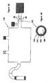
- a system 10a similar in most respects to the system 10 of FIGS. 1 and 2, with. like part numbers denoted with an "a" appended thereto, also incorporates an orifice plate 20a.
- a first pathway 40 contains a throttle valve 42 and a second pathway 44 contains a throttle valve 46 and the orifice plate 20a.
- the first throttle valve 42 is open leaving the pump 16a freely connected to the chamber 12a.
- the first throttle valve 42 is closed thereby forcing the pump 16a to evacuate through the orifice plate 20a and thus draw out of the chamber 12a at a slower, controlled rate more conducive to preferentially drawing water out of the hydrogen peroxide solution and out of the chamber 12a.
- a valve 112 comprises a valve body 114, a valve seat 116 and a valve element 118, such as a butterfly disc, plug or the like.
- An orifice 120 is provided through the valve element.
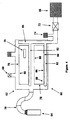
- FIG. 4 illustrates a sterilization system 60 comprising a chamber 62 having a vaporizer 64, vacuum pump 66 and vent 68 connected thereto.
- a vaporizer 64 Preferably, an elongated, temperature controlled diffusion path 70 as previously described connects the vaporizer 64 to the chamber 62.
- a throttle valve 72 and pressure gauge 74 are provided at the pump 66.
- Articles 76 to be sterilized are placed into trays or containers 78.
- Two types of packaging are commonly used in preparing articles 76 for sterilization.
- the articles 76 are placed into a tray having a plurality of openings therein, and the tray is then wrapped with a material such as CSR wrap which passes sterilizing gases and blocks contaminating microorganisms.
- a material such as CSR wrap which passes sterilizing gases and blocks contaminating microorganisms.
- An alternative package comprises a sealable container with several ports, preferably on top and bottom surfaces thereof, with each of the ports covered by a semi - permeable membrane which passes sterilizing gases and blocks admission of contaminating microorganisms.
- Such a container is described in Nichols U.S.
- Patent No. 4,704,254 incorporated herein by reference.
- the first type of packaging is typically called a "tray” and the second a “container.”
- the term “container” as used herein is meant to refer to any container, packaging or enclosure suitable for containing articles to be sterilized in a chemical vapor environment.
- the pump 66 connects to the chamber 62 via an exhaust manifold 80.
- the manifold 80 comprises one or more shelves 82 for supporting and receiving one or more containers 78 and which connect fluidly through the throttle valve 72 to the pump 66.
- An opening, or preferably a plurality of openings 84 on the upper surfaces of the shelves 82 allow the pump 66 to draw atmosphere within the chamber 62 through the openings 84, through the manifold 80 and out through the pump 66.
- the containers 78 preferably have openings 86 on a lower surface 88 thereon and additional openings 90 on at least one other surface.
- atmosphere being exhausted by the pump 66 is drawn in part through the openings 90 into the container 78, through the container into contact with the article or articles 76 therein and then out through the openings 86 into the manifold 80 through the openings 84 therein.
- the atmosphere being so exhausted contains a sterilizing gas it enhances its penetration into the containers 78 and into contact with the articles 76 therein.
- Sterilizing gases are so exhausted during the previously described cycle as the sterilant solution is vaporizing and immediately before the second admission of hydrogen peroxide.
- Such a cycle can also further provide a pump-down after some period of diffusion.
- After admitting the sterilant vapor the chamber 62 pressure rises slightly due to the presence of additional gas therein, typically from about 0.5 torr to about 10 torr. Higher pressure can also be achieved with higher load and chamber temperatures.
- FIGS. 5 and 6 an alternative design (in which like part numbers to those of the design of FIG. 4 are designated with a "b" appended thereto) replaces the manifold 80 of the design of FIG. 4 with a simple port 92.
- the port 92 is covered by a support 94 for the container 78, the support 94 having a plurality of openings 96 wherethrough so that the chamber 62b is in fluid communication with the pump 66b through the container 78, the support 94 and the port 92.
- the support 94 can be removable.
- FIGS. 7 and 8 shows a support 100 resting on a surface 102 in the chamber 62c through which penetrates the port 92c.
- the support 100 surrounds the port 92c.
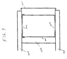
- a container 200 has one or more upper openings 202 and one or more lower openings 204.
- the container fits within a chamber 206 via a door 207,
- the chamber 206 has an inlet manifold 208 connected to the vaporizer (not shown in FIG. 9) and an outlet manifold 210 connected to the vacuum pump (not shown in FIG. 9).
- the upper and lower openings 202 and 204 are filtered in some fashion as herein described before so as to allow ingress and egress of sterilizing gases while preventing the ingress of contaminating microorganisms.
- Multiple containers 200 could be located between the inlet and outlet manifolds 208 and 210, each container 200 being individually sealed.
- FIG. 10 illustrates a further container 220 in the chamber 206, the container 220 further having a manifold 222 connected to lower openings 224 (or alternatively to upper openings 226).
- the manifold 222 is preferably designed so as to fluidly connect to a remainder 236 of the container 220 solely though the lumen 230, thus forcing flow of sterilizing gases through the lumen 230.
- a vacuum is drawn upon the container 220 and then sterilizing gases admitted thereto through the inlet manifold 208. During this step, or thereafter, some portion of the gases are exhausted through the exhaust manifold 210 to flow sterilizing gases into the lumen 230.
- a number of such lumen devices 228 can similarly connect to the manifold 222.
- the connection thereto is normally closed until the device 228 is connected thereto so as to prevent formation of a bypass route for the gases to avoid passing through the lumen 230.
- a bypass valve (not shown) could be provided between the manifold 222.and the remainder of the container 236, which valve would open only under a predetermined pressure difference.
- FIG. 11 illustrates a container 250 which can be disposed within a sterilization chamber 252 via a door 254.
- a single manifold 256 in the chamber 252 interfaces with the container 250 via an opening 258 in the manifold 256 and an opening 260 in the container 250 which are adjacent one another. No physical attachment between the container 250 and manifold 256 need occur.
- the container 250 rests atop the manifold 256 with the openings 258 and 260 in registry.
- the opening 260 could be provided in sidewalls or top walls of the container 250 with the opening 258 being moved so as to register therewith.
- the container 250 and manifold 256 would preferably merely abut one another.
- a source of sterilant 262 such as a vaporizer, connects the manifold 256 as does an exhaust pump 264, such as a vacuum pump.
- Each of the source 262 and the pump 264 can be isolated from the manifold via valves 266 and 268 respectively. While sterilant flows through the manifold 256 to the container 250, the valve 268 isolates the pump 264 from the manifold 256 and while the pump 264 is working, the valve 266 would isolate the vaporizer 262 from the manifold. Additional openings 270 could be provided in the container 250 to allow diffusion of sterilant out of the container 250 into the chamber 252.
Landscapes
- Health & Medical Sciences (AREA)
- Life Sciences & Earth Sciences (AREA)
- Surgery (AREA)
- Veterinary Medicine (AREA)
- Public Health (AREA)
- General Health & Medical Sciences (AREA)
- Animal Behavior & Ethology (AREA)
- Optics & Photonics (AREA)
- Pathology (AREA)
- Engineering & Computer Science (AREA)
- Biomedical Technology (AREA)
- Heart & Thoracic Surgery (AREA)
- Medical Informatics (AREA)
- Molecular Biology (AREA)
- Radiology & Medical Imaging (AREA)
- Physics & Mathematics (AREA)
- Nuclear Medicine, Radiotherapy & Molecular Imaging (AREA)
- Biophysics (AREA)
- Chemical & Material Sciences (AREA)
- Chemical Kinetics & Catalysis (AREA)
- General Chemical & Material Sciences (AREA)
- Epidemiology (AREA)
- Apparatus For Disinfection Or Sterilisation (AREA)
Applications Claiming Priority (4)
| Application Number | Priority Date | Filing Date | Title |
|---|---|---|---|
| US18503102A | 2002-06-28 | 2002-06-28 | |
| US185031 | 2002-06-28 | ||
| US10/324,356 US7608218B2 (en) | 2002-06-28 | 2002-12-20 | Sterilization with flow through container |
| US324356 | 2002-12-20 |
Publications (2)
| Publication Number | Publication Date |
|---|---|
| EP1378253A1 true EP1378253A1 (de) | 2004-01-07 |
| EP1378253B1 EP1378253B1 (de) | 2008-09-17 |
Family
ID=29720947
Family Applications (1)
| Application Number | Title | Priority Date | Filing Date |
|---|---|---|---|
| EP03254105A Expired - Lifetime EP1378253B1 (de) | 2002-06-28 | 2003-06-27 | Sterilisation mit durchströmbarem Behälter |
Country Status (7)
| Country | Link |
|---|---|
| US (1) | US7608218B2 (de) |
| EP (1) | EP1378253B1 (de) |
| JP (1) | JP4480961B2 (de) |
| AU (1) | AU2003205011B2 (de) |
| CA (1) | CA2433979C (de) |
| DE (1) | DE60323567D1 (de) |
| ES (1) | ES2312727T3 (de) |
Cited By (12)
| Publication number | Priority date | Publication date | Assignee | Title |
|---|---|---|---|---|
| US6818193B2 (en) | 1999-12-15 | 2004-11-16 | Plasmasol Corporation | Segmented electrode capillary discharge, non-thermal plasma apparatus and process for promoting chemical reactions |
| US6923890B2 (en) | 1999-12-15 | 2005-08-02 | Plasmasol Corporation | Chemical processing using non-thermal discharge plasma |
| US6955794B2 (en) | 1999-12-15 | 2005-10-18 | Plasmasol Corporation | Slot discharge non-thermal plasma apparatus and process for promoting chemical reaction |
| US7029636B2 (en) | 1999-12-15 | 2006-04-18 | Plasmasol Corporation | Electrode discharge, non-thermal plasma device (reactor) for the pre-treatment of combustion air |
| US7094322B1 (en) | 1999-12-15 | 2006-08-22 | Plasmasol Corporation Wall Township | Use of self-sustained atmospheric pressure plasma for the scattering and absorption of electromagnetic radiation |
| US7098420B2 (en) | 2001-07-02 | 2006-08-29 | Plasmasol Corporation | Electrode for use with atmospheric pressure plasma emitter apparatus and method for using the same |
| US7192553B2 (en) | 1999-12-15 | 2007-03-20 | Plasmasol Corporation | In situ sterilization and decontamination system using a non-thermal plasma discharge |
| EP2269660A1 (de) * | 2004-05-28 | 2011-01-05 | Ethicon, Inc. | Sterilizations-Desinfektionszyklusregelung |
| US8821807B2 (en) | 2009-12-03 | 2014-09-02 | Medivators Inc. | Container and system for decontaminating a medical device with a fog |
| US8889081B2 (en) | 2009-10-15 | 2014-11-18 | Medivators Inc. | Room fogging disinfection system |
| US9017607B2 (en) | 2011-05-27 | 2015-04-28 | Medivators Inc. | Decontamination system including environmental control using a decontaminating substance |
| EP3534971A4 (de) * | 2016-11-07 | 2020-06-24 | Medivators Inc. | Dekontaminationssystem mit zwangsluft und verfahren zur verwendung davon |
Families Citing this family (10)
| Publication number | Priority date | Publication date | Assignee | Title |
|---|---|---|---|---|
| US20150010432A1 (en) * | 2011-04-27 | 2015-01-08 | Sterilucent, Inc. | Sterilization System And Method With Compression and Expansion |
| DE102013001874A1 (de) * | 2013-02-02 | 2014-08-07 | Robert Simmoteit | Maschineneinsatz und Funktionsgitter |
| US10022189B2 (en) | 2013-12-16 | 2018-07-17 | Stryker Sustainability Solutions, Inc. | Apparatus and method for cleaning an instrument |
| EP4483908A3 (de) | 2016-11-15 | 2025-09-24 | Ideate Medical | Vorrichtung und verfahren zur sterilisation eines artikels |
| CN106500470B (zh) * | 2016-12-05 | 2022-06-10 | 中国药科大学 | 试管深度清洁干燥装置 |
| FI3600456T3 (fi) | 2017-03-27 | 2023-10-26 | Regeneron Pharma | Sterilointimenetelmä |
| EP3886946A1 (de) | 2019-06-05 | 2021-10-06 | Regeneron Pharmaceuticals, Inc. | Vorrichtungen und verfahren zur präzisionsdosisverabreichung |
| CA3221376A1 (en) | 2021-05-26 | 2022-12-01 | Ideate Medical, Inc. | Port connectors |
| CN114061266B (zh) * | 2021-07-23 | 2023-03-28 | 深圳市美雅洁技术股份有限公司 | 一种快速低温真空干燥的设备 |
| USD1120314S1 (en) | 2022-11-30 | 2026-03-24 | Regeneron Pharmaceuticals, Inc. | Dose delivery device |
Citations (4)
| Publication number | Priority date | Publication date | Assignee | Title |
|---|---|---|---|---|
| US4410492A (en) * | 1981-02-13 | 1983-10-18 | Ben Venue Laboratories, Inc. | Sterilizing method incorporating recirculation of chamber atmosphere |
| US5534221A (en) * | 1992-03-13 | 1996-07-09 | American Sterilizer Company | Device and system for sterilizing objects |
| EP0923949A2 (de) * | 1997-12-17 | 1999-06-23 | Ethicon, Inc. | Vorrichtung und Verfahren zur Zuführung von Flüssigkeiten auf Geräte mit verminderter Verstopfung oder ohne Verstopfung |
| WO2002049682A1 (en) * | 2000-12-21 | 2002-06-27 | Ethicon, Inc. | Attachable container sterilization system |
Family Cites Families (8)
| Publication number | Priority date | Publication date | Assignee | Title |
|---|---|---|---|---|
| US5202098A (en) * | 1984-11-05 | 1993-04-13 | Nichols Robert L | Medical instrument sterilization container with pressure induced positive drainage |
| US5424046A (en) * | 1992-02-28 | 1995-06-13 | Smith; Benjamin G. | Method and apparatus for steam sterilization |
| EP0583465A1 (de) | 1992-03-13 | 1994-02-23 | American Sterilizer Company | Sterilisationsvorrichtung und verfahren für mehrkomponentsterilisationsmittel |
| DE4323815C2 (de) * | 1993-07-15 | 1997-09-25 | Siemens Ag | Verfahren und Vorrichtung zur hygienischen Aufbereitung von medizinischen, insbesondere zahnmedizinischen Instrumenten |
| US5792422A (en) * | 1996-12-20 | 1998-08-11 | Ethicon, Inc. | Liquid/vapor sterilization container systems |
| US5869000A (en) | 1997-06-20 | 1999-02-09 | Johnson & Johnson Medical, Inc. | Partial vapor removal through exhaust port |
| US6365102B1 (en) * | 1999-03-31 | 2002-04-02 | Ethicon, Inc. | Method of enhanced sterilization with improved material compatibility |
| US6534000B1 (en) * | 2000-04-28 | 2003-03-18 | Steri Source, Inc. | Sterilization cassette and method |
-
2002
- 2002-12-20 US US10/324,356 patent/US7608218B2/en active Active
-
2003
- 2003-06-27 AU AU2003205011A patent/AU2003205011B2/en not_active Ceased
- 2003-06-27 DE DE60323567T patent/DE60323567D1/de not_active Expired - Lifetime
- 2003-06-27 EP EP03254105A patent/EP1378253B1/de not_active Expired - Lifetime
- 2003-06-27 ES ES03254105T patent/ES2312727T3/es not_active Expired - Lifetime
- 2003-06-27 CA CA2433979A patent/CA2433979C/en not_active Expired - Fee Related
- 2003-06-30 JP JP2003187082A patent/JP4480961B2/ja not_active Expired - Fee Related
Patent Citations (4)
| Publication number | Priority date | Publication date | Assignee | Title |
|---|---|---|---|---|
| US4410492A (en) * | 1981-02-13 | 1983-10-18 | Ben Venue Laboratories, Inc. | Sterilizing method incorporating recirculation of chamber atmosphere |
| US5534221A (en) * | 1992-03-13 | 1996-07-09 | American Sterilizer Company | Device and system for sterilizing objects |
| EP0923949A2 (de) * | 1997-12-17 | 1999-06-23 | Ethicon, Inc. | Vorrichtung und Verfahren zur Zuführung von Flüssigkeiten auf Geräte mit verminderter Verstopfung oder ohne Verstopfung |
| WO2002049682A1 (en) * | 2000-12-21 | 2002-06-27 | Ethicon, Inc. | Attachable container sterilization system |
Cited By (15)
| Publication number | Priority date | Publication date | Assignee | Title |
|---|---|---|---|---|
| US7192553B2 (en) | 1999-12-15 | 2007-03-20 | Plasmasol Corporation | In situ sterilization and decontamination system using a non-thermal plasma discharge |
| US6818193B2 (en) | 1999-12-15 | 2004-11-16 | Plasmasol Corporation | Segmented electrode capillary discharge, non-thermal plasma apparatus and process for promoting chemical reactions |
| US6955794B2 (en) | 1999-12-15 | 2005-10-18 | Plasmasol Corporation | Slot discharge non-thermal plasma apparatus and process for promoting chemical reaction |
| US7029636B2 (en) | 1999-12-15 | 2006-04-18 | Plasmasol Corporation | Electrode discharge, non-thermal plasma device (reactor) for the pre-treatment of combustion air |
| US7094322B1 (en) | 1999-12-15 | 2006-08-22 | Plasmasol Corporation Wall Township | Use of self-sustained atmospheric pressure plasma for the scattering and absorption of electromagnetic radiation |
| US6923890B2 (en) | 1999-12-15 | 2005-08-02 | Plasmasol Corporation | Chemical processing using non-thermal discharge plasma |
| US7098420B2 (en) | 2001-07-02 | 2006-08-29 | Plasmasol Corporation | Electrode for use with atmospheric pressure plasma emitter apparatus and method for using the same |
| EP2269660A1 (de) * | 2004-05-28 | 2011-01-05 | Ethicon, Inc. | Sterilizations-Desinfektionszyklusregelung |
| US8889081B2 (en) | 2009-10-15 | 2014-11-18 | Medivators Inc. | Room fogging disinfection system |
| US9511162B2 (en) | 2009-10-15 | 2016-12-06 | Mar Cor Purification, Inc. | Room fogging disinfection system and method |
| US8821807B2 (en) | 2009-12-03 | 2014-09-02 | Medivators Inc. | Container and system for decontaminating a medical device with a fog |
| US9439991B2 (en) | 2009-12-03 | 2016-09-13 | Medivators Inc. | Container and system for decontaminating a medical device with a fluid |
| US9017607B2 (en) | 2011-05-27 | 2015-04-28 | Medivators Inc. | Decontamination system including environmental control using a decontaminating substance |
| US9402929B2 (en) | 2011-05-27 | 2016-08-02 | Mar Cor Purification, Inc. | Decontamination system including environmental control using a decontaminating substance |
| EP3534971A4 (de) * | 2016-11-07 | 2020-06-24 | Medivators Inc. | Dekontaminationssystem mit zwangsluft und verfahren zur verwendung davon |
Also Published As
| Publication number | Publication date |
|---|---|
| DE60323567D1 (de) | 2008-10-30 |
| ES2312727T3 (es) | 2009-03-01 |
| CA2433979A1 (en) | 2003-12-28 |
| CA2433979C (en) | 2012-05-15 |
| AU2003205011B2 (en) | 2010-12-09 |
| JP2004130081A (ja) | 2004-04-30 |
| US7608218B2 (en) | 2009-10-27 |
| EP1378253B1 (de) | 2008-09-17 |
| JP4480961B2 (ja) | 2010-06-16 |
| AU2003205011A1 (en) | 2004-01-15 |
| US20040001776A1 (en) | 2004-01-01 |
Similar Documents
| Publication | Publication Date | Title |
|---|---|---|
| EP1378252B1 (de) | Sterilisierung mit temperaturgeregelter Diffusionsstrecke | |
| CA2433979C (en) | Sterilization with flow through container | |
| CA2522509C (en) | Sterilization system and method and orifice inlet control apparatus therefor | |
| US7252800B2 (en) | Sterilization system and method and inlet control apparatus therefor | |
| US20070172383A1 (en) | Sterilizer with restrictor | |
| US7670550B2 (en) | Rapid sterilization system | |
| US20080025869A1 (en) | Sterilization system and method with heat pump operated vaporizer/condenser | |
| EP1378251B1 (de) | Sterilisationssystem und -verfahren mit temperaturgeregelter Kondensationsoberfläche |
Legal Events
| Date | Code | Title | Description |
|---|---|---|---|
| PUAI | Public reference made under article 153(3) epc to a published international application that has entered the european phase |
Free format text: ORIGINAL CODE: 0009012 |
|
| AK | Designated contracting states |
Kind code of ref document: A1 Designated state(s): AT BE BG CH CY CZ DE DK EE ES FI FR GB GR HU IE IT LI LU MC NL PT RO SE SI SK TR |
|
| AX | Request for extension of the european patent |
Extension state: AL LT LV MK |
|
| 17P | Request for examination filed |
Effective date: 20040621 |
|
| AKX | Designation fees paid |
Designated state(s): DE ES FR GB |
|
| 17Q | First examination report despatched |
Effective date: 20041021 |
|
| 17Q | First examination report despatched |
Effective date: 20041021 |
|
| GRAP | Despatch of communication of intention to grant a patent |
Free format text: ORIGINAL CODE: EPIDOSNIGR1 |
|
| GRAS | Grant fee paid |
Free format text: ORIGINAL CODE: EPIDOSNIGR3 |
|
| GRAA | (expected) grant |
Free format text: ORIGINAL CODE: 0009210 |
|
| AK | Designated contracting states |
Kind code of ref document: B1 Designated state(s): DE ES FR GB |
|
| REG | Reference to a national code |
Ref country code: GB Ref legal event code: FG4D |
|
| REF | Corresponds to: |
Ref document number: 60323567 Country of ref document: DE Date of ref document: 20081030 Kind code of ref document: P |
|
| REG | Reference to a national code |
Ref country code: ES Ref legal event code: FG2A Ref document number: 2312727 Country of ref document: ES Kind code of ref document: T3 |
|
| PLBE | No opposition filed within time limit |
Free format text: ORIGINAL CODE: 0009261 |
|
| STAA | Information on the status of an ep patent application or granted ep patent |
Free format text: STATUS: NO OPPOSITION FILED WITHIN TIME LIMIT |
|
| 26N | No opposition filed |
Effective date: 20090618 |
|
| REG | Reference to a national code |
Ref country code: FR Ref legal event code: PLFP Year of fee payment: 14 |
|
| REG | Reference to a national code |
Ref country code: FR Ref legal event code: PLFP Year of fee payment: 15 |
|
| REG | Reference to a national code |
Ref country code: FR Ref legal event code: PLFP Year of fee payment: 16 |
|
| PGFP | Annual fee paid to national office [announced via postgrant information from national office to epo] |
Ref country code: FR Payment date: 20190510 Year of fee payment: 17 |
|
| PGFP | Annual fee paid to national office [announced via postgrant information from national office to epo] |
Ref country code: ES Payment date: 20190701 Year of fee payment: 17 Ref country code: DE Payment date: 20190627 Year of fee payment: 17 |
|
| REG | Reference to a national code |
Ref country code: GB Ref legal event code: 732E Free format text: REGISTERED BETWEEN 20200109 AND 20200115 |
|
| REG | Reference to a national code |
Ref country code: DE Ref legal event code: R119 Ref document number: 60323567 Country of ref document: DE |
|
| PG25 | Lapsed in a contracting state [announced via postgrant information from national office to epo] |
Ref country code: FR Free format text: LAPSE BECAUSE OF NON-PAYMENT OF DUE FEES Effective date: 20200630 |
|
| PG25 | Lapsed in a contracting state [announced via postgrant information from national office to epo] |
Ref country code: DE Free format text: LAPSE BECAUSE OF NON-PAYMENT OF DUE FEES Effective date: 20210101 |
|
| PGFP | Annual fee paid to national office [announced via postgrant information from national office to epo] |
Ref country code: GB Payment date: 20210628 Year of fee payment: 19 |
|
| REG | Reference to a national code |
Ref country code: ES Ref legal event code: FD2A Effective date: 20211103 |
|
| PG25 | Lapsed in a contracting state [announced via postgrant information from national office to epo] |
Ref country code: ES Free format text: LAPSE BECAUSE OF NON-PAYMENT OF DUE FEES Effective date: 20200628 |
|
| GBPC | Gb: european patent ceased through non-payment of renewal fee |
Effective date: 20220627 |
|
| PG25 | Lapsed in a contracting state [announced via postgrant information from national office to epo] |
Ref country code: GB Free format text: LAPSE BECAUSE OF NON-PAYMENT OF DUE FEES Effective date: 20220627 |