EP1378302B1 - Méthode et dispositif de fabrication des cages d'armature - Google Patents
Méthode et dispositif de fabrication des cages d'armature Download PDFInfo
- Publication number
- EP1378302B1 EP1378302B1 EP03014545A EP03014545A EP1378302B1 EP 1378302 B1 EP1378302 B1 EP 1378302B1 EP 03014545 A EP03014545 A EP 03014545A EP 03014545 A EP03014545 A EP 03014545A EP 1378302 B1 EP1378302 B1 EP 1378302B1
- Authority
- EP
- European Patent Office
- Prior art keywords
- grip
- stirrup
- stirrups
- welding
- welding means
- Prior art date
- Legal status (The legal status is an assumption and is not a legal conclusion. Google has not performed a legal analysis and makes no representation as to the accuracy of the status listed.)
- Expired - Lifetime
Links
- 238000000034 method Methods 0.000 title claims abstract description 24
- 239000002184 metal Substances 0.000 title claims abstract description 23
- 229910052751 metal Inorganic materials 0.000 title claims abstract description 23
- 239000011150 reinforced concrete Substances 0.000 title claims abstract description 18
- 238000003466 welding Methods 0.000 claims abstract description 64
- 238000004519 manufacturing process Methods 0.000 claims abstract description 10
- 230000000717 retained effect Effects 0.000 claims abstract description 6
- 238000005452 bending Methods 0.000 claims description 35
- 230000033001 locomotion Effects 0.000 claims description 18
- 238000005520 cutting process Methods 0.000 claims description 9
- 239000000463 material Substances 0.000 claims description 5
- 230000005540 biological transmission Effects 0.000 claims description 2
- 238000006243 chemical reaction Methods 0.000 claims description 2
- 230000008878 coupling Effects 0.000 abstract description 4
- 238000010168 coupling process Methods 0.000 abstract description 4
- 238000005859 coupling reaction Methods 0.000 abstract description 4
- 210000003323 beak Anatomy 0.000 description 4
- 230000027455 binding Effects 0.000 description 3
- 238000009739 binding Methods 0.000 description 3
- XEEYBQQBJWHFJM-UHFFFAOYSA-N Iron Chemical compound [Fe] XEEYBQQBJWHFJM-UHFFFAOYSA-N 0.000 description 2
- 230000015572 biosynthetic process Effects 0.000 description 2
- 230000002452 interceptive effect Effects 0.000 description 2
- 230000009467 reduction Effects 0.000 description 2
- 230000002787 reinforcement Effects 0.000 description 2
- 230000006978 adaptation Effects 0.000 description 1
- 230000008901 benefit Effects 0.000 description 1
- 230000000694 effects Effects 0.000 description 1
- 229910052742 iron Inorganic materials 0.000 description 1
- 238000005304 joining Methods 0.000 description 1
- 230000000670 limiting effect Effects 0.000 description 1
- 238000002844 melting Methods 0.000 description 1
- 230000008018 melting Effects 0.000 description 1
- 230000004048 modification Effects 0.000 description 1
- 238000012986 modification Methods 0.000 description 1
- 230000036961 partial effect Effects 0.000 description 1
- 230000008569 process Effects 0.000 description 1
- 230000000284 resting effect Effects 0.000 description 1
- 238000007790 scraping Methods 0.000 description 1
- 238000007493 shaping process Methods 0.000 description 1
- 239000002699 waste material Substances 0.000 description 1
Images




Classifications
-
- B—PERFORMING OPERATIONS; TRANSPORTING
- B21—MECHANICAL METAL-WORKING WITHOUT ESSENTIALLY REMOVING MATERIAL; PUNCHING METAL
- B21F—WORKING OR PROCESSING OF METAL WIRE
- B21F27/00—Making wire network, i.e. wire nets
- B21F27/12—Making special types or portions of network by methods or means specially adapted therefor
- B21F27/121—Making special types or portions of network by methods or means specially adapted therefor of tubular form, e.g. as reinforcements for pipes or pillars
- B21F27/125—Making special types or portions of network by methods or means specially adapted therefor of tubular form, e.g. as reinforcements for pipes or pillars by attaching individual stirrups to longitudinal wires
-
- B—PERFORMING OPERATIONS; TRANSPORTING
- B21—MECHANICAL METAL-WORKING WITHOUT ESSENTIALLY REMOVING MATERIAL; PUNCHING METAL
- B21F—WORKING OR PROCESSING OF METAL WIRE
- B21F27/00—Making wire network, i.e. wire nets
Definitions
- the present invention relates to a method and an apparatus for forming metal frames for reinforced concrete.
- the reinforcement frame of reinforced concrete pillars and beams is commonly produced by using metal frames formed by longitudinal iron rods connected by suitably spaced transverse stirrups.
- the stirrups usually form a closed path, shaped for example like a quadrilateral, with overlapping ends.
- the longitudinal rods are inserted in the profile formed by the stirrups, for example at the corners of said profile.
- the method currently most widely used entails fitting the stirrups manually over the longitudinal rods, which are grouped and rested on suitable supports. After appropriately spacing the stirrups apart, and after tracing their position manually, some of the rods are tied to the upper portion of the stirrups. In the case, for example, of the stirrups having a quadrilateral profile, two longitudinal rods are tied at the corners of the upper horizontal side of the profile.
- a considerable execution time is required in particular both by the step for positioning the stirrups and the longitudinal rods of the frame and by the step for fixing said rods to the stirrups.
- Another method in use entails shaping panels made of electrowelded mesh.
- the longitudinal rods are normally added to the structure thus formed and are fixed in the manner described above.
- electrowelded mesh reduces the expenditure of labor for tying, but has the considerable limitation of being usable only for frames that have simple shapes and requires cutting the mesh panels to size, with a considerable waste of material and time.
- European patent EP 0667195 discloses a method for forming metal frames for reinforced concrete which entails first of all the provision of an intermediate frame constituted by stirrups that have a closed profile, are arranged on suitably spaced parallel planes, and are fixed to at least two throwaway longitudinal rods, which are welded externally to the stirrups. A plurality of rods is then coupled to said lattice, and said rods are inserted within the stirrups and tied to at least some of said stirrups with known methods.
- the apparatus that provides the cited solution is of the semiautomatic type and accordingly requires the use of labor.
- the stirrups produced by the stirrup bending machine must be picked up manually by the assigned personnel and first inserted one at a time between the auxiliary rods and then pushed between the clamps of the welding elements of the machine in order to form the lattice.
- the aim of the present invention is to solve the cited problems, by providing a method and an apparatus that allow to provide complete automation in the production of metal frames for reinforced concrete.
- an object of the present invention is to provide a method that allows to provide metal frames for reinforced concrete with a considerable reduction of production times.
- Another object of the invention is to provide an apparatus that allows to automate the production of metal frames for reinforced concrete with a structure that is simple in concept, safely reliable in operation, and versatile in use.
- a method for forming metal frames for reinforced concrete characterized in that it comprises the steps of:
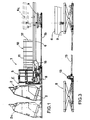
- the reference numeral 1 generally designates the apparatus for forming metal frames for reinforced concrete according to the present invention.
- the apparatus 1 is suitable to be associated with a conventional stirrup bending machine 2; conveniently, the stirrup bending machine 2 is mounted on a truck 3 that can move on a portion of track 4 that is arranged in series to the apparatus 1.
- stirrup bending machine 2 has a working surface that is arranged vertically for the sake of convenience.
- the apparatus 1 has a chassis 5 that is provided with the working elements of the apparatus and is arranged in front of the stirrup bending machine 2.
- a longitudinally elongated platform 6 protrudes from the chassis 5 and forms a horizontal working surface.
- An intermediate lattice 10 for the final forming of a frame is meant to form on the working surface of the platform 6 and is obtained, as specified hereinafter, by joining longitudinal auxiliary rods 11 externally to a series of stirrups 12.
- the auxiliary rods 11 unwind from corresponding spools 7 which are arranged, preferably with a vertical axis, at the sides of the platform 6.
- the platform 6 has a first input portion 16 that is suitable to be connected to the chassis 5; the first portion 16 of the platform 6 is conveniently provided with two longitudinal slots 17 that are suitable to allow the passage of the movable supports 77, which rigidly follow the longitudinal movement of the clamps (see Figures 7 and 10).
- the chassis 5 and the platform 6 are adjustable in a vertical direction monolithically with each other, depending on the dimensions of the stirrups 12 being worked.
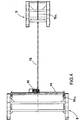
- the chassis 5 and the platform are supported by pantograph-type lifting elements 8 and 9, which are actuated synchronously by means of a motor 13 that turns suitable screw elements 14, 14a and 15, 15a (see in particular Figures 3 and 4).
- the chassis 5 is constituted by two lateral cross-members 18, which are connected at the base by two transverse longitudinal members 19.
- the cross-members 18 are suitable to be fixed, by means of screw elements, to corresponding lateral portions of the first lifting element 8, whose width is proportionate to the width of the chassis 5.
- Respective rail-type guides 20 are associated with the longitudinal members 19, and a plurality of trucks 21 and 22 can slide thereon; said trucks are mounted on wheels 23 and can be moved manually transversely to the line for forming the lattice 10. More precisely, the apparatus has two lateral trucks 21, which are mutually symmetrical, and a central truck 22.
- the trucks 21, 22 are constituted by respective frames, each mounted on three wheels 23 per side, arranged with suitably offset axes 24, which slide within the rails 20.
- the trucks 21 and 22 are further provided so that they can be blocked in the working position by way of respective braking elements 25 that are actuated pneumatically.
- the trucks 21 and 22 support respective working heads 31 and 32 that are meant to weld the auxiliary rods 11 to the stirrups 12 and to draw the lattice 10 being formed.
- the auxiliary rods 11 that unwind from the spools 7 are diverted on rollers 26, which are mounted so that they can rotate on vertical rods 27 that are fixed at the cross-members 18 of the chassis 5, and said rods then engage respective straightening elements 28 that are moved into position by the trucks 21 and 22 and are constituted by a series of rollers that have a vertical axis.
- Corresponding portal-shaped frameworks 30 rise from the lateral trucks 21, and the lateral working heads 31 can move thereon in a vertical direction.
- the lateral working heads 31 are mounted respectively on a cross-member 34, which is provided at its ends with sliders 35 that can slide on vertical guides 36 formed by the posts 37 of the portal-shaped framework 30.
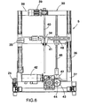
- the upper cross-member 38 of the portal-shaped framework 30 supports a motor element 39, which actuates a threaded shaft 40, that is rotatable about a vertical axis and is arranged so as to engage a female thread element 41 that is associated with the cross-member 34 ( Figure 6).
- the lateral working heads 31 can be moved in a transverse direction by way of the movement of the corresponding trucks 21 and that the height of their position can be adjusted independently by way of the corresponding motor elements 39; the lateral working heads 31, moreover, can be rotated angularly at respective pivots 29.
- the central working head 32 is instead fixed on the corresponding truck 22, and therefore its position can be adjusted only in a transverse direction.
- the height of the central working head 32 is actually adjusted by way of the pantograph-type lifting elements 8 and 9, which move the chassis 5 and the platform 6 in a vertical direction, depending on the dimensions of the stirrups 12 being worked.
- stirrups 12 have a fixed reference position on the apparatus, defined in practice by the cutting elements 90 of the stirrup bending machine 2, at the upper arm of the stirrups 12, while the position of the lower arm is determined accordingly by the dimensions of the stirrups 12 and is obtained through the adjustment of the height of the chassis 5 and of the platform 6 by virtue of the pantograph-type lifting elements 8 and 9.
- the pantograph-like lifting elements 8 and 9 are adapted to move the chassis 5 and the platform 6 to a maximum lifting position, shown schematically by the dashed line 6a in Figure 1, which in practice coincides with said fixed reference position defined by the cutting elements 90 of the stirrup bending machine 2.
- the apparatus actually allows to work stirrups constituted by linear bar segments, in order to provide with the longitudinal auxiliary rods 11 a mesh-like lattice or stirrups formed toward the upper part of the machine, i.e., with the reference of the zero plane in the lower part of the stirrup instead of in the upper region.
- the central truck 22 in turn supports a gearmotor 42, which is suitable to actuate, by way of a suitable gear 43, a transverse splined shaft 44, which is supported so that it can rotate about a horizontal axis between the cross-members 18 of the chassis 5.
- the horizontal splined shaft 44 is provided so as to transmit motion, by way of a corresponding bevel gear pair 45, to respective vertical shafts 46, which are supported rotatably by the lateral trucks 21 at a box 47; the vertical shafts 46 turn a gear 48, which is meant to actuate, as specified hereinafter, traction means that are associated with said lateral working heads 31.
- An additional gear 49 is furthermore mounted on the horizontal splined shaft 44 and is meant to actuate, in turn, traction means that are associated with the central working head 32.
- the position of the working heads 31 and 32 is adjusted by first moving said working heads 31 and 32 simultaneously in a vertical direction; once the correct position intended for the central working head 32 is reached, the lateral working heads 31 provided with individual adjustment movements are adjusted with respect to said central working head.
- Each one of the working heads 31 and 32 is provided with respective means 50 for gripping and welding the auxiliary rods 11 and the stirrups 12 that are designed to form said intermediate lattice 10.
- said grip and welding means 50 have a grip element 51, which is constituted by a beak 52 that is rigidly coupled to the stem 53 of a linear actuator 54 ( Figure 13).
- the actuator 54 is fixed to a bracket 55 that is rigidly coupled to a stem 56 that is guided so that it can slide, in contrast with elastic means 57, through a sliding block 58, which is in turn rigidly coupled to the stem 60 of a second linear actuator 61, along an axis that is parallel to the axis of the first actuator 54.
- the second actuator 61 is supported by a brace 63, which is provided with a pair of stems 64 for guiding the sliding block 58.
- the bracket 55 is provided with a housing 65 for protecting the beak 52.
- the bracket 55 is furthermore provided with a protruding roller 59, which is suitable to act as a locator on the front surface of the stirrup bending machine 2.
- the brace 63 is fixed to the end of a pair of horizontal guiding shafts 66, which pass slidingly through a body 67. At the opposite end, the shafts 66 are fixed by means of a plate 68 to the stem 69 of a double-stroke actuator 70, which in practice is constituted by a first long-stroke jack 71 and by a second short-stroke jack 72, which are arranged in series.
- the body 67 is fixed, by means of a flange 73, to a box-like enclosure 74, which acts as a support for a transformer element 75.
- the enclosure 74 has a rack 76 rigidly coupled below it; said rack is suitable to mesh with a corresponding gear 48 and 49, which is turned by the gearmotor 42 by means of the splined shaft 44.
- the illustrated case which relates to the central working head 32, shows the coupling of the rack 76 to the gear 49 mounted at the central truck 22.
- welding means 80 which are supported in a cantilevered fashion and are constituted by movable welding units 81, which cooperate with fixed welding units 82 (see in particular Figures 22 and 23).
- the movable welding units 81 are supported by an arm 83, which can be actuated by a linear actuator 84.
- the fixed welding units 82 are mounted on a body 85, which is supported elastically on stems 86 in contrast with elastic means 87.
- the method for forming metal frames for reinforced concrete by means of the described apparatus mainly entails forming a lattice 10 that is constituted by a plurality of stirrups 12 that have a closed or open profile, are arranged on suitably spaced parallel planes, and are mutually connected by one or more longitudinal auxiliary rods 11 welded to the outside of said stirrups 12.
- the stirrups 12 form a substantially rectangular profile and are mutually connected by means of three auxiliary rods 11, which are arranged respectively on the lateral portions and on the lower portion of the stirrups 12 (see Figure 9).
- the stirrups 12 can of course have any kind of shape, even a very complex one.
- the auxiliary rods 11 are constituted by rods that have any cross-section, for example a narrow one, which is not defined by the designer of the structure. Preferably, the auxiliary rods 11 are thinner than the stirrups. Clearly, in addition to having a circular cross-section, the auxiliary rods 11 can also have a flattened shape or other similar shapes. It is further possible to provide on the auxiliary rods 11 suitable shaped portions or distinctive elements of any kind, for example a series of suitably spaced recesses.
- auxiliary rods 11 that unwind from the spools 7 engage respectively the straightening elements 28, which are carried in an adjustable position by the trucks 21 and 22 of the apparatus, and are then welded by the corresponding working heads 31 and 32 to the stirrups 12 provided by the stirrup bending machine 2.
- the stirrups 12 are picked up automatically on the stirrup bending machine 2, which for this purpose is arranged, so that its working surface is preferably vertical, in front of the described apparatus, at an input region E thereof ( Figure 1).
- the apparatus grips the stirrup 12 to be picked up by means of the grip elements 51 of the working heads 31 and 32 before the cutting of said stirrup 12 from the material in bar or coil form from which it is obtained by bending.
- the grip elements 51 are moved by the double-stroke actuator 70 into a grip position that is formed by the abutment of the roller 59 on the stirrup bending machine 2, with the beak 52 open on a corresponding portion of the stirrup 12 ( Figure 14).
- stirrup 12 After the stirrup 12 has been gripped by the grip elements 51, said stirrup 12 is cut by the conventional cutting elements 90 of the stirrup bending machine 2 ( Figure 5).
- the stirrup 12 gripped by the grip elements 51 is then moved in a longitudinal direction by virtue of the actuation of the corresponding double-stroke actuators 70, until a preset working position (Figure 16) is reached.
- the welding means 80 preset in said working position, are activated.
- the movable welding units 81 are lifted by the actuator 84 ( Figure 17), followed by a suitable retraction stroke of the grip elements 51 under the control of the second short-stroke jack 72 of the actuator 70, in order to place the stirrup 12 at said movable welding units 81 ( Figure 18).
- This is followed by the fastening of said stirrup 12 between the welding units 81 and 82, for example of the resistance type, and by the release of the stirrup 12 on the part of the grip elements 51, in order to weld externally to said stirrup the auxiliary rod 11 simultaneously fed in a longitudinal direction (Figure 19).
- stirrups 12 is welded at the chosen distance to the auxiliary rods 11 so as to form the lattice 10.
- the mutual distance between the stirrups 12 is not necessarily constant, but can be changed along the longitudinal extension of the lattice 10, according to the various requirements.
- auxiliary rods 11 are preferably narrower than the stirrups 12, said stirrups are not affected by the welding step that instead causes the local melting only of the auxiliary rods 11.
- the resulting lattice 10 can be used to provide the metallic frame, in particular by coupling suitable rods 12 inside the stirrups 12. More specifically, the rods used to form the frames are constituted by longitudinal supporting bars, whose characteristics are determined by the designer of the structure according to calculations in accordance with the applicable standards. The supporting bars are fixed to at least some of the stirrups 12 of the lattice 10, for example by means of conventional bindings.
- stirrups 12 are instead already fixed and spaced by virtue of the welding with the auxiliary rods 11 of the lattice 10 and therefore bindings are needed only to keep the longitudinal bars in position.
- the method and the apparatus according to the invention allow to provide complete automation in the production of intermediate lattices for forming metal frames for reinforced concrete, eliminating the need for the operator to pick up the stirrups from the stirrup bending machine, carry them and insert them manually and individually in the assembly apparatus by means of a second operator.
- the apparatus according to the invention is free at the front input region E, so that the stirrups 12 can be picked up at the front.
- the apparatus can therefore adapt to any kind of stirrup bending machine without requiring structural modifications.
- the straightening elements 28 supported by the trucks 21 and 22 are arranged in an oblique position that converges toward the output with respect to the lattice 10 being formed, so as to form, with the corresponding auxiliary rods 11, a sort of funnel.
- This allows to have enough free space to introduce the stirrup 12 at the front, without interfering with said straightening units 28 and without the risk of any scraping of the stirrup 12 against the rods 11.
- the auxiliary rods 11 in fact assume a path that is substantially tangent to the lattice 10 only after they have been welded.
- stirrups 12 are loaded manually or by way of automatic loading means of a different type, for particular production requirements.
- One prerogative of the method and apparatus according to the invention is constituted by the fact that the advancement of the lattice 10 being formed is provided by the welding elements 80 that weld the stirrups 12 to the auxiliary rods 11. It is therefore possible to weld the stirrups 12, at least partially, during said step for the advancement of the lattice 10, with an overlap of the two steps that obviously leads to a substantial reduction in downtimes and therefore to a significant time saving.
- auxiliary rods 11 can be joined to the stirrups 12 through any type of coupling, particularly through any welding method.
- the rods 11 can be located on any side of the stirrups 12, and there may be even more than one rod per side, according to the requirements.
- the method for moving the frame being formed may also be any, by traction or pushing, for example by using traction wheels integrated in the straightening unit.
- the materials used may be any according to requirements.
Landscapes
- Engineering & Computer Science (AREA)
- Mechanical Engineering (AREA)
- Wire Processing (AREA)
- Reinforcement Elements For Buildings (AREA)
- Rod-Shaped Construction Members (AREA)
- Bulkheads Adapted To Foundation Construction (AREA)
- Working Measures On Existing Buildindgs (AREA)
Claims (26)
- Procédé de formation d'ossatures métalliques pour du béton armé, caractérisé en ce qu'il comprend les étapes suivantes :(a) arrêter le cycle de travail d'un appareil de cintrage d'étriers (2) avant de découper des étriers individuels (12) ayant un profil fermé ou ouvert, de telle sorte que lesdits étriers individuels (12) sont agencés sur une surface de travail dudit appareil de cintrage d'étriers (2) qui fait face à une région d'entrée avant (E) d'un appareil (1) pour former les ossatures métalliques, qui est agencé en aval dudit appareil de cintrage d'étriers (2) ;(b) saisir à la suite un unique étrier (12) agencé sur ledit appareil de cintrage d'étriers à l'aide de moyens de préhension et de soudage (50) qui peuvent se déplacer le long d'une direction longitudinale par rapport à ladite région d'entrée (E) ;(c) découper ledit étrier (12) saisi par lesdits moyens de préhension et de soudage (50) au niveau dudit appareil de cintrage d'étriers (2) à partir dudit matériau source ;(d) fixer de manière externe à chaque étrier (12), retenu par lesdits moyens de préhension et de soudage (50), au moins une tige auxiliaire (11) longitudinale ;(e) réaliser, avec une synchronisation appropriée, le mouvement alterné desdits moyens de préhension et de soudage (50) dans une position avant, en actionnant les moyens de traction (74) qui peuvent se déplacer le long de ladite direction longitudinale, afin de produire la traction par palier de ladite tige auxiliaire (11) et desdits étriers (12), pendant le soudage de ceux-ci réalisé par les moyens de soudage (80) qui sont associés auxdits moyens de préhension et de soudage (50), de manière à former un lattis intermédiaire (10) pour la production finale d'une ossature.
- Procédé de formation d'ossatures métalliques pour du béton armé, caractérisé en ce qu'il comprend les étapes suivantes :(a) agencer à la suite des étriers individuels (12) ayant un profil fermé ou ouvert au niveau d'une région d'entrée avant (E) d'un appareil permettant de former des ossatures métalliques ;(b) saisir un unique étrier (12) à partir de ladite région d'entrée avant (E) à l'aide de moyens de préhension et de soudage (50) qui peuvent se déplacer le long d'une direction qui est longitudinale par rapport à ladite région d'entrée (E) ;(c) fixer de manière externe à chaque étrier (12), retenu par lesdits moyens de préhension et de soudage (50), au moins une tige auxiliaire (11) longitudinale ;(d) réaliser, avec une synchronisation appropriée, le mouvement alterné desdits moyens de préhension et de soudage (50) dans une position avant, par l'actionnement des moyens de traction (74), afin de produire la traction par palier de ladite tige auxiliaire (11) et desdits étriers (12), pendant le soudage de ceux-ci réalisé par des moyens de soudage (80) qui sont associés auxdits moyens de préhension et de soudage (50), de manière à former un lattis intermédiaire (10) pour la production finale d'une ossature.
- Procédé selon la revendication 2, caractérisé en ce que ladite étape de :(b) saisie d'un unique étrier (12) à partir de ladite région d'entrée avant (E) comporte la saisie dudit étrier (12) à l'aide de moyens de préhension (51) qui sont associés auxdits moyens de préhension et de soudage (50) et le transfert dudit étrier (12) vers lesdits moyens de soudage (80), qui sont associés auxdits moyens de traction (74).
- Procédé selon la revendication 3, caractérisé en ce qu'il comporte la réalisation simultanément du déplacement desdits moyens de soudage (80) vers ladite position avant par l'actionnement desdits moyens de traction (74), pour faire avancer par palier ledit lattis intermédiaire(10), et de la course de retour dans le sens opposé desdits moyens de préhension (51) au niveau de ladite région d'entrée avant (E), en actionnant les moyens d'actionnement (70) correspondants afin de saisir un étrier (12) suivant.
- Procédé selon la revendication 2, caractérisé en ce que ladite étape consistant à :(d) produire le mouvement alterné desdits moyens de préhension et de soudage (50) dans une position avant par l'actionnement desdits moyens de traction (74) ;
comporte(d1) le fait que lesdits moyens de traction (74) sont amenés à effectuer une course de retour, après la libération de ladite tige auxiliaire (11) et dudit étrier (12) sur la partie desdits moyens de préhension et de soudage (50) dans ladite position avant. - Procédé selon la revendication 2, caractérisé en ce qu'il comprend les étapes supplémentaires :(e) insérer une série de barres de support longitudinales à l'intérieur dudit lattis (10) ; et(f) fixer lesdites barres de support sur certains desdits étriers (12) par soudage ou attache.
- Appareil permettant de former des ossatures métalliques en béton armé, caractérisé en ce qu'il comprend : une région d'entrée avant (E), dans laquelle des étriers (12) individuels ayant un profil fermé ou ouvert peuvent être délivrés à la suite ; des moyens de préhension et de soudage (50), qui peuvent se déplacer dans une direction longitudinale par rapport à ladite région d'entrée (E) et qui sont adaptés pour saisir un unique étrier (12) à partir de ladite région d'entrée avant (E) et fixer de manière externe à celui-ci au moins une tige auxiliaire (11) longitudinale ; des moyens de traction (74), qui sont associés auxdits moyens de préhension et de soudage (50) et peuvent se déplacer de manière alternée le long de ladite direction longitudinale afin de produire la traction par palier de ladite tige auxiliaire (11) externe et desdits étriers (12), retenus par lesdits moyens de préhension et de soudage (50), afin de former un lattis intermédiaire (10) pour la formation finale d'une ossature.
- Appareil selon la revendication 7, caractérisé en ce que lesdits moyens de préhension et de soudage (50) peuvent se déplacer le long d'une direction longitudinale qui est sensiblement perpendiculaire à un plan vertical tracé par ladite région d'entrée avant (E).
- Appareil selon la revendication 7, caractérisé en ce que ladite tige auxiliaire (11) se déroule à partir d'une bobine (7) qui est agencée sur le côté d'une plate-forme (6) sur laquelle est formé ledit lattis intermédiaire (10).
- Appareil selon la revendication 9, caractérisé en ce que ladite tige auxiliaire (11) qui se déroule à partir de ladite bobine (7) est adaptée pour venir en prise avec des moyens raidisseurs (28), qui sont agencés dans une position oblique et convergente du côté de la sortie par rapport à l'axe le long duquel ledit lattis intermédiaire (10) est formé, de manière à libérer le passage afin de saisir lesdits étriers (12).
- Appareil selon la revendication 7, caractérisé en ce que lesdits moyens de préhension et de soudage (50) sont supportés par des têtes fonctionnelles (31, 32) dont la position peut être réglée sur un châssis (5) agencé devant ladite région d'entrée (E).
- Appareil selon la revendication 11, caractérisé en ce que lesdites têtes fonctionnelles (31, 32) sont ajustables en fonction des dimensions desdits étriers (12) à saisir, suite à un mouvement simultané dans une direction verticale effectué par ledit châssis (5), qui est supporté par des éléments de levage (8) appropriés, jusqu'à ce que la position correcte pour une tête fonctionnelle de référence (32) soit atteinte, ladite tête fonctionnelle de référence étant de préférence agencée au niveau d'une partie inférieure desdits étriers (12) à saisir, et au mouvement suivant des têtes fonctionnelles (31) supplémentaires, qui ont des mouvements d'ajustement individuels par rapport à ladite tête fonctionnelle de référence (32).
- Appareil selon la revendication 11, caractérisé en ce que lesdites têtes fonctionnelles (31, 32) sont supportées par des chariots (21, 22) respectifs, qui peuvent se déplacer sur ledit châssis (5), à l'aide de guides coulissants (20), le long d'une direction qui est transversale à ladite direction longitudinale de déplacement desdits moyens de traction (74).
- Appareil selon la revendication 13, caractérisé en ce qu'il comporte deux têtes fonctionnelles (31) latérales, qui peuvent se déplacer dans une direction verticale sur une charpente (30) qui s'élève à partir des chariots latéraux (21) respectifs.
- Appareil selon la revendication 14, caractérisé en ce que lesdites têtes fonctionnelles latérales (31) sont montées respectivement sur un élément transversal (34) qui est doté, au niveau de ses extrémités, de coulisseaux (35) qui peuvent coulisser sur des guides verticaux (36), formés par des montants (37) de ladite charpente (30) et peuvent se déplacer en étant commandés par un élément moteur (39), qui est supporté par ladite charpente (30) et est approprié pour actionner un arbre fileté (40) qui peut tourner autour d'un axe vertical et est approprié pour venir en prise avec un élément fileté femelle (41) associé audit élément transversal (34).
- Appareil selon la revendication 13, caractérisé en ce qu'il comporte une tête fonctionnelle centrale (32) qui est supportée à l'aide d'un chariot central (22) respectif au niveau de la base dudit châssis (5).
- Appareil selon la revendication 7, caractérisé en ce que lesdits moyens de préhension et de soudage (50) comprennent des moyens de préhension (51), qui sont constitués par une pince (52) conçue pour être actionnée par un actionneur linéaire (54) venant en butée contre un support (55), qui est couplé fermement à une tige de commande (56) qui est guidée de telle sorte qu'elle peut coulisser, par rapport aux moyens élastiques (57), au travers d'un bloc coulissant (58) supporté devant une tête fonctionnelle (31, 32).
- Appareil selon la revendication 17, caractérisé en ce que le support flottant dudit actionneur (54) fourni en raison de ladite tige de commande (56), qui peut coulisser, par rapport auxdits moyens élastiques (57), est approprié pour produire, par réaction, le mouvement dudit support (55), permettant de centrer automatiquement ledit étrier (12) sur lesdits moyens de préhension (51).
- Appareil selon la revendication 17, caractérisé en ce que ledit bloc coulissant (58) est couplé fermement à la tige de commande (60) d'un deuxième actionneur linéaire (61), qui est approprié pour déplacer lesdits moyens de préhension (51) dans une position de dégagement abaissée.
- Appareil selon la revendication 19, caractérisé en ce que ledit deuxième actionneur linéaire (61) est couplé fermement à des tiges de commande horizontales (66), qui passent par coulissement au travers d'un corps (67) couplé fermement auxdits moyens de traction (74) et sont appropriées pour être actionnées par un actionneur (70).
- Appareil selon la revendication 7, caractérisé en ce que lesdits moyens de préhension et de soudage (50) comprennent des moyens de soudage (80) constitués par des unités de soudage mobiles (81), qui sont supportées par un bras (83) approprié pour être actionné par un actionneur linéaire (84), et qui coopèrent avec des unités de soudage fixes (82), qui sont montées sur un corps (85) supporté devant lesdits moyens de traction (74).
- Appareil selon la revendication 7, caractérisé en ce que lesdits moyens de traction (74) sont constitués par une enceinte qui est guidée de telle sorte qu'elle peut coulisser le long de ladite direction longitudinale et est dotée de manière monolithique d'une crémaillère longitudinale (76) qui est couplée à un engrenage correspondant (48, 49), qui est actionné par un moteur à engrenages (42) à l'aide d'arbres de transmission (44, 46).
- Appareil selon la revendication 11, caractérisé en ce qu'une plate-forme longitudinale (6) sur laquelle est formé ledit lattis (10) fait saillie par rapport audit châssis (5), ledit châssis (5) et ladite plate-forme (6) étant mobiles dans une direction verticale, selon les dimensions desdits étriers (12) qui sont traités, sous l'effet d'éléments de levage (8, 9) du type pantographe, qui sont actionnés de manière synchrone à l'aide d'un élément moteur (13) qui actionne les éléments de vis (14, 15) appropriés.
- Appareil selon la revendication 23, caractérisé en ce que ladite plate-forme (6) peut se déplacer dans une direction horizontale, qui est transversale à l'axe le long duquel est formé ledit lattis intermédiaire (10), et est raccordée fermement à un chariot (22) qui peut se déplacer sur ledit châssis (5) et est dotée d'une tête fonctionnelle (32) respective, en fonction de la géométrie desdits étriers (12) traités, essentiellement pour centrer la position de la base dudit lattis (10).
- Appareil permettant de former des ossatures métalliques pour du béton armé, caractérisé en ce qu'il comprend une région d'entrée avant (E), qui est adaptée pour faire face à un appareil de cintrage d'étriers (2), dans lequel il est possible d'agencer à la suite des étriers individuels (12) qui ont un profil fermé ou ouvert ; des moyens de préhension et de soudage (50), qui peuvent se déplacer le long d'une direction longitudinale par rapport à ladite région d'entrée avant (E) et sont adaptés pour saisir un unique étrier (12) sur ledit appareil de cintrage d'étriers (2) au niveau de ladite région d'entrée (E) et fixer de façon externe à celui-ci au moins une tige auxiliaire (11) longitudinale ; des moyens de traction (74), qui sont associés auxdits moyens de préhension et de soudage (50) et peuvent se déplacer de manière alternée le long de ladite direction longitudinale afin de produire la traction par palier de ladite tige auxiliaire (11) et desdits étriers (12), retenus par lesdits moyens de préhension et de soudage (50), afin de former un lattis intermédiaire (10) pour le formage final d'une ossature.
- Ensemble d'un appareil selon la revendication 25 et d'un appareil de cintrage d'étriers (2), caractérisé en ce que ledit appareil de pliage d'étrier (2) est adapté pour effectuer un mouvement relatif en s'éloignant de ladite région d'entrée avant (E) afin de permettre l'alimentation manuelle desdits étriers (12) dans ladite région d'entrée (E).
Applications Claiming Priority (2)
| Application Number | Priority Date | Filing Date | Title |
|---|---|---|---|
| IT2002BO000438A ITBO20020438A1 (it) | 2002-07-05 | 2002-07-05 | Metodo e apparecchiatura per realizzare gabbie metalliche per cementoarmato |
| ITBO20020438 | 2002-07-05 |
Publications (3)
| Publication Number | Publication Date |
|---|---|
| EP1378302A2 EP1378302A2 (fr) | 2004-01-07 |
| EP1378302A3 EP1378302A3 (fr) | 2004-09-15 |
| EP1378302B1 true EP1378302B1 (fr) | 2006-06-07 |
Family
ID=11440283
Family Applications (1)
| Application Number | Title | Priority Date | Filing Date |
|---|---|---|---|
| EP03014545A Expired - Lifetime EP1378302B1 (fr) | 2002-07-05 | 2003-07-04 | Méthode et dispositif de fabrication des cages d'armature |
Country Status (4)
| Country | Link |
|---|---|
| EP (1) | EP1378302B1 (fr) |
| AT (1) | ATE328685T1 (fr) |
| DE (1) | DE60305800D1 (fr) |
| IT (1) | ITBO20020438A1 (fr) |
Families Citing this family (19)
| Publication number | Priority date | Publication date | Assignee | Title |
|---|---|---|---|---|
| DK1570929T3 (da) * | 2004-03-05 | 2007-01-22 | Galanos S A | Automatisk montageanlæg til betonarmering |
| GR1005123B (el) * | 2004-11-03 | 2006-02-02 | Μηχανημα συναρμολογησης οπλισμου ενισχυσης σκυροδεματος | |
| DE102006004394B4 (de) | 2005-02-16 | 2011-01-13 | Kabushiki Kaisha Kobe Seiko Sho (Kobe Steel, Ltd.), Kobe-shi | Hartfilm, Mehrschichthartfilm und Herstellungsverfahren dafür |
| EP1714716A1 (fr) * | 2005-04-20 | 2006-10-25 | Galanos S.A. | Dispositif d'alimentation pour machine pour la fabrication des cages de renforcement |
| ES2264640B1 (es) * | 2005-06-17 | 2007-12-01 | Ferraplana, S.L. | Equipo automatico para la fabricacion de armaduras metalicas. |
| ITUD20060146A1 (it) * | 2006-06-08 | 2007-12-09 | Piegatrici Macch Elettr | Macchina e procedimento per la realizzazione di gabbie di armatura |
| EP1911909A1 (fr) * | 2006-10-11 | 2008-04-16 | Gravita Maquinas, S.L. | Dispositif de fabrication de cadres d'armatures |
| ES2303801B1 (es) * | 2008-02-07 | 2009-12-03 | Mecanica Riells S.L. | Procedimiento de soldadura de la armadura de un elemento estructural de hormigon armado y dispositivo de soldadura y maquina correspondient e. |
| GR1009295B (el) * | 2017-01-23 | 2018-05-23 | Αντωνιος Παναγιωτη Αναγνωστοπουλος | Συστημα εξολκευσης συρματος ή μπετοβεργας απο ευθυγραμμιστικο μηχανημα |
| CN108580758B (zh) * | 2018-06-04 | 2024-09-24 | 中国水利水电第五工程局有限公司 | 一种双层钢筋网片加工装置 |
| CN109676301A (zh) * | 2019-02-27 | 2019-04-26 | 湖北科技学院 | 一种钢筋网片自动加工平台 |
| CN111842710B (zh) * | 2020-07-31 | 2022-05-17 | 中冶建工集团有限公司 | 弯焊一体机的箍筋前夹持机构 |
| CN113828712B (zh) * | 2021-11-10 | 2023-04-11 | 河南省鼎鼎实业有限公司 | 一种带钢筋展卷功能的网焊机纵向钢筋布筋机构 |
| CN113828975B (zh) * | 2021-11-17 | 2023-12-12 | 中国建筑土木建设有限公司 | 箱梁底腹板箍筋自动化组合焊接装置及方法 |
| CN114030818B (zh) * | 2021-11-30 | 2025-06-13 | 广州容联建筑科技有限公司 | 一种柔性的钢筋笼牵引机器 |
| CN114798990B (zh) * | 2022-05-07 | 2024-02-06 | 中国核工业电机运行技术开发有限公司 | 一种纵筋上料组件 |
| CN117753895B (zh) * | 2024-02-22 | 2024-05-10 | 长子县金鑫机械电杆有限公司 | 一种混凝土电杆钢筋滚焊分段制造装备 |
| WO2026033574A1 (fr) | 2024-08-09 | 2026-02-12 | Schnell S.P.A. | Procédé et appareil de fabrication de pré-cages pour renforcement |
| CN119426901B (zh) * | 2025-01-08 | 2025-04-08 | 保利长大工程有限公司 | 一种钢筋焊接夹具 |
Family Cites Families (3)
| Publication number | Priority date | Publication date | Assignee | Title |
|---|---|---|---|---|
| WO1985005053A1 (fr) * | 1984-04-30 | 1985-11-21 | Howard Bruce | Appareil de fabrication d'etriers de renforcement de beton et leur soudage avec des tiges pour former une cage de renforcement de beton |
| IT1273800B (it) * | 1994-02-10 | 1997-07-10 | Schnell Srl | Metodo e apparecchiatura per realizzare gabbie metalliche per cemento armato e gabbia metallica cosi' ottenuta |
| IT1285930B1 (it) * | 1996-06-07 | 1998-06-26 | Schnell Spa | Apparecchiatura per realizzare gabbie metalliche per cemento armato |
-
2002
- 2002-07-05 IT IT2002BO000438A patent/ITBO20020438A1/it unknown
-
2003
- 2003-07-04 AT AT03014545T patent/ATE328685T1/de not_active IP Right Cessation
- 2003-07-04 EP EP03014545A patent/EP1378302B1/fr not_active Expired - Lifetime
- 2003-07-04 DE DE60305800T patent/DE60305800D1/de not_active Expired - Lifetime
Also Published As
| Publication number | Publication date |
|---|---|
| ATE328685T1 (de) | 2006-06-15 |
| EP1378302A2 (fr) | 2004-01-07 |
| DE60305800D1 (de) | 2006-07-20 |
| ITBO20020438A0 (it) | 2002-07-05 |
| EP1378302A3 (fr) | 2004-09-15 |
| ITBO20020438A1 (it) | 2004-01-05 |
Similar Documents
| Publication | Publication Date | Title |
|---|---|---|
| EP1378302B1 (fr) | Méthode et dispositif de fabrication des cages d'armature | |
| EP0667195B1 (fr) | Procédé et dispositif pour la fabrication de cadres métalliques pour béton armé et cadre métallique ainsi formé | |
| EP0933161B1 (fr) | Appareillage de soudage par points d'éléments de carrosserie de véhicules | |
| EP1837092B1 (fr) | Appareil automatique pour plier et insérer des barres d'armature dans des cages d'armature metalliques préformées | |
| EP0791416A1 (fr) | Procédé et dispositif pour la fabrication de cages métalliques pour béton armé | |
| DK2726230T3 (en) | METHOD AND APPARATUS FOR CONTINUOUS PREPARATION OF A GRID BEARER | |
| US3857271A (en) | Bending machine for rod or strip material | |
| US4708573A (en) | Apparatus for the handling of metal sheets | |
| US5415209A (en) | Feeder device for machines for manufacturing electrically welded metallic nets | |
| EP0648577A1 (fr) | Appareil pour le faconnage de barres en particulier des barres pour beton armé | |
| NZ211819A (en) | Assembling three-dimensional wire mesh structures from plane wire nettings | |
| US2814343A (en) | Strip splicer | |
| CN220718167U (zh) | 一种钢筋网片焊接生产设备 | |
| KR20110128879A (ko) | 평탄화 요소를 턴오버하기 위한 장치, 및 상기 장치와 결합된 평탄화 요소 | |
| EP1270110A2 (fr) | Procédé et dispositif pour la fabrication de cadres métalliques pour béton armé et cadre métallique ainsi formé | |
| EP1378301B1 (fr) | Méthode et dispositif pour la fabrication des paquets des étriers de renfort et paquet fabriqué | |
| EP1349684B1 (fr) | Dispositif pour realiser des cages d'armature et procede associe | |
| US20120193032A1 (en) | Installation and process for making panels | |
| US4141211A (en) | Traversing device in a chain manufacturing plant | |
| EP1247594B1 (fr) | Procédé de pliage de barres profilées et dispositif pour la réalisation dudit procédé | |
| EP1247595B1 (fr) | Procédé de pliage de barres profilées et dispositif pour la réalisation dudit procédé | |
| AT396943B (de) | Härtemaschine für blattfedern | |
| SU1297977A1 (ru) | Лини дл изготовлени арматурных каркасов | |
| SU749607A1 (ru) | Поточна лини дл изготовлени сварных балок | |
| RU2486040C2 (ru) | Установка для изготовления плоских сеток |
Legal Events
| Date | Code | Title | Description |
|---|---|---|---|
| PUAI | Public reference made under article 153(3) epc to a published international application that has entered the european phase |
Free format text: ORIGINAL CODE: 0009012 |
|
| AK | Designated contracting states |
Kind code of ref document: A2 Designated state(s): AT BE BG CH CY CZ DE DK EE ES FI FR GB GR HU IE IT LI LU MC NL PT RO SE SI SK TR |
|
| AX | Request for extension of the european patent |
Extension state: AL LT LV MK |
|
| PUAL | Search report despatched |
Free format text: ORIGINAL CODE: 0009013 |
|
| AK | Designated contracting states |
Kind code of ref document: A3 Designated state(s): AT BE BG CH CY CZ DE DK EE ES FI FR GB GR HU IE IT LI LU MC NL PT RO SE SI SK TR |
|
| AX | Request for extension of the european patent |
Extension state: AL LT LV MK |
|
| 17P | Request for examination filed |
Effective date: 20050223 |
|
| AKX | Designation fees paid |
Designated state(s): AT BE BG CH CY CZ DE DK EE ES FI FR GB GR HU IE IT LI LU MC NL PT RO SE SI SK TR |
|
| GRAP | Despatch of communication of intention to grant a patent |
Free format text: ORIGINAL CODE: EPIDOSNIGR1 |
|
| GRAS | Grant fee paid |
Free format text: ORIGINAL CODE: EPIDOSNIGR3 |
|
| GRAA | (expected) grant |
Free format text: ORIGINAL CODE: 0009210 |
|
| AK | Designated contracting states |
Kind code of ref document: B1 Designated state(s): AT BE BG CH CY CZ DE DK EE ES FI FR GB GR HU IE IT LI LU MC NL PT RO SE SI SK TR |
|
| PG25 | Lapsed in a contracting state [announced via postgrant information from national office to epo] |
Ref country code: NL Free format text: LAPSE BECAUSE OF FAILURE TO SUBMIT A TRANSLATION OF THE DESCRIPTION OR TO PAY THE FEE WITHIN THE PRESCRIBED TIME-LIMIT Effective date: 20060607 Ref country code: CH Free format text: LAPSE BECAUSE OF FAILURE TO SUBMIT A TRANSLATION OF THE DESCRIPTION OR TO PAY THE FEE WITHIN THE PRESCRIBED TIME-LIMIT Effective date: 20060607 Ref country code: SK Free format text: LAPSE BECAUSE OF FAILURE TO SUBMIT A TRANSLATION OF THE DESCRIPTION OR TO PAY THE FEE WITHIN THE PRESCRIBED TIME-LIMIT Effective date: 20060607 Ref country code: BE Free format text: LAPSE BECAUSE OF FAILURE TO SUBMIT A TRANSLATION OF THE DESCRIPTION OR TO PAY THE FEE WITHIN THE PRESCRIBED TIME-LIMIT Effective date: 20060607 Ref country code: AT Free format text: LAPSE BECAUSE OF FAILURE TO SUBMIT A TRANSLATION OF THE DESCRIPTION OR TO PAY THE FEE WITHIN THE PRESCRIBED TIME-LIMIT Effective date: 20060607 Ref country code: CZ Free format text: LAPSE BECAUSE OF FAILURE TO SUBMIT A TRANSLATION OF THE DESCRIPTION OR TO PAY THE FEE WITHIN THE PRESCRIBED TIME-LIMIT Effective date: 20060607 Ref country code: RO Free format text: LAPSE BECAUSE OF FAILURE TO SUBMIT A TRANSLATION OF THE DESCRIPTION OR TO PAY THE FEE WITHIN THE PRESCRIBED TIME-LIMIT Effective date: 20060607 Ref country code: SI Free format text: LAPSE BECAUSE OF FAILURE TO SUBMIT A TRANSLATION OF THE DESCRIPTION OR TO PAY THE FEE WITHIN THE PRESCRIBED TIME-LIMIT Effective date: 20060607 Ref country code: FI Free format text: LAPSE BECAUSE OF FAILURE TO SUBMIT A TRANSLATION OF THE DESCRIPTION OR TO PAY THE FEE WITHIN THE PRESCRIBED TIME-LIMIT Effective date: 20060607 Ref country code: LI Free format text: LAPSE BECAUSE OF FAILURE TO SUBMIT A TRANSLATION OF THE DESCRIPTION OR TO PAY THE FEE WITHIN THE PRESCRIBED TIME-LIMIT Effective date: 20060607 |
|
| REG | Reference to a national code |
Ref country code: GB Ref legal event code: FG4D |
|
| REG | Reference to a national code |
Ref country code: CH Ref legal event code: EP |
|
| PG25 | Lapsed in a contracting state [announced via postgrant information from national office to epo] |
Ref country code: IE Free format text: LAPSE BECAUSE OF NON-PAYMENT OF DUE FEES Effective date: 20060704 |
|
| REG | Reference to a national code |
Ref country code: IE Ref legal event code: FG4D |
|
| REF | Corresponds to: |
Ref document number: 60305800 Country of ref document: DE Date of ref document: 20060720 Kind code of ref document: P |
|
| PG25 | Lapsed in a contracting state [announced via postgrant information from national office to epo] |
Ref country code: MC Free format text: LAPSE BECAUSE OF NON-PAYMENT OF DUE FEES Effective date: 20060731 |
|
| PG25 | Lapsed in a contracting state [announced via postgrant information from national office to epo] |
Ref country code: SE Free format text: LAPSE BECAUSE OF FAILURE TO SUBMIT A TRANSLATION OF THE DESCRIPTION OR TO PAY THE FEE WITHIN THE PRESCRIBED TIME-LIMIT Effective date: 20060907 Ref country code: DK Free format text: LAPSE BECAUSE OF FAILURE TO SUBMIT A TRANSLATION OF THE DESCRIPTION OR TO PAY THE FEE WITHIN THE PRESCRIBED TIME-LIMIT Effective date: 20060907 |
|
| PG25 | Lapsed in a contracting state [announced via postgrant information from national office to epo] |
Ref country code: DE Free format text: LAPSE BECAUSE OF FAILURE TO SUBMIT A TRANSLATION OF THE DESCRIPTION OR TO PAY THE FEE WITHIN THE PRESCRIBED TIME-LIMIT Effective date: 20060908 |
|
| PG25 | Lapsed in a contracting state [announced via postgrant information from national office to epo] |
Ref country code: ES Free format text: LAPSE BECAUSE OF FAILURE TO SUBMIT A TRANSLATION OF THE DESCRIPTION OR TO PAY THE FEE WITHIN THE PRESCRIBED TIME-LIMIT Effective date: 20060918 |
|
| PG25 | Lapsed in a contracting state [announced via postgrant information from national office to epo] |
Ref country code: PT Free format text: LAPSE BECAUSE OF FAILURE TO SUBMIT A TRANSLATION OF THE DESCRIPTION OR TO PAY THE FEE WITHIN THE PRESCRIBED TIME-LIMIT Effective date: 20061107 |
|
| NLV1 | Nl: lapsed or annulled due to failure to fulfill the requirements of art. 29p and 29m of the patents act | ||
| REG | Reference to a national code |
Ref country code: CH Ref legal event code: PL |
|
| PLBE | No opposition filed within time limit |
Free format text: ORIGINAL CODE: 0009261 |
|
| STAA | Information on the status of an ep patent application or granted ep patent |
Free format text: STATUS: NO OPPOSITION FILED WITHIN TIME LIMIT |
|
| EN | Fr: translation not filed | ||
| 26N | No opposition filed |
Effective date: 20070308 |
|
| GBPC | Gb: european patent ceased through non-payment of renewal fee |
Effective date: 20070704 |
|
| PG25 | Lapsed in a contracting state [announced via postgrant information from national office to epo] |
Ref country code: GR Free format text: LAPSE BECAUSE OF FAILURE TO SUBMIT A TRANSLATION OF THE DESCRIPTION OR TO PAY THE FEE WITHIN THE PRESCRIBED TIME-LIMIT Effective date: 20060908 Ref country code: FR Free format text: LAPSE BECAUSE OF FAILURE TO SUBMIT A TRANSLATION OF THE DESCRIPTION OR TO PAY THE FEE WITHIN THE PRESCRIBED TIME-LIMIT Effective date: 20070309 |
|
| PG25 | Lapsed in a contracting state [announced via postgrant information from national office to epo] |
Ref country code: GB Free format text: LAPSE BECAUSE OF NON-PAYMENT OF DUE FEES Effective date: 20070704 |
|
| PG25 | Lapsed in a contracting state [announced via postgrant information from national office to epo] |
Ref country code: EE Free format text: LAPSE BECAUSE OF FAILURE TO SUBMIT A TRANSLATION OF THE DESCRIPTION OR TO PAY THE FEE WITHIN THE PRESCRIBED TIME-LIMIT Effective date: 20060607 Ref country code: BG Free format text: LAPSE BECAUSE OF FAILURE TO SUBMIT A TRANSLATION OF THE DESCRIPTION OR TO PAY THE FEE WITHIN THE PRESCRIBED TIME-LIMIT Effective date: 20060907 |
|
| PG25 | Lapsed in a contracting state [announced via postgrant information from national office to epo] |
Ref country code: HU Free format text: LAPSE BECAUSE OF FAILURE TO SUBMIT A TRANSLATION OF THE DESCRIPTION OR TO PAY THE FEE WITHIN THE PRESCRIBED TIME-LIMIT Effective date: 20061208 Ref country code: LU Free format text: LAPSE BECAUSE OF NON-PAYMENT OF DUE FEES Effective date: 20060704 Ref country code: TR Free format text: LAPSE BECAUSE OF FAILURE TO SUBMIT A TRANSLATION OF THE DESCRIPTION OR TO PAY THE FEE WITHIN THE PRESCRIBED TIME-LIMIT Effective date: 20060607 |
|
| PG25 | Lapsed in a contracting state [announced via postgrant information from national office to epo] |
Ref country code: FR Free format text: LAPSE BECAUSE OF FAILURE TO SUBMIT A TRANSLATION OF THE DESCRIPTION OR TO PAY THE FEE WITHIN THE PRESCRIBED TIME-LIMIT Effective date: 20060607 Ref country code: CY Free format text: LAPSE BECAUSE OF FAILURE TO SUBMIT A TRANSLATION OF THE DESCRIPTION OR TO PAY THE FEE WITHIN THE PRESCRIBED TIME-LIMIT Effective date: 20060607 |
|
| PGFP | Annual fee paid to national office [announced via postgrant information from national office to epo] |
Ref country code: IT Payment date: 20110530 Year of fee payment: 9 |
|
| PG25 | Lapsed in a contracting state [announced via postgrant information from national office to epo] |
Ref country code: IT Free format text: LAPSE BECAUSE OF NON-PAYMENT OF DUE FEES Effective date: 20120704 |