EP1378357B1 - Méthode d'impression d'un matériau récepteur par une encre thermofusible et imprimante par jet d'encre adaptée pour l'application de cette méthode - Google Patents
Méthode d'impression d'un matériau récepteur par une encre thermofusible et imprimante par jet d'encre adaptée pour l'application de cette méthode Download PDFInfo
- Publication number
- EP1378357B1 EP1378357B1 EP03077094A EP03077094A EP1378357B1 EP 1378357 B1 EP1378357 B1 EP 1378357B1 EP 03077094 A EP03077094 A EP 03077094A EP 03077094 A EP03077094 A EP 03077094A EP 1378357 B1 EP1378357 B1 EP 1378357B1
- Authority
- EP
- European Patent Office
- Prior art keywords
- ink
- elastomer
- less
- intermediate element
- receiving material
- Prior art date
- Legal status (The legal status is an assumption and is not a legal conclusion. Google has not performed a legal analysis and makes no representation as to the accuracy of the status listed.)
- Expired - Lifetime
Links
- 239000000463 material Substances 0.000 title claims abstract description 72
- 238000000034 method Methods 0.000 title claims abstract description 70
- 238000007639 printing Methods 0.000 title claims abstract description 16
- 239000012943 hotmelt Substances 0.000 title claims abstract description 11
- 238000012546 transfer Methods 0.000 claims abstract description 98
- 229920001971 elastomer Polymers 0.000 claims abstract description 87
- 239000000806 elastomer Substances 0.000 claims abstract description 80
- 238000010521 absorption reaction Methods 0.000 claims abstract description 23
- 239000007788 liquid Substances 0.000 claims abstract description 23
- 238000010438 heat treatment Methods 0.000 claims abstract description 5
- 229920002379 silicone rubber Polymers 0.000 claims description 9
- 239000004945 silicone rubber Substances 0.000 claims description 9
- 239000005060 rubber Substances 0.000 claims description 7
- 229920005560 fluorosilicone rubber Polymers 0.000 claims description 3
- 239000010702 perfluoropolyether Substances 0.000 claims description 3
- 239000000976 ink Substances 0.000 description 166
- 238000005259 measurement Methods 0.000 description 31
- 239000010410 layer Substances 0.000 description 18
- 239000008188 pellet Substances 0.000 description 12
- RDYMFSUJUZBWLH-UHFFFAOYSA-N endosulfan Chemical compound C12COS(=O)OCC2C2(Cl)C(Cl)=C(Cl)C1(Cl)C2(Cl)Cl RDYMFSUJUZBWLH-UHFFFAOYSA-N 0.000 description 8
- 230000008569 process Effects 0.000 description 8
- 239000007787 solid Substances 0.000 description 7
- 239000003921 oil Substances 0.000 description 6
- 230000003287 optical effect Effects 0.000 description 6
- 230000008901 benefit Effects 0.000 description 5
- 238000001816 cooling Methods 0.000 description 5
- 239000002562 thickening agent Substances 0.000 description 5
- 238000002844 melting Methods 0.000 description 4
- 230000008018 melting Effects 0.000 description 4
- LYRFLYHAGKPMFH-UHFFFAOYSA-N octadecanamide Chemical compound CCCCCCCCCCCCCCCCCC(N)=O LYRFLYHAGKPMFH-UHFFFAOYSA-N 0.000 description 4
- 230000004044 response Effects 0.000 description 4
- 238000012360 testing method Methods 0.000 description 4
- 229910000831 Steel Inorganic materials 0.000 description 3
- 239000011230 binding agent Substances 0.000 description 3
- 238000004140 cleaning Methods 0.000 description 3
- 230000007423 decrease Effects 0.000 description 3
- YDLYQMBWCWFRAI-UHFFFAOYSA-N hexatriacontane Chemical compound CCCCCCCCCCCCCCCCCCCCCCCCCCCCCCCCCCCC YDLYQMBWCWFRAI-UHFFFAOYSA-N 0.000 description 3
- 239000010959 steel Substances 0.000 description 3
- ODSVXDFDFCXJDV-UHFFFAOYSA-N tritetracontan-22-one Chemical compound CCCCCCCCCCCCCCCCCCCCCC(=O)CCCCCCCCCCCCCCCCCCCCC ODSVXDFDFCXJDV-UHFFFAOYSA-N 0.000 description 3
- 238000012935 Averaging Methods 0.000 description 2
- LFQSCWFLJHTTHZ-UHFFFAOYSA-N Ethanol Chemical compound CCO LFQSCWFLJHTTHZ-UHFFFAOYSA-N 0.000 description 2
- ZHNUHDYFZUAESO-UHFFFAOYSA-N Formamide Chemical compound NC=O ZHNUHDYFZUAESO-UHFFFAOYSA-N 0.000 description 2
- OCKWAZCWKSMKNC-UHFFFAOYSA-N [3-octadecanoyloxy-2,2-bis(octadecanoyloxymethyl)propyl] octadecanoate Chemical compound CCCCCCCCCCCCCCCCCC(=O)OCC(COC(=O)CCCCCCCCCCCCCCCCC)(COC(=O)CCCCCCCCCCCCCCCCC)COC(=O)CCCCCCCCCCCCCCCCC OCKWAZCWKSMKNC-UHFFFAOYSA-N 0.000 description 2
- 239000004411 aluminium Substances 0.000 description 2
- 229910052782 aluminium Inorganic materials 0.000 description 2
- XAGFODPZIPBFFR-UHFFFAOYSA-N aluminium Chemical compound [Al] XAGFODPZIPBFFR-UHFFFAOYSA-N 0.000 description 2
- IMHDGJOMLMDPJN-UHFFFAOYSA-N biphenyl-2,2'-diol Chemical compound OC1=CC=CC=C1C1=CC=CC=C1O IMHDGJOMLMDPJN-UHFFFAOYSA-N 0.000 description 2
- 150000001875 compounds Chemical class 0.000 description 2
- 238000000635 electron micrograph Methods 0.000 description 2
- 238000005516 engineering process Methods 0.000 description 2
- UAUDZVJPLUQNMU-KTKRTIGZSA-N erucamide Chemical compound CCCCCCCC\C=C/CCCCCCCCCCCC(N)=O UAUDZVJPLUQNMU-KTKRTIGZSA-N 0.000 description 2
- 238000003384 imaging method Methods 0.000 description 2
- 230000003993 interaction Effects 0.000 description 2
- 238000011835 investigation Methods 0.000 description 2
- 238000004519 manufacturing process Methods 0.000 description 2
- 239000000155 melt Substances 0.000 description 2
- 230000010363 phase shift Effects 0.000 description 2
- 238000006748 scratching Methods 0.000 description 2
- 230000002393 scratching effect Effects 0.000 description 2
- 239000002356 single layer Substances 0.000 description 2
- 230000006641 stabilisation Effects 0.000 description 2
- 239000000725 suspension Substances 0.000 description 2
- 238000005303 weighing Methods 0.000 description 2
- ZEYHEAKUIGZSGI-UHFFFAOYSA-N 4-methoxybenzoic acid Chemical compound COC1=CC=C(C(O)=O)C=C1 ZEYHEAKUIGZSGI-UHFFFAOYSA-N 0.000 description 1
- 241000692870 Inachis io Species 0.000 description 1
- 239000004809 Teflon Substances 0.000 description 1
- 229920006362 Teflon® Polymers 0.000 description 1
- 230000001133 acceleration Effects 0.000 description 1
- 230000009471 action Effects 0.000 description 1
- 230000006978 adaptation Effects 0.000 description 1
- 239000000654 additive Substances 0.000 description 1
- 230000002411 adverse Effects 0.000 description 1
- 238000004458 analytical method Methods 0.000 description 1
- 239000003963 antioxidant agent Substances 0.000 description 1
- 235000006708 antioxidants Nutrition 0.000 description 1
- 230000005540 biological transmission Effects 0.000 description 1
- 238000007664 blowing Methods 0.000 description 1
- 238000004364 calculation method Methods 0.000 description 1
- 239000003086 colorant Substances 0.000 description 1
- 230000000052 comparative effect Effects 0.000 description 1
- 230000006835 compression Effects 0.000 description 1
- 238000007906 compression Methods 0.000 description 1
- 238000002425 crystallisation Methods 0.000 description 1
- 230000001419 dependent effect Effects 0.000 description 1
- 238000013461 design Methods 0.000 description 1
- 230000002542 deteriorative effect Effects 0.000 description 1
- 238000010586 diagram Methods 0.000 description 1
- 238000000113 differential scanning calorimetry Methods 0.000 description 1
- NZZFYRREKKOMAT-UHFFFAOYSA-N diiodomethane Chemical compound ICI NZZFYRREKKOMAT-UHFFFAOYSA-N 0.000 description 1
- 239000000975 dye Substances 0.000 description 1
- 230000000694 effects Effects 0.000 description 1
- 230000005489 elastic deformation Effects 0.000 description 1
- 239000013013 elastic material Substances 0.000 description 1
- 150000002148 esters Chemical class 0.000 description 1
- 239000004744 fabric Substances 0.000 description 1
- 230000002349 favourable effect Effects 0.000 description 1
- 229920001821 foam rubber Polymers 0.000 description 1
- 230000006872 improvement Effects 0.000 description 1
- 238000012423 maintenance Methods 0.000 description 1
- 229910052751 metal Inorganic materials 0.000 description 1
- 239000002184 metal Substances 0.000 description 1
- ILUJQPXNXACGAN-UHFFFAOYSA-N ortho-methoxybenzoic acid Natural products COC1=CC=CC=C1C(O)=O ILUJQPXNXACGAN-UHFFFAOYSA-N 0.000 description 1
- 239000000049 pigment Substances 0.000 description 1
- 239000004033 plastic Substances 0.000 description 1
- 229920001296 polysiloxane Polymers 0.000 description 1
- 238000002360 preparation method Methods 0.000 description 1
- 150000003140 primary amides Chemical class 0.000 description 1
- 238000012545 processing Methods 0.000 description 1
- 239000002994 raw material Substances 0.000 description 1
- 238000012552 review Methods 0.000 description 1
- 238000000926 separation method Methods 0.000 description 1
- 238000010008 shearing Methods 0.000 description 1
- 229920002545 silicone oil Polymers 0.000 description 1
- 239000002689 soil Substances 0.000 description 1
- 238000007711 solidification Methods 0.000 description 1
- 230000008023 solidification Effects 0.000 description 1
- 230000003019 stabilising effect Effects 0.000 description 1
- 239000003381 stabilizer Substances 0.000 description 1
- 230000003068 static effect Effects 0.000 description 1
- 239000004094 surface-active agent Substances 0.000 description 1
- XLYOFNOQVPJJNP-UHFFFAOYSA-N water Substances O XLYOFNOQVPJJNP-UHFFFAOYSA-N 0.000 description 1
- 238000009736 wetting Methods 0.000 description 1
Images


Classifications
-
- B—PERFORMING OPERATIONS; TRANSPORTING
- B41—PRINTING; LINING MACHINES; TYPEWRITERS; STAMPS
- B41J—TYPEWRITERS; SELECTIVE PRINTING MECHANISMS, i.e. MECHANISMS PRINTING OTHERWISE THAN FROM A FORME; CORRECTION OF TYPOGRAPHICAL ERRORS
- B41J2/00—Typewriters or selective printing mechanisms characterised by the printing or marking process for which they are designed
- B41J2/005—Typewriters or selective printing mechanisms characterised by the printing or marking process for which they are designed characterised by bringing liquid or particles selectively into contact with a printing material
- B41J2/0057—Typewriters or selective printing mechanisms characterised by the printing or marking process for which they are designed characterised by bringing liquid or particles selectively into contact with a printing material where an intermediate transfer member receives the ink before transferring it on the printing material
-
- B—PERFORMING OPERATIONS; TRANSPORTING
- B41—PRINTING; LINING MACHINES; TYPEWRITERS; STAMPS
- B41J—TYPEWRITERS; SELECTIVE PRINTING MECHANISMS, i.e. MECHANISMS PRINTING OTHERWISE THAN FROM A FORME; CORRECTION OF TYPOGRAPHICAL ERRORS
- B41J2/00—Typewriters or selective printing mechanisms characterised by the printing or marking process for which they are designed
- B41J2/005—Typewriters or selective printing mechanisms characterised by the printing or marking process for which they are designed characterised by bringing liquid or particles selectively into contact with a printing material
- B41J2/01—Ink jet
- B41J2/17—Ink jet characterised by ink handling
- B41J2/175—Ink supply systems ; Circuit parts therefor
- B41J2/17593—Supplying ink in a solid state
Definitions
- the invention relates to a method of printing a receiving material with hot melt ink comprising:
- the invention also relates to an inkjet printer suitable for applying this method, the combination of a printer of this kind with an ink pre-eminently suitable for this purpose, and a method of selecting an elastomer suitable for use in the above method.
- a method and printer of this kind are known from US 5 372 852.
- the hot melt ink i.e. an ink which is solid at room temperature but liquid at elevated temperature
- the ink is first heated in the inkjet printhead to a temperature at which it is liquid, i.e. has a consistency such that it can be ejected in the form of small drops by means of an inkjet printhead.
- Printheads of this kind are sufficiently known from the prior art, for example from EP 0 443 628 or EP 1 022 140.
- the ink drops are ejected image-wise onto a liquid intermediate surface, particularly a surface of silicone oil, present in the form of a thin layer on the surface of the intermediate element. Since the temperature of the intermediate element is much lower than that at which the ink is liquid, the ink solidifies on this intermediate element and passes into a solid but malleable state which makes the ink pressure-transferable. The ink is then brought into contact with the receiving material in a transfer nip, which is formed in the interface of the intermediate element and a pressure roller in contact therewith.
- the solidified ink is transferred from the intermediate element to the receiving material and forms a connection with that material.
- the ink After further cooling to room temperature, the ink finally sits solidly on the receiving material and is reasonably resistant to mechanical action such as folding and scratching.
- this known method which is incidentally also described in US 5 389 958, US 5 614 933 and US 5 777 650, it has been found very important that the surface of the intermediate element should be sufficiently rigid and hard to enable the ink present on said surface to be able to deform when the receiving material passes through the transfer nip.
- a surface of anodised aluminium is preferably used, a rigid and hard material, so that a high nip pressure can be achieved.
- elastomers such as silicone rubber, fluorosilicone rubber and Teflon, can also be used. It is well known that materials of this kind generally have a low surface tension, typically lower than 50 mN/m and are mainly built up from a-polar interactions, so that these materials have relatively good release properties. It is also described that these elastomers, if they are to function in the indirect inkjet process, must satisfy the same mechanical requirements, i.e. have a rigidity and hardness comparable to that of anodised aluminium.
- the known method has a number of disadvantages. Since it is necessary to obtain a high nip pressure, the intermediate element is constructed in the form of a rigid drum with a hard surface. A drum of this kind is not only expensive to produce, but also occupies relatively considerable space (as a result of the relatively large fixed diameter), particularly when it must be possible to use larger receiving material formats. It is very disadvantageous that this drum must be mechanically very rigidly suspended so that the high pressures really can be achieved. A suspension of this kind is expensive. Moreover, no matter how rigid the drum is, it will always sag in the middle to some extent, resulting in poor transfer.
- the receiving materials may as a result have a spotted impression and the printer may ultimately soil, and this has a negative effect on its operation. Such soiling leads to extra maintenance costs.
- Another disadvantage of this oil is that it has to be repeatedly replaced, thus adversely affecting the printer productivity.
- the object of the invention is to obviate the above disadvantages.
- a method according to the preamble of claim 1 which is characterised in that the elastomer used has a hardness less than 80 Shore A, has a thermal conductivity coefficient greater than 0.15 W/mK, has an ink absorption less than 10% and a tan ⁇ less than 0.3. It has surprisingly been realised that an elastomer with a sufficiently low hardness can also result in a suitable method, i.e. a method in which the transfer yield is high and the adhesion to the receiving material is sufficiently strong, provided the thermal conductivity coefficient, the ink absorption and the tan6 satisfy the above relationships.
- the great advantage of the present invention is that it is possible to dispense with a rigid and hard intermediate element because it is no longer necessary to generate high pressures in the transfer nip.
- Abandoning high pressures means that it is possible to use a simple mechanical suspension for the intermediate element. Since the latter is no longer subjected to such high pressures, it is possible to use simply a much wider intermediate element, for example up to widths equal to those of the current large-format receiving materials (A3, A2 etc).
- the intermediate element can be made much less heavy, for example in the form of a relatively weak drum with a layer of elastomer thereon.
- This layer of elastomer also has the advantage that the momentum of a receiving sheet entering the transfer nip will be transmitted to a lesser degree over the periphery of the intermediate element, because the momentum can to a not inconsiderable extent be taken in the elastomer around the nip.
- An additional advantage of an elastomer as a surface for the intermediate element is that the transfer nip can be formed by two intermediate elements between which the receiving material is fed. This makes it possible in principle for both surfaces of the receiving material to be printed simultaneously, resulting in high productivity. This is impossible in the known method because the hardness of the surface of each of the intermediate elements would make it impossible to form a uniform nip when two such elements together form the transfer nip.
- the present invention also makes it possible to construct the intermediate element in the form of a belt.
- This has the advantage that a more compact print engine can be made because a belt can easily be trained around rollers in order to obtain a compact belt run.
- an intermediate element constructed as a belt for example a perfluoropolyether rubber applied to a film
- the impact of a sheet of receiving material in the transfer nip can be taken better because of the high deformability of the intermediate element over its whole length.
- Another advantage of a belt is that the exit angle at which the sheet of receiving material leaves the transfer nip can readily be adapted, for example by running the intermediate element in the transfer nip over a roller of a different diameter.
- the invention is not restricted to transfer elements consisting entirely of an elastomer. It is also possible to provide just the top layer of the transfer element with a layer of elastomer as specified by the method according to the invention.
- the carrier of this top layer may be any arbitrary material, for example a rubber which is in turn applied to a solid support such as a film or a fabric, or a metal or plastic carrier etc. which may or may not be rubberised.
- the present invention gives more freedom in the choice of inks. This is important because the ink already has to meet many requirements: it must be capable of processing in an inkjet printhead, it must be able to enter into sufficient interaction with the receiving material, it must be hard sufficiently rapidly after cooling (so that a printed receiving material can be subjected to mechanical load rapidly, for example by using it as an input to another printer) and it must be durable so that printed images do not spoil in the course of time.
- the surface of the intermediate element denotes that part on the outside of the said element which has an appreciable influence on the transfer process.
- a rubber top layer provided with a mono-layer of vapour-coated material will always be considered as the surface of the intermediate element despite the fact that the real surface is formed by the mono-layer vapour-coated material.
- Elastomers according to this embodiment result in a method which gives even greater freedom of design because the hardness of the elastomer is lower.
- This lower hardness which in principle might give rise to a lower transfer yield, is surprisingly compensated by a smaller polar part of the surface tension, a higher thermal conductivity coefficient, a lower ink absorption and a tan ⁇ between specific limits.
- a hardness less than 20 Shore A has been found to give a less satisfactory transfer yield.
- a thermal conductivity coefficient greater than 1 W/mK also results in less satisfactory transfer yield in this embodiment, for reasons which are still unclear.
- An elastomer suitable for use in the method according to this embodiment is pre-eminently suitable for use in an inkjet printer in which ink is transferred to a receiving material via an intermediate element.
- An elastomer suitable for use in the method according to this embodiment is pre-eminently suitable for use in an inkjet printer in which ink is transferred to a receiving material via an intermediate element.
- the elastomer used is selected from the group consisting of silicone rubber, fluorosilicone rubber and perfluoropolyether rubber.
- Elastomers of this kind are sufficiently well known from the prior art. These materials have a low surface tension, so that they often have intrinsically good release properties. It has been found possible to obtain elastomers of each of these types which meet the requirements for use in a method according to the invention. Also, these rubbers can be obtained in thermally stable forms, making them pre-eminently suitable for use in the method according to the invention.
- the ink used has a deformation energy less than 20 x 10 5 Pa.s at a top limit in the temperature at which the ink is pressure-transferable. It has been found that such inks in combination with the method according to the present invention result in a printing process with a very good transfer yield (up to 100%) and a good image quality.
- the invention also relates to the combination of such an ink and a printer suitable for applying the method according to the present invention. It has surprisingly been found that this combination results in very good print results despite the fact that the printer contains an intermediate element having a surface of a relatively soft elastomer.
- the invention also relates to a method of selecting an elastomer suitable for use in a method according to the present invention, comprising: determining the polar part of the surface tension of the elastomer, determining the hardness of the elastomer, determining the thermal conductivity coefficient of the elastomer, determining the ink absorption of the elastomer, determining the tan ⁇ of the elastomer, wherein the elastomer is selected if the polar part of the surface tension is less than or equal to 20 mN/m, the hardness is less than 80 Shore A, the thermal conductivity coefficient is greater than 0.15 W/mK, the ink absorption is less than 10%, and the tan ⁇ is less than 0.3.
- determining each of the said parameters comprises measuring said parameters, particularly in the ways described in the examples.
- determination can be carried out in any desired manner. For example, it would be possible to determine a parameter by estimating it: if, for example, it is clear a priori on the basis of the raw materials used that the value of that parameter is in every case within the limits according to the present invention, then that can be regarded as a determination of the value of that parameter.
- a silicone rubber made in a correct manner will have a polar part of the surface tension between 0.1 and 4 mN/m. A more accurate determination of this polar part is unnecessary in the light of the present invention.
- Elastomers usable in the method according to the invention have a surface tension of which the polar part is less than or equal to 20 mN/m. This can be determined by measuring on a number of different liquids the edge angle that these liquids make with the surface of the elastomer. On this basis it is possible to calculate the total surface tension and the polar part thereof. This method is sufficiently well known from the prior art and is described inter alia in J. Adhesion Sci. Technol. Vol. 6, No. 12, pp. 1269-1302 (1992): Contact angle, wetting, and adhesion, a critical review (Robert J. Good).
- This method can be performed semi-automatically on the VCA2500XE made by AST products.
- the surface for measuring Prior to the measurement, the surface for measuring should be cleaned so that it is representative of the surface of the actual elastomer, for example by first blowing it with air (which should be oil-free), and then cleaning it with a mild volatile liquid, for example ethanol, and stabilising the sample for some hours in a clean environment under normal conditions (20°C, air pressure 1 bar, 50% relative air humidity).
- the edge angle formed by the liquids water, di-iodomethane and formamide with the surface are then measured under the same conditions by the method specified with the VCA2500XE. In this case the surface tension is determined using a receding drop of liquid, known as the receding angle.
- the hardness in Shore A can be determined as described in ASTM Standard D 2240 of 1991.
- the thermal conductivity is a measure of the heat flow through a material of a specific thickness as a result of a specific temperature difference over the material.
- This thermal conductivity can be measured using the Holometrix c-matic TCA 200.
- a sample of the material under investigation is made prior to the measurement. This sample is round with a diameter of 50 to 52 mm and has a thickness of between 6 and 12 mm. For a reliable measurement, the sample must have plain-parallelism such that there are no thickness differences of more than 0.1 mm. For an accurate determination of the thermal conductivity, the thickness of the sample must be known with an accuracy of 0.05 mm.
- the thickness meter such as the Peacock model H can be used.
- the sample is provided with a thin layer of thermally conductive paste on both sides, for example Silicone Heat Sink Compound type DC 340.
- the thickness of this layer has practically no influence on the measurement if the thermal conductivity of the sample is much less than that of the paste. Since the measured value is dependent on the type of apparatus, the sample geometry and the layer of thermally conductive paste, a calibration is first carried out with two samples having a known thermal conductivity. An average sample temperature of 100°C is chosen for the measurement of elastomers.
- TCA 200 For this purpose, the following settings are selected on the TCA 200: ⁇ Upper face> 400; ⁇ Guard> 410; ⁇ Lower face> 420. These values correspond to a temperature difference of about 20°C (110° - 90°C) between the top and bottom plates.
- Elastomers having a thermal conductivity greater than 0.15 W/mK are usable in the method according to the invention.
- the transfer is often poor in the case of a lower thermal conductivity. This poor transfer is manifested, for example, as an uneven transfer, i.e. the transfer is adequate (up to 100%) in some places and far below 90% in others. With deteriorating thermal conductivity, the transfer declines overall and splitting of the ink occurs in particular.
- This example indicates how the ink absorption of an elastomer can be determined.
- a sample of the elastomer for measurement is used with a thickness of about 2 mm and a surface area (in elevation) of 5.4 cm 2 .
- This sample is immersed in the relevant ink, which is kept 10°C above its melting temperature.
- the relative increase in weight of the sample over time is determined by removing the sample from the ink at specific times, cleaning the surface and weighing the sample. As soon as there is no further weight increase (typically after 10 - 100 hours) the test is concluded. The final relative weight increase in percent is termed the ink absorption.
- elastomers usable in the method according to the present invention have an ink absorption lower than 10%. At higher ink absorption the transfer yield at the top limit (see Example 6 for the definition of the top limit) decreases noticeably and relatively considerable ink remains on the intermediate element. This is disadvantageous for the print quality and makes it necessary for the intermediate element to be regularly cleaned.
- the ink absorption is between 1 and 5%. It has been found that the influence on printing is then minimal. For the determination of the ink absorption it is also necessary for the ink to be used as it will finally be printed with the inkjet printer. It is in fact this ink which must finally be transferred from the intermediate element to the receiving material. This also means that the elastomer may absorb (much) more intensively than 10% inks which are not printed by the present method, for example they have too low a melting point, are not pressure-transferable, or for some other reason.
- the tan ⁇ of a material is a ratio between the viscous deformation of said material and the elastic deformation thereof. The higher this ratio, the more the energy that this material will dissipate at an applied deformation and be permanently deformed more intensively.
- the tan ⁇ can be determined by means of a rheometer, for example the Rheometrics (RSA II) Solid Analyzer II.
- the principle of the measurement is that a specific deformation is applied to a sample of the material under investigation, the force response to the deformation being measured. In the case of a completely elastic material, this response will be in phase with the applied deformation.
- phase shift ⁇ is than equal to 0, so that tan ⁇ (the tangent of the angle ⁇ ) is also equal to 0.
- tan ⁇ the tangent of the angle ⁇
- the tan ⁇ can easily be determined therefrom.
- a sample about 1 mm thick is made, the sample having a width of about 5 mm and a length of about 40 mm. This length is necessary to enable the sample to be clamped in the RSA II.
- the measuring environment and the sample are brought, using the oven as provided with an RSA II, to a temperature equal to the temperature at which the elastomer will be used in the printer.
- the measuring temperature is chosen to be equal to the temperature that the elastomer will finally have in the application according to this invention.
- This temperature is typically between 60°C and 80°C.
- the sample is measured by exposing it to a linear (as opposed to shearing) elongation (as against compression).
- a Timesweep at a frequency of 40 rad/sec a 1% strain
- a temperature of 70°C a total time of 120 sec and a Time per Measurement of 6 sec.
- the deformation and response signals are tracked on an oscilloscope. In this way it is possible to check whether the signals are sinusoidal. Only then is the measurement reliable.
- the measurement is carried out by measuring the tan ⁇ of at least two samples of the same elastomer and averaging the result.
- This example indicates how the deformation energy of an ink can be determined at a temperature at which this ink is pressure-transferable.
- a specific ink can be subjected to a practical test. For this purpose it is possible to use a print rig which uses an indirect inkjet process as the method.
- a printer that is generally available, namely the Xerox Phaser 840 printer.
- the relevant ink is loaded into the inkjet printhead of this printer and printing is then carried out.
- a different printhead for applying the ink to the transfer element, for example a printhead specially designed to use the ink under test.
- any method of applying a thin layer of ink (typically 10 - 100 ⁇ m) to the transfer element can be used.
- the ink must be transferred at different temperatures from the transfer element to a receiving material. In a first measurement, the transfer element is set to a temperature far above the ink melting temperature.
- Hot melt inks typically melt at 40 - 80°C, so that an initial temperature of 100°C will normally be sufficient. It is then necessary to determine what the transfer yield is in the case of a single transfer (single contact between each ink drop on the transfer element and the receiving material). This determination is explained in detail hereinafter. If the ink is not pressure-transferable at this temperature, there will in fact be a stamping process with a low transfer yield, for example 5 to 10%. The temperature of the transfer element must then be reduced, for example by 5°C. The transfer yield will then be re-determined. Thereafter the temperature of the transfer element can again be reduced by 5°C in order to make a new print and determine the transfer yield. In this way it is possible to investigate the entire temperature range to room temperature. If there is a temperature range where the transfer yield is higher than 90%, then the ink is said to be pressure-transferable.
- the deformation energy itself is measured at the highest temperature at which the said ink is still just pressure-transferable, i.e. has a transfer yield of just 90%.
- This top limit as it is known can be determined by repeating the above-described measurement around the temperature range where the 90% yield is found, using a number of relatively small steps in the temperature, for example steps of 1 or 1 ⁇ 2°C.
- OD 100% is a theoretical value which for most inks will not be achieved in a single transfer at a specific T. However, this value can also be determined if the transfer is not complete, for example 20% in one step. In that case, a residual image of 80% will remain on the transfer element. By carrying out a subsequent transfer with this transfer element, part of the ink will again be transferred to a new sheet of receiving material introduced. For this purpose it is necessary for the residual image not to be removed from the transfer element after the first transfer step. For this purpose, the cleaners and the like must be temporarily rendered inoperative. By carrying out transfer so often that no more ink is found on the transfer element, the image as was initially printed on the transfer element will be transferred in a number of steps (1, 2, 3 ...
- the temperature at which the transfer element (OD) 100% is determined can be selected freely, but the determination is all the more accurate the smaller the number of sheets required to achieve 100% transfer.
- (OD) 100% is preferably determined in the temperature range in which the ink is pressure-transferable.
- (OD) 100% is determined at the same temperature as the temperature at which the transfer yield ⁇ T is determined.
- the two specifications differ in the method in which the sample of the ink for measurement is brought to the measuring temperature.
- the first specification is relatively simple. In this case the sample is heated from the solid state (room temperature) to the measuring temperature. This simple determination, however, can only be used if the state that the ink reaches by heating from the solid state to the measuring temperature is equal to the state achieved if the ink is cooled from the melted state to said temperature (this being the practical situation during printing). If this is not the case, the second specification must be used, in which the sample, just as in practical printing, is cooled from the melt to the measuring temperature. Moreover, this latter specification can be used for any type of ink.
- the first specification can be used, for example, for inks which contain only one crystalline thinner, which thinner, on heating up, melts only at a temperature above the measuring temperature and which thinner on cooling has already crystallised at a temperature above the measuring temperature. It is clear that insofar as concerns the state at the measuring temperature it is immaterial whether the ink is heated from room temperature or is cooled from a high temperature. Such a position of melting and solidification peaks can easily be determined using differential scanning calorimetry at standard cooling rates of 20°C/min as sufficiently known from the prior art.
- the second possibility of measuring the deformation energy of an ink at the top limit can be used for any type of ink.
- a solid ink film is first made with a thickness of about 2.5 mm.
- a quantity of ink is melted and poured in the liquid state over a silicone rubber surface with an upright edge so that an ink film forms with a thickness of about 2.5 mm.
- the ink is then allowed to solidify.
- a pellet having a cross-section of 4.15 mm is then punched out of the solidified film with a corkscrew.
- This pellet is transferred to between the two flat plates of the rheometer, which plates have a diameter of about 1 cm. On both sides the plates are brought into contact with the pellet (it is important that the two surfaces of the pellet are as parallel as possible to the rheometer plates).
- the entire rig, or at least the plates including the pellet is heated by means of an oven to the top temperature at which the ink is pressure-transferable.
- the oven and the plates have already been brought to the required temperature under stable conditions before the sample is placed between the plates. As soon as the top temperature has been reached, it is maintained for at least 15 minutes in order to stabilise the temperature of the rig.
- the pellet is then compressed between the plates at a rate of 4% per second until there is at least a deformation of 20%.
- the force is measured which is required to apply the deformation.
- the curve showing the required stress against the time can be used to determine the deformation energy.
- a curve of this kind is shown in Fig. 2, where the applied stress in MPa (10 6 Pa) has been plotted on the y-axis against the time in seconds on the x-axis.
- the deformation energy associated with a 20% deformation, which is reached after 5 seconds in this measurement, is calculated by determining the area beneath the curve. The reproducibility of this measurement depends on a number of factors, the most important being the sample preparation.
- the second possibility is a method in which the inks are measured from the melted state.
- the ink is cooled from the liquid state, at a temperature equal for example to the jetting temperature, to a temperature equal to the top limit at which the ink is pressure-transferable.
- the ink is stabilised until - as in the case of the stabilisation described in possibility 1 - both the ink and the apparatus are in equilibrium.
- it may be necessary to check, by means of a DSC measurement, whether an ink cooled in this way and kept at the top limit temperature for the time required to carry out the measurement with the RSA (some 20 minutes in all) remains stable.
- the measurement on the RSA would not be representative of practice in which the ink, after cooling on the transfer element, is transferred practically immediately to the receiving material and hence has no chance to crystallise at the top limit.
- the RSA measurement must be accelerated and may at most occupy the time in which the ink remains stable. This can be optimised, for example, by the temperature stabilisation.
- a bottom plate has been developed for the RSA and is shown diagrammatically in Fig. 3.
- this round bottom plate has a flat part with a diameter of 5.0 mm but an obliquely sloping edge so that liquid ink can be kept on the bottom plate.
- the determination starts by weighing a quantity of ink such that said ink in the melted state occupies a volume of about 20 mm 3 .
- This ink is transferred to the bottom plate 20 of the RSA.
- the ink is then melted at 120°C, so that it assumes a drop form (not shown).
- the top plate 21, which is also at a temperature of 120°C, is then brought above the bottom plate to a height of 1 mm, the top plate being situated exactly above the flat part of the bottom plate.
- the ink 30 will form a cylindrical column between the two plates as shown in Fig. 3. If this column does not form automatically, the top plate can first be brought closer to the bottom plate, for example to a distance of 0.5 mm, until contact is made with the liquid ink, whereafter the distance is again increased to 1 mm. The ink is then cooled in about three steps to the measuring temperature (i.e. the top limit at which the ink is pressure-transferable). After each step, the ink is stabilised for about 5 minutes at the relevant temperature. In order to prevent stress in the ink as a result of shrinkage of the ink and shrinkage of the top and bottom plates, the force is automatically kept at zero (the distance between the plates being reduced for this purpose).
- the measuring temperature i.e. the top limit at which the ink is pressure-transferable
- This Example gives known inks and inks having a deformation energy lower than 20 x 10 5 Pa.s.
- Pressure-transferable inks are known from the prior art, for example US 5 372 852 and US 6 174 937. These inks are marketed by Xerox under the names ColorStix Ink and are supplied for the Phaser 340/350 printers (described in the 852 patent), for Phaser 840 printers (described in the 852 patent) and for Phaser 860 printers (probably the same as inks described in the 937 patent). Inks of this kind have at the top limit a deformation energy which is far above the 20 x 0 5 Pa.s.
- deformation energies for these inks are accordingly determined using the MTS 831 as described in Example 6 and are shown in Table 1.
- Table 2 is a diagrammatic enumeration of a number of inks having a low deformation energy, according to one emodiment of the method of this invention.
- meltable fraction or carrier fraction
- dyes and/or pigments are often added to these inks, or other additives such as surfactants, anti-oxidants, UV stabilisers, etc.
- inks suitable for use in the method according to the present invention Ink Binder [% by weight] Softener [% by weight] Thickener [% by weight] Top limit [°C] Deformation energy [10 5 Pa.s] 1 Uratak, 50% - ODA, 50% 75 7.2 2 Uratak, 5% PETB, 85% ODA, 10% 55 0.75 3 Uratak, 33.3% PETB, 33,3% ODA, 33.3% 70 1.5 4 Künstharz AP, 33.3% BIPANI, 33.3% ODA, 33.3% 80 1.2 5 Uratak, 33.3% PCH, 33.3% ODA, 33.3% 75 6.3 6 Uratak, 5% PETB, 85% gel-4, 10% 50 0.3 7 Uratak, 4.1% Glypochi,
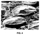
- This Example gives print results as attained with the known method and results attained with the method according to this invention.
- Fig. 4 is an SEM photograph of hot melt ink drops after the drops have been transferred to a receiving material and are fused by a cold pressure roller. The impression of the roller is clearly recognisable in the flattened ink drops. This result is attained with a Tektronix (Xerox) Phaser 300 printer. A description of this printer and the method whereby the photograph according to Fig. 4 has been obtained will be found in the Journal of Imaging Science and Technology, Vol. 42, Number 1, January / February 1998.
- Fig. 5 is an SEM photograph of ink drops transferred to a receiving material using the method according to the present invention.
- ink number 3 of Table 2 was transferred by means of the inkjet printer as described in connection with Fig. 1 to Océ Red Label paper.
- the intermediate element is a roller rubberised with approximately 1.5 mm silicone rubber with a hardness of 80 Shore A. Over this there is applied a top layer of a silicone rubber having a hardness of 25 Shore A, a polar part of the surface tension equal to 1 mN/m, an ink absorption of 4%, a tan ⁇ of 0.02 and a thermal conductivity coefficient of 0.235 W/mK.
- the intermediate element was kept at a temperature of 65°C and a linear pressure of 3800 N/m was exerted in the fused nip. A printing speed of 50 cm/sec was maintained, equal to a speed of 130 A4 sheets per minute.
- the SEM photographs were made with an enlargement comparable to that of Fig. 4, i.e. approximately 500 magnification.
- the electron microscope acceleration voltage used was 15 kV. It will be seen that despite the use of a very soft rubber as transfer element and the absence of a post-fuse step, the ink drops are fused to the receiving material in a comparable manner to that known from the prior art. The ink drops are small, sufficiently spread and follow the paper fibres well. The drops have been found to be resistant to mechanical loads such as gumming, scratching and, to a lesser degree, folding.
- Fig. 1 is a diagram of an inkjet printer according to the present invention.
- the intermediate element 1 is the central feature in this method and in this case is a hollow steel roller rubberised with 1.5 mm silicone rubber over which a top layer of 120 ⁇ m silicone rubber is applied. This top layer satisfies the requirements of the present invention.
- the steel roller is kept at an elevated temperature by a radiator 10 which selectively heats a specific area of the roller. Using a temperature control system (not shown) the temperature is kept constant with a margin of some degrees so that the temperature remains within the bottom and top limits at which the ink is pressure-transferable.
- a typical temperature of the intermediate element is 70°C.
- the transfer element is provided with elements 8 and 9 disposed a short distance apart and serving as cleaning elements in order to remove any ink residues from the intermediate element. For this purpose, said elements are brought into contact with the surface of the intermediate element.
- the printer also comprises a number of printheads 4, 5, 6 and 7, one for each of the colours cyan, magenta, yellow and black, disposed on a carriage 2.
- the type of printhead does not form part of the present invention and in principle any type of printhead can be used which is suitable for transferring hot melt ink to the transfer element.
- a printhead of this kind is known, for example, from US 5 757 404. This is a piezo-electric printhead of the drop-on-demand type and is typically used at a temperature of 130°C and a jetting frequency of 10 kHz.
- the distance between the front of each of the printheads and the intermediate element is about 1 mm.
- the carriage is moved in the indicated direction Y along the surface of the intermediate element and ink is jetted from each of the printheads in the direction of said element.
- the element is rotated an increment further and a following strip is printed fully by again moving the carriage in the Y direction (but in the opposite direction).
- a transfer nip is formed by bringing the companion roller 11 into contact, under a specific pressure, typically 3000 - 4000 N/m, with an intermediate element 1.
- Companion roller 11 is also a steel roller rubberised with the same layer as the intermediate element.
- the receiving material 14, particularly a sheet of paper, is then fed through the transfer nip in the direction X by rotating the transfer element and the companion roller in the indicated directions.
- the paper is preheated to 70° in the preheating station (not shown).
- the transfer nip the image is transferred from the intermediate element to the receiving material.
- the printed receiving material is fed through a guide comprising soft foam rubber rollers 12 and 13 to a finishing station (not shown).
- the method according to this invention is not limited to embodiments in which the image is printed directly by the inkjet printhead on the intermediate element. It is also possible for this to be carried out indirectly, for example using a second intermediate element between the printhead and the first intermediate element. This makes it possible, for example, to print a first image on the first intermediate element (which is printed thereon via the second intermediate element) and then a second image on the second element, whereafter the two images are transferred simultaneously to the receiving material by feeding said material through the nip formed by the first and second intermediate elements.
Landscapes
- Ink Jet (AREA)
- Ink Jet Recording Methods And Recording Media Thereof (AREA)
- Particle Formation And Scattering Control In Inkjet Printers (AREA)
Claims (8)
- Procédé d'impression d'un support de réception à l'aide d'une encre thermofusible, consistant à :caractérisé en ce quechauffer l'encre au-dessus d'une température à laquelle elle est liquide,transférer l'encre liquide dans le sens de l'image sur un élément intermédiaire (1) au moyen d'une tête d'impression à jet d'encre, l'élément intermédiaire (1) ayant une surface contenant un élastomère présentant une tension de surface dont la partie polaire est inférieure ou égale à 20 mN/m,amener le support de réception (14) en contact avec l'élément intermédiaire de telle sorte que l'encre soit transférée de l'élément intermédiaire sur le support de réception,
l'élastomère utilisé a une dureté inférieure à 80 Shore A, a un coefficient de conductivité thermique supérieur à 0,15 W/mK, a une absorption de l'encre inférieure à 10 %, et a une tanδ inférieure à 0,3. - Procédé selon la revendication 1,
dans lequel la partie polaire de la tension de surface est inférieure ou égale à 10 mN/m,
caractérisé en ce que
l'élastomère utilisé a une dureté comprise entre 20 et 60 Shore A, un coefficient de conductivité thermique compris entre 0,15 et 1 W/mK, une absorption de l'encre inférieure à 6 %, et une tanδ comprise entre 0,01 et 0,25. - Procédé selon la revendication 2,
dans lequel la partie polaire de la tension de surface est inférieure ou égale à 5 mN/m,
caractérisé en ce que
l'élastomère utilisé a une dureté comprise entre 25 et 55 Shore A, un coefficient de conductivité thermique compris entre 0,18 et 0,6 W/mK, une absorption de l'encre inférieure à 4 %, et une tanδ comprise entre 0,01 et 0,2. - Procédé selon l'une quelconque des revendications précédentes,
caractérisé en ce que
l'élastomère utilisé est choisi dans le groupe composé du caoutchouc de silicone, du caoutchouc de fluorosilicone et du caoutchouc de perfluoropolyéther. - Procédé selon l'une quelconque des revendications précédentes,
caractérisé en ce que
l'encre utilisée a une énergie de déformation inférieure à 20 x 105 Pa.s à une limite supérieure de température à laquelle l'encre peut être transférée sous pression. - Imprimante à jet d'encre destinée à imprimer un support de réception à l'aide d'une encre thermofusible, cette imprimante à jet d'encre comprenant :caractérisée en ce queune tête d'impression à jet d'encre appropriée pour imprimer l'encre thermofusible dans le sens de l'image,un élément intermédiaire (1) destiné à recevoir l'éncre thermofusible imprimée par la tête d'impression, l'élément intermédiaire (1) ayant une surface contenant un élastomère présentant une tension de surface dont la partie polaire est inférieure ou égale à 20 mN/m,une installation qui permet d'amener en contact le support de réception (14) avec l'élément intermédiaire afin de transférer l'encre sur le support de réception,
l'élastomère a une dureté inférieure à 80 Shore A, un coefficient de conductivité thermique supérieur à 0,15 W/mK, une absorption de l'encre inférieure à 10 % et une tanδ inférieure à 0,3. - Combinaison d'une imprimante selon la revendication 6 et d'une encre ayant une énergie de déformation inférieure à 20 x 105 Pa.s à une limite supérieure de température à laquelle l'encre peut être transférée sous pression.
- Procédé de sélection d'un élastomère utilisé dans le procédé selon l'une quelconque des revendications 1 à 5, consistant à :déterminer la partie polaire de la tension de surface de l'élastomère,déterminer la dureté de l'élastomère,déterminer le coefficient de conductivité thermique de l'élastomère,déterminer l'absorption de l'encre de l'élastomère,déterminer la tanδ de l'élastomère,
l'élastomère étant choisi si, et uniquement si :la partie polaire de la tension de surface est inférieure ou égale à 20 mN/m,la dureté est inférieure à 80 Shore A,le coefficient de conductivité thermique est supérieur à 0,15 W/mK,l'absorption de l'encre est inférieure à 10 %,et la tanδ est inférieure à 0,3.
Applications Claiming Priority (2)
| Application Number | Priority Date | Filing Date | Title |
|---|---|---|---|
| NL1021010 | 2002-07-05 | ||
| NL1021010A NL1021010C2 (nl) | 2002-07-05 | 2002-07-05 | Werkwijze voor het bedrukken van een ontvangstmateriaal met hot melt inkt en een inkjet printer geschikt om deze werkwijze toe te passen. |
Publications (2)
| Publication Number | Publication Date |
|---|---|
| EP1378357A1 EP1378357A1 (fr) | 2004-01-07 |
| EP1378357B1 true EP1378357B1 (fr) | 2005-08-31 |
Family
ID=29720356
Family Applications (1)
| Application Number | Title | Priority Date | Filing Date |
|---|---|---|---|
| EP03077094A Expired - Lifetime EP1378357B1 (fr) | 2002-07-05 | 2003-07-02 | Méthode d'impression d'un matériau récepteur par une encre thermofusible et imprimante par jet d'encre adaptée pour l'application de cette méthode |
Country Status (6)
| Country | Link |
|---|---|
| US (1) | US6905203B2 (fr) |
| EP (1) | EP1378357B1 (fr) |
| JP (1) | JP4372468B2 (fr) |
| AT (1) | ATE303249T1 (fr) |
| DE (1) | DE60301455T2 (fr) |
| NL (1) | NL1021010C2 (fr) |
Families Citing this family (36)
| Publication number | Priority date | Publication date | Assignee | Title |
|---|---|---|---|---|
| NL1021011C2 (nl) * | 2002-07-05 | 2004-01-06 | Oce Tech Bv | Smeltbare inkt voor een inkjet printer en een werkwijze voor het selecteren van een dergelijke inkt. |
| NZ532931A (en) * | 2004-05-14 | 2007-12-21 | Allflex New Zealand | Improvements in animal identification marking |
| JP2006082287A (ja) * | 2004-09-14 | 2006-03-30 | Fuji Xerox Co Ltd | インクジェット記録装置 |
| NL1028546C2 (nl) | 2005-03-15 | 2006-09-18 | Oce Tech Bv | Piezo-inkjetprinter. |
| DE602007003908D1 (de) * | 2006-08-22 | 2010-02-04 | Oce Tech Bv | Bilderzeugungsverfahren, das eine Phasenaustauschtinte auf einem selbstlaminierenden Aufzeichnungsmedium verwendet |
| EP1892115B1 (fr) | 2006-08-22 | 2009-12-23 | Océ-Technologies B.V. | Procédé de formation d'image utilisant une encre à changement de phase sur un matériau auto-laminant |
| EP1950259A1 (fr) * | 2007-01-24 | 2008-07-30 | Océ-Technologies B.V. | Encre fusible pour imprimante à jet d'encre et procédé de sélection d'une telle encre |
| US9452654B2 (en) | 2009-01-07 | 2016-09-27 | Fox Factory, Inc. | Method and apparatus for an adjustable damper |
| US10047817B2 (en) | 2009-01-07 | 2018-08-14 | Fox Factory, Inc. | Method and apparatus for an adjustable damper |
| US10060499B2 (en) | 2009-01-07 | 2018-08-28 | Fox Factory, Inc. | Method and apparatus for an adjustable damper |
| US9033122B2 (en) | 2009-01-07 | 2015-05-19 | Fox Factory, Inc. | Method and apparatus for an adjustable damper |
| US20100170760A1 (en) | 2009-01-07 | 2010-07-08 | John Marking | Remotely Operated Bypass for a Suspension Damper |
| US8857580B2 (en) | 2009-01-07 | 2014-10-14 | Fox Factory, Inc. | Remotely operated bypass for a suspension damper |
| US11306798B2 (en) | 2008-05-09 | 2022-04-19 | Fox Factory, Inc. | Position sensitive suspension damping with an active valve |
| US8627932B2 (en) | 2009-01-07 | 2014-01-14 | Fox Factory, Inc. | Bypass for a suspension damper |
| US8393446B2 (en) | 2008-08-25 | 2013-03-12 | David M Haugen | Methods and apparatus for suspension lock out and signal generation |
| US12491961B2 (en) | 2008-11-25 | 2025-12-09 | Fox Factory, Inc. | Seat post |
| US10036443B2 (en) | 2009-03-19 | 2018-07-31 | Fox Factory, Inc. | Methods and apparatus for suspension adjustment |
| US9140325B2 (en) | 2009-03-19 | 2015-09-22 | Fox Factory, Inc. | Methods and apparatus for selective spring pre-load adjustment |
| US9422018B2 (en) | 2008-11-25 | 2016-08-23 | Fox Factory, Inc. | Seat post |
| US10821795B2 (en) | 2009-01-07 | 2020-11-03 | Fox Factory, Inc. | Method and apparatus for an adjustable damper |
| US11299233B2 (en) | 2009-01-07 | 2022-04-12 | Fox Factory, Inc. | Method and apparatus for an adjustable damper |
| US12122205B2 (en) | 2009-01-07 | 2024-10-22 | Fox Factory, Inc. | Active valve for an internal bypass |
| US9038791B2 (en) | 2009-01-07 | 2015-05-26 | Fox Factory, Inc. | Compression isolator for a suspension damper |
| US8936139B2 (en) | 2009-03-19 | 2015-01-20 | Fox Factory, Inc. | Methods and apparatus for suspension adjustment |
| US8672106B2 (en) | 2009-10-13 | 2014-03-18 | Fox Factory, Inc. | Self-regulating suspension |
| EP2312180B1 (fr) | 2009-10-13 | 2019-09-18 | Fox Factory, Inc. | Appareil pour contrôler un amortisseur hydraulique |
| US10697514B2 (en) | 2010-01-20 | 2020-06-30 | Fox Factory, Inc. | Remotely operated bypass for a suspension damper |
| EP2402239B1 (fr) | 2010-07-02 | 2020-09-02 | Fox Factory, Inc. | Tige de selle réglable |
| EP2530355B1 (fr) | 2011-05-31 | 2019-09-04 | Fox Factory, Inc. | Appareil pour amortissement de suspension sensible au positionnement et/ou réglable |
| EP3567272B1 (fr) | 2011-09-12 | 2021-05-26 | Fox Factory, Inc. | Procédés et appareil de réglage de suspension |
| US9199448B2 (en) * | 2011-12-07 | 2015-12-01 | Xerox Corporation | Imaging drum surface emissivity and heat absorption control methods, apparatus, and systems for reduction of imaging drum temperature variation |
| US11279199B2 (en) | 2012-01-25 | 2022-03-22 | Fox Factory, Inc. | Suspension damper with by-pass valves |
| US10330171B2 (en) | 2012-05-10 | 2019-06-25 | Fox Factory, Inc. | Method and apparatus for an adjustable damper |
| WO2014068108A1 (fr) * | 2012-11-05 | 2014-05-08 | Oce-Technologies B.V. | Méthode de formation d'une image par jet d'encre |
| US10737546B2 (en) | 2016-04-08 | 2020-08-11 | Fox Factory, Inc. | Electronic compression and rebound control |
Family Cites Families (14)
| Publication number | Priority date | Publication date | Assignee | Title |
|---|---|---|---|---|
| JP3041952B2 (ja) | 1990-02-23 | 2000-05-15 | セイコーエプソン株式会社 | インクジェット式記録ヘッド、圧電振動体、及びこれらの製造方法 |
| KR960000982B1 (ko) | 1992-04-07 | 1996-01-15 | 주식회사에스 · 케이 · 씨 | 혐기성 경화형 조성물 |
| US5372852A (en) | 1992-11-25 | 1994-12-13 | Tektronix, Inc. | Indirect printing process for applying selective phase change ink compositions to substrates |
| US5389958A (en) | 1992-11-25 | 1995-02-14 | Tektronix, Inc. | Imaging process |
| US6122794A (en) * | 1996-10-03 | 2000-09-26 | Zodiac Pool Care, Inc. | Swimming pool cleaner component |
| US5777650A (en) | 1996-11-06 | 1998-07-07 | Tektronix, Inc. | Pressure roller |
| DE69937767T2 (de) * | 1998-02-25 | 2008-04-30 | Xerox Corp., Stamford | Apparat und Verfahren zum Schmelzfixieren von Bildern |
| JPH11327315A (ja) * | 1998-05-12 | 1999-11-26 | Brother Ind Ltd | 転写装置及び画像形成装置 |
| NL1009791C2 (nl) | 1998-08-03 | 2000-02-04 | Oce Tech Bv | Inktsamenstelling voor een smeltbare inkt. |
| JP2000103052A (ja) * | 1998-09-29 | 2000-04-11 | Brother Ind Ltd | 画像形成装置 |
| EP1022140B1 (fr) | 1999-01-22 | 2003-04-16 | Océ-Technologies B.V. | Tête d'impression par jet d'encre |
| NL1012549C2 (nl) | 1999-07-09 | 2001-01-10 | Ocu Technologies B V | Inktsamenstelling voor een smeltbare inkt en een werkwijze voor het bedrukken van een substraat met een dergelijke inktsamenstelling. |
| US6386617B1 (en) * | 1999-10-29 | 2002-05-14 | Exatec, Llc. | Closure panel mounting for vehicle window openings |
| US6843559B2 (en) * | 2002-06-20 | 2005-01-18 | Xerox Corporation | Phase change ink imaging component with MICA-type silicate layer |
-
2002
- 2002-07-05 NL NL1021010A patent/NL1021010C2/nl not_active IP Right Cessation
-
2003
- 2003-06-20 JP JP2003175893A patent/JP4372468B2/ja not_active Expired - Fee Related
- 2003-07-02 DE DE60301455T patent/DE60301455T2/de not_active Expired - Lifetime
- 2003-07-02 AT AT03077094T patent/ATE303249T1/de not_active IP Right Cessation
- 2003-07-02 EP EP03077094A patent/EP1378357B1/fr not_active Expired - Lifetime
- 2003-07-03 US US10/612,070 patent/US6905203B2/en not_active Expired - Fee Related
Also Published As
| Publication number | Publication date |
|---|---|
| ATE303249T1 (de) | 2005-09-15 |
| US6905203B2 (en) | 2005-06-14 |
| NL1021010C2 (nl) | 2004-01-06 |
| JP2004034701A (ja) | 2004-02-05 |
| EP1378357A1 (fr) | 2004-01-07 |
| US20040017455A1 (en) | 2004-01-29 |
| JP4372468B2 (ja) | 2009-11-25 |
| DE60301455T2 (de) | 2006-06-14 |
| DE60301455D1 (de) | 2005-10-06 |
Similar Documents
| Publication | Publication Date | Title |
|---|---|---|
| EP1378357B1 (fr) | Méthode d'impression d'un matériau récepteur par une encre thermofusible et imprimante par jet d'encre adaptée pour l'application de cette méthode | |
| US6923853B2 (en) | Meltable ink for an inkjet printer and a method of selecting such an ink | |
| US5389958A (en) | Imaging process | |
| EP0676300B1 (fr) | Méthode et appareil pour contrôler la température d'encres à changement de phase pendant une opération d'impression par transfert | |
| US5614933A (en) | Method and apparatus for controlling phase-change ink-jet print quality factors | |
| US5805191A (en) | Intermediate transfer surface application system | |
| US7322689B2 (en) | Phase change ink transfix pressure component with dual-layer configuration | |
| US6549224B2 (en) | Adjustable printhead loading device and method for document imaging apparatus | |
| US6019045A (en) | Process for the preparation of ink jet process printing plate | |
| EP0604025B1 (fr) | Procédé de formation d'images | |
| US7407278B2 (en) | Phase change ink transfix pressure component with single layer configuration | |
| EP0770498A3 (fr) | Méthode pour l'impression par transfert thermique et matériaux pour l'impression utilisés dans cette méthode | |
| EP2087998B1 (fr) | Élément d'imprimante régulé thermiquement, utilisation d'un matériau en caoutchouc disposant d'un matériau de changement de phase dispersé dessus, imprimante et procédé d'impression | |
| US5821956A (en) | Method to improve solid ink output resolution | |
| WO2008090036A1 (fr) | Encre fusible pour imprimante à jet d'encre et procédé de sélection d'une telle encre | |
| US7325917B2 (en) | Phase change ink transfix pressure component with three-layer configuration | |
| US11628665B2 (en) | Digital ink application module and methods thereof | |
| US9096055B2 (en) | Systems and methods for ink-based digital printing | |
| JPH05201039A (ja) | 画像形成装置 | |
| JPH0776120A (ja) | サーマルヘッドを用いたプリンタの印字濃度補正方法 |
Legal Events
| Date | Code | Title | Description |
|---|---|---|---|
| PUAI | Public reference made under article 153(3) epc to a published international application that has entered the european phase |
Free format text: ORIGINAL CODE: 0009012 |
|
| AK | Designated contracting states |
Kind code of ref document: A1 Designated state(s): AT BE BG CH CY CZ DE DK EE ES FI FR GB GR HU IE IT LI LU MC NL PT RO SE SI SK TR |
|
| AX | Request for extension of the european patent |
Extension state: AL LT LV MK |
|
| 17P | Request for examination filed |
Effective date: 20040707 |
|
| AKX | Designation fees paid |
Designated state(s): AT BE BG CH CY CZ DE DK EE ES FI FR GB GR HU IE IT LI LU MC NL PT RO SE SI SK TR |
|
| GRAP | Despatch of communication of intention to grant a patent |
Free format text: ORIGINAL CODE: EPIDOSNIGR1 |
|
| GRAS | Grant fee paid |
Free format text: ORIGINAL CODE: EPIDOSNIGR3 |
|
| GRAA | (expected) grant |
Free format text: ORIGINAL CODE: 0009210 |
|
| AK | Designated contracting states |
Kind code of ref document: B1 Designated state(s): AT BE BG CH CY CZ DE DK EE ES FI FR GB GR HU IE IT LI LU MC NL PT RO SE SI SK TR |
|
| PG25 | Lapsed in a contracting state [announced via postgrant information from national office to epo] |
Ref country code: SI Free format text: LAPSE BECAUSE OF FAILURE TO SUBMIT A TRANSLATION OF THE DESCRIPTION OR TO PAY THE FEE WITHIN THE PRESCRIBED TIME-LIMIT Effective date: 20050831 Ref country code: IT Free format text: LAPSE BECAUSE OF FAILURE TO SUBMIT A TRANSLATION OF THE DESCRIPTION OR TO PAY THE FEE WITHIN THE PRESCRIBED TIME-LIMIT;WARNING: LAPSES OF ITALIAN PATENTS WITH EFFECTIVE DATE BEFORE 2007 MAY HAVE OCCURRED AT ANY TIME BEFORE 2007. THE CORRECT EFFECTIVE DATE MAY BE DIFFERENT FROM THE ONE RECORDED. Effective date: 20050831 Ref country code: CZ Free format text: LAPSE BECAUSE OF FAILURE TO SUBMIT A TRANSLATION OF THE DESCRIPTION OR TO PAY THE FEE WITHIN THE PRESCRIBED TIME-LIMIT Effective date: 20050831 Ref country code: FI Free format text: LAPSE BECAUSE OF FAILURE TO SUBMIT A TRANSLATION OF THE DESCRIPTION OR TO PAY THE FEE WITHIN THE PRESCRIBED TIME-LIMIT Effective date: 20050831 Ref country code: AT Free format text: LAPSE BECAUSE OF FAILURE TO SUBMIT A TRANSLATION OF THE DESCRIPTION OR TO PAY THE FEE WITHIN THE PRESCRIBED TIME-LIMIT Effective date: 20050831 Ref country code: SK Free format text: LAPSE BECAUSE OF FAILURE TO SUBMIT A TRANSLATION OF THE DESCRIPTION OR TO PAY THE FEE WITHIN THE PRESCRIBED TIME-LIMIT Effective date: 20050831 Ref country code: BE Free format text: LAPSE BECAUSE OF FAILURE TO SUBMIT A TRANSLATION OF THE DESCRIPTION OR TO PAY THE FEE WITHIN THE PRESCRIBED TIME-LIMIT Effective date: 20050831 Ref country code: CH Free format text: LAPSE BECAUSE OF FAILURE TO SUBMIT A TRANSLATION OF THE DESCRIPTION OR TO PAY THE FEE WITHIN THE PRESCRIBED TIME-LIMIT Effective date: 20050831 Ref country code: RO Free format text: LAPSE BECAUSE OF FAILURE TO SUBMIT A TRANSLATION OF THE DESCRIPTION OR TO PAY THE FEE WITHIN THE PRESCRIBED TIME-LIMIT Effective date: 20050831 Ref country code: LI Free format text: LAPSE BECAUSE OF FAILURE TO SUBMIT A TRANSLATION OF THE DESCRIPTION OR TO PAY THE FEE WITHIN THE PRESCRIBED TIME-LIMIT Effective date: 20050831 |
|
| REG | Reference to a national code |
Ref country code: GB Ref legal event code: FG4D Ref country code: CH Ref legal event code: EP |
|
| REG | Reference to a national code |
Ref country code: IE Ref legal event code: FG4D |
|
| REF | Corresponds to: |
Ref document number: 60301455 Country of ref document: DE Date of ref document: 20051006 Kind code of ref document: P |
|
| PG25 | Lapsed in a contracting state [announced via postgrant information from national office to epo] |
Ref country code: GR Free format text: LAPSE BECAUSE OF FAILURE TO SUBMIT A TRANSLATION OF THE DESCRIPTION OR TO PAY THE FEE WITHIN THE PRESCRIBED TIME-LIMIT Effective date: 20051130 Ref country code: SE Free format text: LAPSE BECAUSE OF FAILURE TO SUBMIT A TRANSLATION OF THE DESCRIPTION OR TO PAY THE FEE WITHIN THE PRESCRIBED TIME-LIMIT Effective date: 20051130 Ref country code: BG Free format text: LAPSE BECAUSE OF FAILURE TO SUBMIT A TRANSLATION OF THE DESCRIPTION OR TO PAY THE FEE WITHIN THE PRESCRIBED TIME-LIMIT Effective date: 20051130 Ref country code: DK Free format text: LAPSE BECAUSE OF FAILURE TO SUBMIT A TRANSLATION OF THE DESCRIPTION OR TO PAY THE FEE WITHIN THE PRESCRIBED TIME-LIMIT Effective date: 20051130 |
|
| PG25 | Lapsed in a contracting state [announced via postgrant information from national office to epo] |
Ref country code: ES Free format text: LAPSE BECAUSE OF FAILURE TO SUBMIT A TRANSLATION OF THE DESCRIPTION OR TO PAY THE FEE WITHIN THE PRESCRIBED TIME-LIMIT Effective date: 20051212 |
|
| PG25 | Lapsed in a contracting state [announced via postgrant information from national office to epo] |
Ref country code: PT Free format text: LAPSE BECAUSE OF FAILURE TO SUBMIT A TRANSLATION OF THE DESCRIPTION OR TO PAY THE FEE WITHIN THE PRESCRIBED TIME-LIMIT Effective date: 20060223 |
|
| PG25 | Lapsed in a contracting state [announced via postgrant information from national office to epo] |
Ref country code: HU Free format text: LAPSE BECAUSE OF FAILURE TO SUBMIT A TRANSLATION OF THE DESCRIPTION OR TO PAY THE FEE WITHIN THE PRESCRIBED TIME-LIMIT Effective date: 20060301 |
|
| REG | Reference to a national code |
Ref country code: CH Ref legal event code: PL |
|
| ET | Fr: translation filed | ||
| PG25 | Lapsed in a contracting state [announced via postgrant information from national office to epo] |
Ref country code: IE Free format text: LAPSE BECAUSE OF NON-PAYMENT OF DUE FEES Effective date: 20060703 |
|
| PLBE | No opposition filed within time limit |
Free format text: ORIGINAL CODE: 0009261 |
|
| STAA | Information on the status of an ep patent application or granted ep patent |
Free format text: STATUS: NO OPPOSITION FILED WITHIN TIME LIMIT |
|
| PG25 | Lapsed in a contracting state [announced via postgrant information from national office to epo] |
Ref country code: MC Free format text: LAPSE BECAUSE OF NON-PAYMENT OF DUE FEES Effective date: 20060731 |
|
| 26N | No opposition filed |
Effective date: 20060601 |
|
| REG | Reference to a national code |
Ref country code: IE Ref legal event code: MM4A |
|
| PG25 | Lapsed in a contracting state [announced via postgrant information from national office to epo] |
Ref country code: EE Free format text: LAPSE BECAUSE OF FAILURE TO SUBMIT A TRANSLATION OF THE DESCRIPTION OR TO PAY THE FEE WITHIN THE PRESCRIBED TIME-LIMIT Effective date: 20050831 |
|
| PG25 | Lapsed in a contracting state [announced via postgrant information from national office to epo] |
Ref country code: LU Free format text: LAPSE BECAUSE OF NON-PAYMENT OF DUE FEES Effective date: 20060702 Ref country code: TR Free format text: LAPSE BECAUSE OF FAILURE TO SUBMIT A TRANSLATION OF THE DESCRIPTION OR TO PAY THE FEE WITHIN THE PRESCRIBED TIME-LIMIT Effective date: 20050831 |
|
| PG25 | Lapsed in a contracting state [announced via postgrant information from national office to epo] |
Ref country code: CY Free format text: LAPSE BECAUSE OF FAILURE TO SUBMIT A TRANSLATION OF THE DESCRIPTION OR TO PAY THE FEE WITHIN THE PRESCRIBED TIME-LIMIT Effective date: 20050831 |
|
| REG | Reference to a national code |
Ref country code: FR Ref legal event code: PLFP Year of fee payment: 13 |
|
| PGFP | Annual fee paid to national office [announced via postgrant information from national office to epo] |
Ref country code: FR Payment date: 20150626 Year of fee payment: 13 |
|
| PGFP | Annual fee paid to national office [announced via postgrant information from national office to epo] |
Ref country code: NL Payment date: 20150716 Year of fee payment: 13 |
|
| PGFP | Annual fee paid to national office [announced via postgrant information from national office to epo] |
Ref country code: DE Payment date: 20150721 Year of fee payment: 13 Ref country code: GB Payment date: 20150721 Year of fee payment: 13 |
|
| REG | Reference to a national code |
Ref country code: DE Ref legal event code: R119 Ref document number: 60301455 Country of ref document: DE |
|
| REG | Reference to a national code |
Ref country code: NL Ref legal event code: MM Effective date: 20160801 |
|
| GBPC | Gb: european patent ceased through non-payment of renewal fee |
Effective date: 20160702 |
|
| PG25 | Lapsed in a contracting state [announced via postgrant information from national office to epo] |
Ref country code: NL Free format text: LAPSE BECAUSE OF NON-PAYMENT OF DUE FEES Effective date: 20160801 Ref country code: DE Free format text: LAPSE BECAUSE OF NON-PAYMENT OF DUE FEES Effective date: 20170201 Ref country code: FR Free format text: LAPSE BECAUSE OF NON-PAYMENT OF DUE FEES Effective date: 20160801 |
|
| REG | Reference to a national code |
Ref country code: FR Ref legal event code: ST Effective date: 20170331 |
|
| PG25 | Lapsed in a contracting state [announced via postgrant information from national office to epo] |
Ref country code: GB Free format text: LAPSE BECAUSE OF NON-PAYMENT OF DUE FEES Effective date: 20160702 |