EP1378435A2 - Dispositif d'assistance de changement de vitesse pour transmission de bicyclette - Google Patents
Dispositif d'assistance de changement de vitesse pour transmission de bicyclette Download PDFInfo
- Publication number
- EP1378435A2 EP1378435A2 EP03015313A EP03015313A EP1378435A2 EP 1378435 A2 EP1378435 A2 EP 1378435A2 EP 03015313 A EP03015313 A EP 03015313A EP 03015313 A EP03015313 A EP 03015313A EP 1378435 A2 EP1378435 A2 EP 1378435A2
- Authority
- EP
- European Patent Office
- Prior art keywords
- rotating member
- cam
- motion transmitting
- engaging
- release
- Prior art date
- Legal status (The legal status is an assumption and is not a legal conclusion. Google has not performed a legal analysis and makes no representation as to the accuracy of the status listed.)
- Granted
Links
- 230000005540 biological transmission Effects 0.000 title claims abstract description 81
- 230000033001 locomotion Effects 0.000 claims abstract description 224
- 230000007246 mechanism Effects 0.000 claims abstract description 120
- 230000007935 neutral effect Effects 0.000 claims abstract description 13
- 230000004044 response Effects 0.000 claims description 6
- 230000008878 coupling Effects 0.000 description 23
- 238000010168 coupling process Methods 0.000 description 23
- 238000005859 coupling reaction Methods 0.000 description 23
- 230000008859 change Effects 0.000 description 16
- 230000002093 peripheral effect Effects 0.000 description 6
- 238000004804 winding Methods 0.000 description 5
- 230000007704 transition Effects 0.000 description 4
- 210000005069 ears Anatomy 0.000 description 3
- 230000000284 resting effect Effects 0.000 description 2
- 239000011324 bead Substances 0.000 description 1
- 238000010586 diagram Methods 0.000 description 1
- 230000000694 effects Effects 0.000 description 1
- 230000004048 modification Effects 0.000 description 1
- 238000012986 modification Methods 0.000 description 1
- 230000002028 premature Effects 0.000 description 1
- 230000000717 retained effect Effects 0.000 description 1
Images








Classifications
-
- B—PERFORMING OPERATIONS; TRANSPORTING
- B62—LAND VEHICLES FOR TRAVELLING OTHERWISE THAN ON RAILS
- B62M—RIDER PROPULSION OF WHEELED VEHICLES OR SLEDGES; POWERED PROPULSION OF SLEDGES OR SINGLE-TRACK CYCLES; TRANSMISSIONS SPECIALLY ADAPTED FOR SUCH VEHICLES
- B62M25/00—Actuators for gearing speed-change mechanisms specially adapted for cycles
- B62M25/02—Actuators for gearing speed-change mechanisms specially adapted for cycles with mechanical transmitting systems, e.g. cables, levers
- B62M25/04—Actuators for gearing speed-change mechanisms specially adapted for cycles with mechanical transmitting systems, e.g. cables, levers hand actuated
-
- B—PERFORMING OPERATIONS; TRANSPORTING
- B62—LAND VEHICLES FOR TRAVELLING OTHERWISE THAN ON RAILS
- B62M—RIDER PROPULSION OF WHEELED VEHICLES OR SLEDGES; POWERED PROPULSION OF SLEDGES OR SINGLE-TRACK CYCLES; TRANSMISSIONS SPECIALLY ADAPTED FOR SUCH VEHICLES
- B62M25/00—Actuators for gearing speed-change mechanisms specially adapted for cycles
- B62M25/02—Actuators for gearing speed-change mechanisms specially adapted for cycles with mechanical transmitting systems, e.g. cables, levers
-
- B—PERFORMING OPERATIONS; TRANSPORTING
- B62—LAND VEHICLES FOR TRAVELLING OTHERWISE THAN ON RAILS
- B62M—RIDER PROPULSION OF WHEELED VEHICLES OR SLEDGES; POWERED PROPULSION OF SLEDGES OR SINGLE-TRACK CYCLES; TRANSMISSIONS SPECIALLY ADAPTED FOR SUCH VEHICLES
- B62M25/00—Actuators for gearing speed-change mechanisms specially adapted for cycles
- B62M2025/006—Actuators for gearing speed-change mechanisms specially adapted for cycles with auxiliary shift assisting means
-
- Y—GENERAL TAGGING OF NEW TECHNOLOGICAL DEVELOPMENTS; GENERAL TAGGING OF CROSS-SECTIONAL TECHNOLOGIES SPANNING OVER SEVERAL SECTIONS OF THE IPC; TECHNICAL SUBJECTS COVERED BY FORMER USPC CROSS-REFERENCE ART COLLECTIONS [XRACs] AND DIGESTS
- Y10—TECHNICAL SUBJECTS COVERED BY FORMER USPC
- Y10T—TECHNICAL SUBJECTS COVERED BY FORMER US CLASSIFICATION
- Y10T74/00—Machine element or mechanism
- Y10T74/20—Control lever and linkage systems
- Y10T74/20012—Multiple controlled elements
- Y10T74/20018—Transmission control
- Y10T74/20037—Occupant propelled vehicle
- Y10T74/20043—Transmission controlled by flexible cable
-
- Y—GENERAL TAGGING OF NEW TECHNOLOGICAL DEVELOPMENTS; GENERAL TAGGING OF CROSS-SECTIONAL TECHNOLOGIES SPANNING OVER SEVERAL SECTIONS OF THE IPC; TECHNICAL SUBJECTS COVERED BY FORMER USPC CROSS-REFERENCE ART COLLECTIONS [XRACs] AND DIGESTS
- Y10—TECHNICAL SUBJECTS COVERED BY FORMER USPC
- Y10T—TECHNICAL SUBJECTS COVERED BY FORMER US CLASSIFICATION
- Y10T74/00—Machine element or mechanism
- Y10T74/20—Control lever and linkage systems
- Y10T74/20396—Hand operated
- Y10T74/20402—Flexible transmitter [e.g., Bowden cable]
- Y10T74/2042—Flexible transmitter [e.g., Bowden cable] and hand operator
-
- Y—GENERAL TAGGING OF NEW TECHNOLOGICAL DEVELOPMENTS; GENERAL TAGGING OF CROSS-SECTIONAL TECHNOLOGIES SPANNING OVER SEVERAL SECTIONS OF THE IPC; TECHNICAL SUBJECTS COVERED BY FORMER USPC CROSS-REFERENCE ART COLLECTIONS [XRACs] AND DIGESTS
- Y10—TECHNICAL SUBJECTS COVERED BY FORMER USPC
- Y10T—TECHNICAL SUBJECTS COVERED BY FORMER US CLASSIFICATION
- Y10T74/00—Machine element or mechanism
- Y10T74/20—Control lever and linkage systems
- Y10T74/20396—Hand operated
- Y10T74/20402—Flexible transmitter [e.g., Bowden cable]
- Y10T74/2042—Flexible transmitter [e.g., Bowden cable] and hand operator
- Y10T74/20438—Single rotatable lever [e.g., for bicycle brake or derailleur]
-
- Y—GENERAL TAGGING OF NEW TECHNOLOGICAL DEVELOPMENTS; GENERAL TAGGING OF CROSS-SECTIONAL TECHNOLOGIES SPANNING OVER SEVERAL SECTIONS OF THE IPC; TECHNICAL SUBJECTS COVERED BY FORMER USPC CROSS-REFERENCE ART COLLECTIONS [XRACs] AND DIGESTS
- Y10—TECHNICAL SUBJECTS COVERED BY FORMER USPC
- Y10T—TECHNICAL SUBJECTS COVERED BY FORMER US CLASSIFICATION
- Y10T74/00—Machine element or mechanism
- Y10T74/20—Control lever and linkage systems
- Y10T74/20396—Hand operated
- Y10T74/20474—Rotatable rod, shaft, or post
Definitions
- the assignee's copending application number 10/190,461 discloses an assist mechanism for a bicycle transmission that overcomes such problems. More specifically, that application discloses an assisting apparatus for using power from a rotating member to assist the operation of a bicycle transmission, wherein the assisting apparatus comprises a mounting unit; an input transmission member coupled to the mounting unit, wherein the input transmission member moves between at least a first input position and a second input position; and an output transmission member coupled to the mounting unit, wherein the output transmission member moves between at least a first output position and a second output position.
- a rotating member engaging member moves between a rotating member engaging position and a rotating member disengaging position, and a motion transmitting mechanism transmits motion from the rotating member engaging member to the output transmission member.
- a switching mechanism moves the rotating member engaging member between the rotating member engaging position and the rotating member disengaging position in response to movement of the input transmission member and the output transmission member.
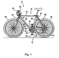
- a fork 42 is rotatably supported within head tube 24, and a front wheel 46 is rotatably supported to the lower end of fork 42.
- the rotational direction of fork 42 and wheel 46 is controlled by a handlebar 50 in a well known manner.
- a rear wheel 54 having a plurality of coaxially mounted freewheel sprockets (not shown) is rotatably supported at the junction of seatstays 34 and chainstays 38, and a pedal assembly 58 supporting a plurality of front (chainwheel) sprockets 62 is rotatably supported within bottom bracket 32.
- three front sprockets 62 rotate coaxially and integrally with pedal assembly 58.
- a chain 66 engages one of the plurality of front sprockets 62 and one of the plurality of freewheel sprockets mounted to rear wheel 54.
- a front derailleur 70 moves chain 66 from one front sprocket 62 to another, and a rear derailleur 74 moves chain 66 from one freewheel sprocket to another. Both operations are well known.
- front derailleur 70 is controlled by pulling and releasing an output control wire 78 coupled to assist mechanism 14, and assist mechanism 14 is controlled by an inner wire 80 of a Bowden-type control cable 82 connected to a shift control device 84 mounted to the left side of handlebar 50.
- Rear derailleur 74 is controlled by a Bowden-type control cable 86 in a conventional manner.
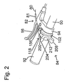
- Fig. 2 is a view of the left side of handlebar 50 showing shift control device 84 in more detail
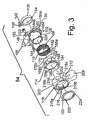
- Fig. 3 is an exploded view of shift control device 84.
- shift control device 84 is mounted between a stationary handgrip 92 and a conventional brake lever bracket 94 that supports a brake lever 98.
- Shift control device 84 comprises a base member 102, a clamping band 106, a biasing component in the form of a spring 110, an intermediate member 114, an actuating component 118, and a retainer 122.
- Base member 102 comprises a tubular portion 126 and a flange portion 130.
- Tubular portion 126 surrounds handlebar 50, and flange portion 130 extends radially outwardly from an inner end of tubular portion 126.
- Clamping band 106 has a locking projection 134 and mounting ears 138 and 142, and the structure fits within an annular recess (not shown) with a locking groove formed at the inner peripheral surface of flange portion 130.
- a screw 144 extends through an opening 148 in flange portion 130 and through mounting ears 138 and 142 and screws into a nut 152 disposed in another opening 153 in flange portion 130 to tighten mounting ears 138 and 142 toward each other and thereby tighten clamping band 106 and fasten base member 102 to handlebar 50.
- Intermediate member 114 is rotatably supported on tubular portion 126 of base member 102 such that spring 110 is disposed between intermediate member 114 and flange portion 130 of base member 102.
- Diametrically opposed projections or stoppers 172 (only one is visible in Fig. 3) forming abutments 172a and 172b extend axially from the inner end of intermediate member 114, and a pair of diametrically opposed intermediate member projections or stoppers 188 forming abutments 188a and 188b extend radially outwardly from an outer peripheral surface 184 of intermediate member 114.
- An end 192 of spring 110 is fitted within a spring opening 194 (which functions as an intermediate member bias engaging component) formed in one of the stoppers 188 for biasing intermediate member 114 clockwise.
- abutments 172a of stoppers 172 engage abutments 160a (which function as base member stoppers) to limit the rotation of intermediate member 114 relative to base member 102.
- inner wire 80 of control cable 82 is under tension as a result of a biasing component disposed in assist apparatus 14.
- actuating component 118 is biased in the counterclockwise direction such that abutments 188a of intermediate member stoppers 188 engage abutments 216a to limit the rotation of actuating component 118 relative to intermediate member 114 and base member 102.
- Retainer 122 is fitted around the outer end of tubular member 126 of base member 102.
- Retainer 122 includes four recesses 220 that are evenly formed on a side surface 224 for engaging four locking tabs 228 that extend radially outwardly from the outer end of tubular portion 126 of base member 102.
- retainer 122 axially fixes actuating component 118 and intermediate member 114 in place on base member 102.
- abutments 160a, 172a, 188a and 216a (and to some extent springs 110 and 232) function as neutral positioning components. Since inner wire 80 is directly coupled to actuating component 118, inner wire 80 likewise is in a transmission control member neutral position at this time.
- Fig. 5 is a more detailed view of assist mechanism 14.
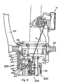
- assist mechanism 14 is mounted to bottom bracket 32, and it includes an input unit 250, a positioning unit 254, and a rotating member engaging unit 258 with a cover 262.
- assist mechanism 14 is used in conjunction with a crank arm 266 that includes an axle mounting boss 270 having a plurality of crank arm splines 274 that nonrotatably engage a plurality of axle splines 278 formed on the end of an axle 282 that is rotatably supported by bottom bracket 32 in a well known manner.
- a drive flange 286 extends radially outwardly from axle mounting boss 270 and supports a pair of diametrically opposed rotating members in the form of drive members 290.
- Drive members 290 have the shape of circular tubes that extend perpendicularly from the side surface 294 of drive flange 286.
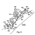
- Fig. 6 is an exploded view of a particular embodiment of input unit 250.
- Input unit 250 includes an input unit mounting member 298, a wire coupling member 302, spring 232, and an input link 306.
- Input unit mounting member 298 has a guide channel 310 for inner wire 80, a central axle opening 314 for receiving an axle 318 (Fig. 10) of positioning unit 254 therethrough, and a pair of diametrically opposed openings 322 (only one opening is visible in Fig. 6).
- Wire coupling member 302 includes a wire winding groove 326 for winding and unwinding inner wire 80, a conventional wire coupler 330 in the form of a screw 334, a wire retainer 338 and a nut 342 for fixing inner wire 80 to wire coupling member 302, and an axle opening 346 for receiving axle 318 of positioning unit 254.
- Input link 306 functions to communicate the rotational position of wire coupling member 302 to positioning unit 254, and it includes an axle mounting portion 350 with an axle receiving opening 352, coupling tabs 354, a radially extending portion 358, and an axially extending coupling portion 362.
- Coupling tabs 354 extend axially from axle mounting portion 350, through openings 322 in input unit mounting member 298, and into corresponding openings (not shown) in wire coupling member 302 so that wire coupling member 302 and input link 306 rotate as a unit. Thus, both wire coupling member 302 and input link 306 will assume neutral, upshift and downshift positions corresponding to the positions of actuating component 118 of shift control device 84.
- Spring 232 has one end 233 mounted to wire coupling member 302 and another end 234 mounted to input unit mounting member 298 so that wire coupling member 302 and input link 306 are biased in the clockwise (wire winding) direction.
- a rotating member engaging member 394 having the shape of a lever in this embodiment, has an arcuate rotating member engaging surface 398 for engaging drive members 290 on crank arm 266.
- a second end portion 392 (Fig. 21) of rotating member engaging member 394 is pivotably connected between a positioning unit interface plate 402 and a support plate 406 (which function as power communicating members) by a pivot shaft 410 (Figs. 8 and 9(A)), thus forming a rotating member engaging link.
- a cam follower 414 is disposed between the first end portion and the second end portion of rotating member engaging member 394, and more specifically in close proximity to pivot shaft 410. Cam follower 414 engages a control cam surface 418 formed by cam slot 386.
- a spring 420 (Fig.
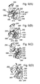
- Fig. 9(A) shows rotating member engaging member 394 in the rotating member disengaging position, wherein drive members 290 rotate with crank arm 266 without causing any effect on assist mechanism 14.
- actuating component 118 of shift control unit 84 is rotated to either the upshift position or the downshift position, then positioning unit interface plate 402 and support plate 406 pivot counterclockwise as shown in Fig. 9(B).
- This causes rotating member engaging member 394 to pivot clockwise around pivot shaft 410, since cam follower 414 is retained within cam slot 386, to the rotating member engaging position shown in Fig. 9(B).
- rotating member engaging surface 398 is disposed in the path of drive members 290, so one of the drive members 290 will contact rotating member engaging surface 398 as shown in Fig.
- Fig. 10 is an enlarged rear cross sectional view of the internal components of positioning unit 254, and Fig. 16(A) is a side view of some of the internal components of positioning unit 254.
- positioning unit 254 includes a base plate 450 supporting one end of a pawl shaft 470; an output transmission member in the form of a rotating member 454 rotatably supported on axle 318 and having a wire winding groove 455 for winding and unwinding output control wire 78 to a plurality of output positions; a biasing component in the form of a spring 456 for biasing rotating member 454 in a wire unwinding direction; a positioning member in the form of a positioning ratchet 458 coupled for integral rotation with rotating member 454; a middle plate 466 supporting the other end of pawl shaft 470; a position maintaining member in the form of a positioning pawl 474 supported by pawl shaft 470 for rotation between a position maintaining position and a position release position and having positioning teeth 475 and 476 (
- Positioning unit 254 further includes a release plate 486 rotatably supported on axle 318 and having a pivot shaft 490 supporting a cam member in the form of a cam plate 494; a motion transmitting member 498 rotatably supported on axle 318; a pawl shaft 502 mounted to motion transmitting member 498; a motion transmitting pawl 506 pivotably supported on pawl shaft 502; a spring 509 for biasing motion transmitting pawl 506 in the counterclockwise direction in Fig.
- FIG. 16(A) another pawl shaft 510 mounted to motion transmitting member 498; a mode change pawl 514 pivotably supported on pawl shaft 510; an input transmission member in the form of a control plate 518 rotatably supported on axle 318; a base plate 522; a pawl shaft 526 mounted to base plate 522 and supporting a switch-off drive control member in the form of a drive control pawl 530; a spring 531 for biasing drive control pawl 530 in the counterclockwise direction in Fig. 16(A); a pawl shaft 534 (Fig.
- Base plate 450, base plate 522 and axle 318 function as mounting units for the various components.
- Fig. 11 is a side view of motion transmitting member 498.
- Motion transmitting member 498 includes a base portion 550, a pawl mounting ear 554 and a motion transmitting arm 558.
- Base portion 550 includes an opening 562 for receiving axle 318 therethrough, a radially outwardly extending projection 566 forming an abutment 570 for contacting drive control pawl 530, and a radially outwardly extending projection 574 forming an abutment 578 for contacting drive control pawl 538.
- Pawl mounting ear 554 includes an opening 582 for mounting pawl shaft 510 (which supports mode change pawl 514), and motion transmitting arm 558 likewise includes an opening 586 for mounting pawl shaft 502 (which supports motion transmitting pawl 506).
- Motion transmitting arm 558 also includes an abutment 588 for contacting drive control pawl 538, and an axially extending rotating member engaging unit interface plate 590 that attaches to positioning unit interface plate 402 through screws 594 as shown in Figs. 8 and 10.
- Fig. 12 is a side view of a particular embodiment of control plate 518.
- Control plate 518 includes an input control member in the form of a base portion 598, a lever arm portion 602, and an input unit interface plate 604.
- Input unit interface plate 604 includes an opening 605 for receiving coupling portion 362 (Fig. 6) of input link 306.
- Base portion 598 includes input control members in the form of radially extending drive control cam surfaces or lobes 606, 610, 614 and 618.
- Drive control cam lobe 606 includes an upper surface 606a and inclined ramps 606b and 606c.
- cam lobe 610 includes an upper surface 610a and inclined ramps 610b and 610c.
- Cam lobe 614 includes an upper surface 614a, an inclined ramp 614b and a transition surface 614c extending from upper surface 614a to an upper surface 618a of cam lobe 618.
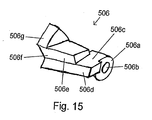
- FIG. 15 is a perspective view of motion transmitting pawl 506.
- Motion transmitting pawl 506 includes a base portion 506a with an opening 506b for receiving pawl shaft 502, a downshift control surface 506c for contacting pawl control surface 660 of middle plate 466 in a manner described below, a positioning ratchet drive surface 506d, a release plate drive surface 506e, and mode change pawl contact surfaces 506f and 506g.
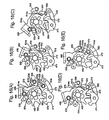
- FIGs. 16(A)-(E) are views illustrating the operation of positioning unit 254 in an upshifting direction.
- positioning unit 254 is in a position such that front derailleur 70 is aligned with the small diameter front sprocket, and it is desired to move front derailleur 70 to the intermediate diameter front sprocket. In the position shown in Fig.
- drive control pawl 538 slides up ramp 614b of cam lobe 614 until drive control pawl 538 disengages from abutment 578 on motion transmitting member 498 and rests on upper surface 614a of cam lobe 614. Since drive control pawl 538 no longer contacts abutment 578, motion transmitting member 498 rotates clockwise until drive control pawl 538 contacts abutment 588, and motion transmitting member 498 is in a "switch on" position as shown in Fig. 16(B). Motion transmitting pawl 506, no longer being held by drive tooth 694 on positioning ratchet 458, rotates counterclockwise and rests on the outer peripheral surface 678 of positioning ratchet 458. The clockwise motion of motion transmitting member 498 is communicated to positioning unit interface plate 402 and support plate 406 in rotating member engaging unit 258 so that rotating member engaging member 394 pivots to the position shown in Fig. 9(B).
- control plate 518 still would be in the upshift position with drive control pawl 538 resting on upper surface 614a of cam lobe 614. In this position, drive control pawl 538 would not be able to engage abutment 578 to stop the rotation of motion transmitting member 498.
- motion transmitting member 498 instead of returning to the switch off position shown in Fig. 16(A), motion transmitting member 498 would continue rotating to the switch on position shown in Fig. 16(B), rotating member engaging member 394 would return to the rotating member engaging position shown in Fig. 9(B), and another shift would result.
- Figs. 17(A)-(E) are views illustrating the operation of positioning unit 254 in a downshifting direction. Some components are shown in transparent view to facilitate understanding of the operation of the components that play an important role in the downshift operation. Assume rotating member 454 is in a position such that front derailleur 70 is aligned with the intermediate diameter front sprocket (the same position shown in Fig. 16(E)), and it is desired to move front derailleur 70 to the small diameter sprocket. Accordingly, in the position shown in Fig.
- the tip of drive control pawl 530 again is supported by the upper surface 606a of cam lobe 606, and the tip of drive control pawl 538 is located at the bottom of ramp 610c of cam lobe 610 such that drive control pawl 538 contacts abutment 578 on motion transmitting member 498.
- Motion transmitting pawl 506 rests on the upper surface of drive tooth 698 on positioning ratchet 458.
- Cam plate 494 which has the overall shape of a rounded and elongated isosceles triangle, includes an axially extending positioning tab 495 that abuts against a side surface 487 of release plate 486 to hold cam plate 494 in the position shown in Fig. 17(A).
- actuating component 118 clockwise (in Fig. 3) to the downshift position so that inner wire 80 is pulled by actuating component 118.
- This causes wire coupling member 302 to rotate counterclockwise in Fig. 6, and this motion is communicated via input link 306 to control plate 518 to rotate control plate 518 counterclockwise as show in Fig. 17(B).
- Counterclockwise rotation of control plate 518 causes drive control pawl 530 to slide down ramp 606b of cam lobe 606 and rotate counterclockwise.
- drive control pawl 538 slides up ramp 610c of cam lobe 610 and rotates clockwise until drive control pawl 538 disengages from abutment 578 on motion transmitting member 498 and rests on upper surface 610a of cam lobe 610. Since drive control pawl 538 no longer contacts abutment 578, motion transmitting member 498 rotates clockwise until drive control pawl 538 contacts abutment 588 and motion transmitting member 498 is in the switch on position shown in Fig. 17(B).
- motion transmitting pawl 506 rotates clockwise by transition surface 618b of cam lobe 618, and mode change pawl 514 rotates clockwise to engage mode change pawl contact surface 506f on motion transmitting pawl 506 to temporarily hold motion transmitting pawl 506 in the position shown in Fig. 17(B).
- the movement of motion transmitting member 498 is communicated to positioning unit interface plate 402 and support plate 406 in rotating member engaging unit 258 so that rotating member engaging member 394 pivots to the position shown in Fig. 9(B).
- cam plate 494 contacts cam roller 478 attached to positioning pawl 474 and causes positioning pawl 474 to rotate in the clockwise direction.
- positioning ratchet 458 and rotating member 454 rotate in the clockwise direction in accordance with the biasing force of spring 456 until positioning tooth 686 abuts against pawl tooth 476 to prevent uncontrolled rotation of positioning ratchet 458 and rotating member 454.
- cam roller 478 reaches the rounded comer or cam lobe 497 of cam plate 494, thus causing cam plate 494 to rotate in the counterclockwise direction as shown in Fig. 17(C).
- This allows positioning pawl 474 to rotate in the counterclockwise direction so that pawl tooth 476 moves away from positioning tooth 686 to allow positioning ratchet 458 and rotating member 454 to continue rotating in the clockwise direction until rotating member 454 is positioned so that front derailleur 70 is aligned with the smaller diameter sprocket.
- release plate 486 and cam plate 494 can be considered a release control mechanism that moves positioning pawl 474 to the position release position as release plate 486 moves toward the second release member position and allows positioning pawl 474 to return to the position maintaining position as release plate 486 continues to move toward the second release member position.
- Another advantageous feature of the preferred embodiment is the manner in which the release plate 486 is allowed to reverse direction even when motion transmitting member 498 is still rotating in the counterclockwise direction.
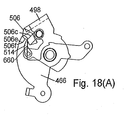
- the motion transmitting member 498 when the motion transmitting member 498 is located in the position shown in Figs. 17(C) and 18(A), downshift control surface 506c of motion transmitting pawl 506 begins to contact the pawl control surface 660 of middle plate 466 as shown in Fig. 18(A). Further rotation of motion transmitting member 498 causes motion transmitting pawl 506 to rotate counterclockwise as shown in Figs. 17(D) and 18(B) which, in turn, causes motion transmitting pawl 506 to disengage from release plate 486.
- control plate 518 When the rider returns actuating component 118 to the neutral position, control plate 518 likewise rotates clockwise back to the neutral position shown in Fig. 17(F).
- drive control pawl 530 slides up ramp 606b of cam lobe 606 and rotates clockwise until drive control pawl 530 disengages from abutment 570 on motion transmitting member 498 and the tip of drive control pawl 530 rests upon upper surface 606a of cam lobe 606.
- drive control pawl 538 slides down ramp 610c of cam lobe 610 and rotates counterclockwise so that the tip of drive control pawl 538 contacts abutment 578 on motion transmitting member 498 as shown in Fig. 17(F).
- Motion transmitting member 498 is now in the switch off position originally shown in Fig. 17(A), but positioning ratchet 458 and rotating member 454 are in the position to align front derailleur 70 with the small diameter front sprocket.
- positioning ratchet 458 would be positioned initially such that pawl tooth 475 abuts against positioning tooth 686.
- positioning pawl 474 rotates clockwise in response to pressure from cam plate 494, pawl tooth 475 clears positioning tooth 686, and positioning ratchet 458 rotates counterclockwise until positioning tooth 690 contacts pawl tooth 476.
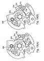
- Figs. 19(A) and 19(B) show a single drive control pawl 700 with pawl teeth 704 and 708.
- Pawl tooth 704 contacts abutment 578 on motion transmitting member 498 when motion transmitting member 498 is in the home position as shown in Fig. 19(A).
- Pawl tooth 708 contacts abutment 570 on motion transmitting member 498 when motion transmitting member 498 is rotating clockwise to the switch off position and control plate 486 has not yet rotated to the neutral position as shown in Fig. 19(B).
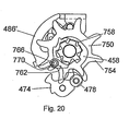
- FIG. 20 shows an embodiment wherein a cam wheel 750 controls the operation of positioning pawl 474.
- cam wheel 750 is coaxially and rotatably mounted relative to positioning ratchet 458.
- Cam wheel 750 includes a plurality of circumferentially disposed cam teeth 754 and a plurality of circumferentially disposed cam drive teeth 758.
- a cam drive pawl 762 is pivotably mounted to a release plate 486' through a pivot shaft 766 and biased in a counterclockwise direction by a spring 770.
- cam drive pawl 762 engages one of the plurality of cam drive teeth 758 and rotates cam wheel 750 in the counterclockwise direction.
- One of the plurality of cam teeth 754 presses against cam roller 478 and causes positioning pawl 474 to rotate in the clockwise direction in the same manner as in the preferred embodiment.
- positioning pawl 474 rotates in the counterclockwise direction to complete the downshift operation.
- Cam drive pawl 762 disengages from the corresponding cam drive tooth 758 when release plate 486' rotates in the clockwise direction.
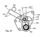
- Fig. 21 shows a situation where the drive member 290 may hinder the proper operation of the assist mechanism 14, and particularly in the downshift direction shown in Figs. 17(A) - 17(F).
- the rider operates shift control device 84 to downshift front derailleur 70 at approximately the same time that drive member 290 is in the vicinity of rotating member engaging member 394.
- drive member 290 may contact the side of rotating member engaging member 394 as shown in Fig. 21. If is assumed that motion transmitting member 498 must rotate 20° from the position shown in Fig. 17(A) to the position shown in Fig.
- Fig. 22 shows an embodiment of a power saving unit 1300 that saves power communicated between the setting mechanism 407 (Fig. 9(A)) and the rotating member engaging member 394 when the setting mechanism 407 attempts to move the rotating member engaging member 394 into the rotating member engaging position and the rotating member engaging member 394 encounters a force that resists the rotating member engaging member 394 being in the rotating member engaging position.
- power saving unit 1300 comprises a power saving element, such as a power saving cam 1304, and a biasing mechanism 1308.
- power saving cam 1304 has the shape of a forked power saving lever with a first end portion 1312 and a second end portion 1316.
- First end portion 1312 is rotatably mounted to cam plate 382 through a pivot shaft 1320, thus creating a power saving link.
- Second end portion 1316 has a bias engaging projection 1324 and a power saving cam projection 1328 with a power saving cam surface 1332.
- Bias engaging projection 1324 engages biasing mechanism 1308 which, in this embodiment, has the form of a spring 1336.
- Spring 1336 is disposed in an opening 1338 formed in cam plate 382, wherein the upper portion of spring 1336 engages bias engaging projection 1324 and the lower portion of spring 1336 engages an abutment 1339 formed at the bottom of opening 1338.
- Spring 1336 biases the second end portion 1316 of power saving cam 1304 to a normal position which, in turn, biases rotating member engaging member 394 toward the rotating member engaging position during the shifting operation.
- a setting mechanism 407' in this embodiment thus comprises positioning unit interface plate 402, support plate 406, cam follower 414 and power saving cam surface 1332.
- rotation of positioning unit interface plate 402 in the manner shown in Figs. 16(A)-16(E) or 17(A)-17(F) causes cam follower 414 to move along power saving cam surface 1332, with spring 1336 biasing power saving cam projection 1328 upwardly.
- This causes rotating member engaging member 394 to rotate around cam follower 414 into the rotating member engaging position shown in Fig. 22 so that rotating member engaging surface 398 contacts drive member 290.
- Fig. 23 shows the power saving unit 1300 in an activated state.
- power saving unit 1300 saves power communicated between the setting mechanism 407' and the rotating member engaging member 394 when the setting mechanism 407' attempts to move rotating member engaging member 394 into the rotating member engaging position and the rotating member engaging member 394 encounters a force that resists the rotating member engaging member 394 being in the rotating member engaging position. More specifically if drive member 290 contacts the side of rotating member engaging member 394 at approximately the same time that setting mechanism 407' is attempting to move rotating member engaging member 394 into the rotating member engaging position, then power saving cam 1316 rotates around pivot shaft 1320 from a normal position shown in Fig. 22 to a power saving position shown in Fig. 23.
- spring 1336 In the power saving position, spring 1336 is in a compressed state, and power from setting mechanism 407' is stored while rotating member engaging member 394 is allowed to move away from the rotating member engaging position as necessary to avoid interference with the drive member 290. Thereafter, spring 1336 expands so that cam follower moves upwardly, and rotating member engaging member rotates around cam follower 414. As a result, motion transmitting member 498 may move into the 20° position necessary to activate mode change pawl 514, and the shifting operation (particularly the downshifting operation) proceeds accordingly when the next drive member 290 engages rotating member engaging surface 398 of rotating member engaging member 394.
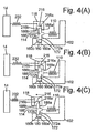
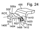
- a motion transmitting pawl 506' includes an elongated portion 1404 extending rearwardly from base 506a, wherein base 506a rotates around a rotational axis ROT.
- Elongated portion 1404 includes a spring mounting hole 1408 for receiving a first end 1410 of a coil spring 1412.
- a second end 1416 of coil spring 1412 is inserted into an opening 1420 in motion transmitting member 498, wherein motion transmitting member 498 functions as a reference member in this embodiment.
- a reference axis REF extends from rotational axis ROT through elongated portion 1404 and spring mounting hole 1408.
- Spring 1412 includes a center of bias CB (Fig. 25(A)) and provides a slight upward bias to elongated portion 1404 which, in turn, creates a counterclockwise bias to motion transmitting pawl 506'.
- assist mechanism 14 operates in the same manner as shown in Figs. 16(A) - 16(E) when an upshift operation is desired.
- Pawl assist apparatus 1400 causes assist mechanism 14 to operate slightly differently from that shown for the downshifting operation in Figs. 17(A) - 17(F).
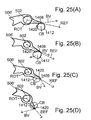
- the operation of pawl assist apparatus 1400 when a downshift operation is desired may be understood by reference to Figs. 25(A) - 25(D).
- Fig. 25(A) pawl assist apparatus 1400 is in the same position shown in Fig. 24. In this position, the center of bias CB and second end 1416 of coil spring 1412 (represented by opening 1420) are disposed on the lower side of reference axis REF, and a biasing vector BV points to the upper side of reference axis REF, thereby applying a counterclockwise bias to motion transmitting pawl 506'.
- release plate 486 is allowed to reverse direction even when motion transmitting member 498 is still rotating in the counterclockwise direction. More specifically, when the motion transmitting member 498 is located in the position shown in Figs. 17(C) and 18(A), downshift control surface 506c of motion transmitting pawl 506' (similar to that shown for motion transmitting pawl 506) begins to contact the pawl control surface 660 of middle plate 466 as shown in Fig. 18(A). Further rotation of motion transmitting member 498 causes motion transmitting pawl 506' to rotate counterclockwise as shown in Figs. 17(D) and 18(B) (around rotational axis ROT in Figs. 24 and 25(A) - 25(C)).
Landscapes
- Engineering & Computer Science (AREA)
- Chemical & Material Sciences (AREA)
- Combustion & Propulsion (AREA)
- Transportation (AREA)
- Mechanical Engineering (AREA)
- Transmission Devices (AREA)
- Gear-Shifting Mechanisms (AREA)
- Structure Of Transmissions (AREA)
Priority Applications (1)
| Application Number | Priority Date | Filing Date | Title |
|---|---|---|---|
| EP03021240.1A EP1394034B1 (fr) | 2002-07-05 | 2003-07-07 | Dispositif d'assistance de changement de vitesse pour transmission de bicyclette |
Applications Claiming Priority (4)
| Application Number | Priority Date | Filing Date | Title |
|---|---|---|---|
| US10/190,461 US6868752B2 (en) | 2002-07-05 | 2002-07-05 | Assisting apparatus for changing speeds in a bicycle transmission |
| US190461 | 2002-07-05 | ||
| US372582 | 2003-02-20 | ||
| US10/372,582 US7090602B2 (en) | 2002-07-05 | 2003-02-20 | Assisting apparatus for changing speeds in a bicycle transmission |
Related Child Applications (1)
| Application Number | Title | Priority Date | Filing Date |
|---|---|---|---|
| EP03021240.1A Division EP1394034B1 (fr) | 2002-07-05 | 2003-07-07 | Dispositif d'assistance de changement de vitesse pour transmission de bicyclette |
Publications (3)
| Publication Number | Publication Date |
|---|---|
| EP1378435A2 true EP1378435A2 (fr) | 2004-01-07 |
| EP1378435A3 EP1378435A3 (fr) | 2007-04-04 |
| EP1378435B1 EP1378435B1 (fr) | 2010-01-20 |
Family
ID=29720951
Family Applications (2)
| Application Number | Title | Priority Date | Filing Date |
|---|---|---|---|
| EP03015313A Expired - Lifetime EP1378435B1 (fr) | 2002-07-05 | 2003-07-07 | Dispositif d'assistance de changement de vitesse pour transmission de bicyclette |
| EP03021240.1A Expired - Lifetime EP1394034B1 (fr) | 2002-07-05 | 2003-07-07 | Dispositif d'assistance de changement de vitesse pour transmission de bicyclette |
Family Applications After (1)
| Application Number | Title | Priority Date | Filing Date |
|---|---|---|---|
| EP03021240.1A Expired - Lifetime EP1394034B1 (fr) | 2002-07-05 | 2003-07-07 | Dispositif d'assistance de changement de vitesse pour transmission de bicyclette |
Country Status (5)
| Country | Link |
|---|---|
| US (2) | US7090602B2 (fr) |
| EP (2) | EP1378435B1 (fr) |
| JP (1) | JP2004034981A (fr) |
| CN (3) | CN100335348C (fr) |
| TW (2) | TWI248901B (fr) |
Families Citing this family (9)
| Publication number | Priority date | Publication date | Assignee | Title |
|---|---|---|---|---|
| US8069749B2 (en) * | 2002-07-05 | 2011-12-06 | Shimano, Inc. | Shift control device for a bicycle transmission |
| FR2878499B1 (fr) * | 2004-12-01 | 2007-02-16 | Salomon Sa | Dispositif de commande de changement de vitesse pour un systeme de transmission par chaine et pignons |
| US8016705B2 (en) * | 2007-04-19 | 2011-09-13 | Shimano Inc. | Bicycle component positioning device |
| US10207772B2 (en) * | 2011-01-28 | 2019-02-19 | Paha Designs, Llc | Gear transmission and derailleur system |
| US9327792B2 (en) * | 2011-01-28 | 2016-05-03 | Paha Designs, Llc | Gear transmission and derailleur system |
| US9651138B2 (en) | 2011-09-30 | 2017-05-16 | Mtd Products Inc. | Speed control assembly for a self-propelled walk-behind lawn mower |
| US9836076B2 (en) * | 2013-01-31 | 2017-12-05 | Shimano Inc. | Bicycle operating device |
| JP2014196060A (ja) * | 2013-03-29 | 2014-10-16 | 株式会社シマノ | 操作装置 |
| US9216794B2 (en) * | 2013-05-23 | 2015-12-22 | Shimano Inc. | Front derailleur |
Citations (2)
| Publication number | Priority date | Publication date | Assignee | Title |
|---|---|---|---|---|
| US5358451A (en) | 1992-02-27 | 1994-10-25 | B. G. Innovation (S.A.R.L.) | Devices enabling shifting of gears on bicycles |
| EP1106496A2 (fr) | 1999-11-30 | 2001-06-13 | Shimano Inc. | Dispositif de commande pour transmission de bicyclette |
Family Cites Families (12)
| Publication number | Priority date | Publication date | Assignee | Title |
|---|---|---|---|---|
| DE3438535A1 (de) * | 1984-10-20 | 1986-04-24 | Fichtel & Sachs Ag, 8720 Schweinfurt | Schalteinrichtung, insbesondere fuer fahrraeder |
| US5020387A (en) | 1985-03-07 | 1991-06-04 | Shimano Industrial Company, Ltd. | Lever shifting device for a bicycle |
| US4872368A (en) * | 1988-07-28 | 1989-10-10 | Orscheln Co. | Push-to-release cable operating apparatus |
| US5217094A (en) * | 1991-08-09 | 1993-06-08 | Atwood Industries, Inc. | Self-adjusting, push-to-release parking brake control |
| JP2594960Y2 (ja) * | 1993-01-29 | 1999-05-24 | 富士機工株式会社 | 自動変速機操作装置のチェック機構 |
| DE69515826T2 (de) | 1994-12-20 | 2000-11-02 | Shimano Inc., Sakai | Steuerungseinrichtung für eine Fahrradgangschaltung mit einer Federeinrichtung |
| JP3086180B2 (ja) * | 1996-09-24 | 2000-09-11 | 株式会社シマノ | 自転車用内装変速装置 |
| US5829313A (en) * | 1997-01-13 | 1998-11-03 | Shimano Inc. | Bicycle derailleur shifting mechanism having indexing configured for use with variety of chain sprocket sets |
| TW358450U (en) * | 1998-02-25 | 1999-05-11 | Ind Res Technology Inst | Electric derailleur for bike |
| US6860171B1 (en) * | 1999-12-29 | 2005-03-01 | Shimano, Inc. | Drive mechanism for a bicycle transmission assist mechanism |
| US6629903B1 (en) * | 2000-04-17 | 2003-10-07 | Shimano Inc. | Bicycle derailleur |
| US6607457B2 (en) | 2001-10-03 | 2003-08-19 | Shimano, Inc. | Assisting apparatus for changing speeds in a bicycle transmission |
-
2003
- 2003-02-20 US US10/372,582 patent/US7090602B2/en not_active Expired - Fee Related
- 2003-07-04 TW TW092118367A patent/TWI248901B/zh active
- 2003-07-04 CN CNB031471560A patent/CN100335348C/zh not_active Expired - Fee Related
- 2003-07-04 TW TW092125467A patent/TW200400897A/zh unknown
- 2003-07-04 CN CN200410001390.0A patent/CN100564150C/zh not_active Expired - Fee Related
- 2003-07-04 CN CN200510054711.8A patent/CN100473580C/zh not_active Expired - Fee Related
- 2003-07-07 US US10/616,170 patent/US7024959B2/en not_active Expired - Fee Related
- 2003-07-07 JP JP2003271597A patent/JP2004034981A/ja not_active Withdrawn
- 2003-07-07 EP EP03015313A patent/EP1378435B1/fr not_active Expired - Lifetime
- 2003-07-07 EP EP03021240.1A patent/EP1394034B1/fr not_active Expired - Lifetime
Patent Citations (2)
| Publication number | Priority date | Publication date | Assignee | Title |
|---|---|---|---|---|
| US5358451A (en) | 1992-02-27 | 1994-10-25 | B. G. Innovation (S.A.R.L.) | Devices enabling shifting of gears on bicycles |
| EP1106496A2 (fr) | 1999-11-30 | 2001-06-13 | Shimano Inc. | Dispositif de commande pour transmission de bicyclette |
Also Published As
| Publication number | Publication date |
|---|---|
| CN1562693A (zh) | 2005-01-12 |
| EP1394034B1 (fr) | 2013-06-26 |
| CN1654271A (zh) | 2005-08-17 |
| TW200404703A (en) | 2004-04-01 |
| JP2004034981A (ja) | 2004-02-05 |
| EP1378435B1 (fr) | 2010-01-20 |
| CN1488547A (zh) | 2004-04-14 |
| EP1394034A2 (fr) | 2004-03-03 |
| US20040025620A1 (en) | 2004-02-12 |
| TWI248901B (en) | 2006-02-11 |
| US20040005949A1 (en) | 2004-01-08 |
| TW200400897A (en) | 2004-01-16 |
| CN100564150C (zh) | 2009-12-02 |
| EP1394034A3 (fr) | 2007-09-05 |
| CN100335348C (zh) | 2007-09-05 |
| EP1378435A3 (fr) | 2007-04-04 |
| US7024959B2 (en) | 2006-04-11 |
| US7090602B2 (en) | 2006-08-15 |
| CN100473580C (zh) | 2009-04-01 |
Similar Documents
| Publication | Publication Date | Title |
|---|---|---|
| US8069749B2 (en) | Shift control device for a bicycle transmission | |
| US6443032B1 (en) | Assisting apparatus for shifting a bicycle transmission | |
| US7472626B2 (en) | Drive mechanism for a bicycle transmission assist mechanism | |
| US6899649B2 (en) | Motor unit for an assisting apparatus for changing speeds in a bicycle transmission | |
| US6868752B2 (en) | Assisting apparatus for changing speeds in a bicycle transmission | |
| US7150205B2 (en) | Handgrip shifter for a bicycle | |
| US20020139218A1 (en) | Bicycle control device | |
| US6607457B2 (en) | Assisting apparatus for changing speeds in a bicycle transmission | |
| US7146874B2 (en) | Shift control device for a bicycle transmission | |
| US6848336B2 (en) | Bicycle shift control device biased to a neutral position | |
| US6835148B2 (en) | Method and apparatus for preventing improper shifting of a bicycle transmission | |
| EP1378435B1 (fr) | Dispositif d'assistance de changement de vitesse pour transmission de bicyclette | |
| EP1495959B1 (fr) | Dispositif d'assistance au changement de vitesse pour transmission de bicyclette | |
| EP1378437B1 (fr) | Dispositif de commande de changement de vitesses pour bicyclette | |
| JP2004034980A (ja) | 自転車用変速機のシフト制御装置及び自転車用変速機のシフト制御装置用インジケータ装置 | |
| JP2004237974A (ja) | 自転車用変速機のシフト制御装置 | |
| JP2004249970A (ja) | 自転車装置用回転制御装置及び自転車変速機操作装置 |
Legal Events
| Date | Code | Title | Description |
|---|---|---|---|
| PUAI | Public reference made under article 153(3) epc to a published international application that has entered the european phase |
Free format text: ORIGINAL CODE: 0009012 |
|
| AK | Designated contracting states |
Kind code of ref document: A2 Designated state(s): AT BE BG CH CY CZ DE DK EE ES FI FR GB GR HU IE IT LI LU MC NL PT RO SE SI SK TR |
|
| AX | Request for extension of the european patent |
Extension state: AL LT LV MK |
|
| RAP1 | Party data changed (applicant data changed or rights of an application transferred) |
Owner name: SHIMANO INC. |
|
| PUAL | Search report despatched |
Free format text: ORIGINAL CODE: 0009013 |
|
| AK | Designated contracting states |
Kind code of ref document: A3 Designated state(s): AT BE BG CH CY CZ DE DK EE ES FI FR GB GR HU IE IT LI LU MC NL PT RO SE SI SK TR |
|
| AX | Request for extension of the european patent |
Extension state: AL LT LV MK |
|
| 17P | Request for examination filed |
Effective date: 20070524 |
|
| 17Q | First examination report despatched |
Effective date: 20070910 |
|
| AKX | Designation fees paid |
Designated state(s): DE |
|
| GRAP | Despatch of communication of intention to grant a patent |
Free format text: ORIGINAL CODE: EPIDOSNIGR1 |
|
| RIN1 | Information on inventor provided before grant (corrected) |
Inventor name: WATARAI, ETUYOSHI Inventor name: HINO, TETSUYA Inventor name: KANEHISA, TAKANORI Inventor name: TABE, KOSHI Inventor name: TETSUKA, TOSHIO Inventor name: SHAHANA, SATOSHI |
|
| GRAS | Grant fee paid |
Free format text: ORIGINAL CODE: EPIDOSNIGR3 |
|
| GRAA | (expected) grant |
Free format text: ORIGINAL CODE: 0009210 |
|
| AK | Designated contracting states |
Kind code of ref document: B1 Designated state(s): DE |
|
| REF | Corresponds to: |
Ref document number: 60331023 Country of ref document: DE Date of ref document: 20100311 Kind code of ref document: P |
|
| PLBE | No opposition filed within time limit |
Free format text: ORIGINAL CODE: 0009261 |
|
| STAA | Information on the status of an ep patent application or granted ep patent |
Free format text: STATUS: NO OPPOSITION FILED WITHIN TIME LIMIT |
|
| 26N | No opposition filed |
Effective date: 20101021 |
|
| PGFP | Annual fee paid to national office [announced via postgrant information from national office to epo] |
Ref country code: DE Payment date: 20110629 Year of fee payment: 9 |
|
| PG25 | Lapsed in a contracting state [announced via postgrant information from national office to epo] |
Ref country code: DE Free format text: LAPSE BECAUSE OF NON-PAYMENT OF DUE FEES Effective date: 20130201 |
|
| REG | Reference to a national code |
Ref country code: DE Ref legal event code: R119 Ref document number: 60331023 Country of ref document: DE Effective date: 20130201 |