EP1378470A2 - Dispositif pour la préhension individuelle, le transport et la dépose positionnée de pièces, en particulier de plaques - Google Patents
Dispositif pour la préhension individuelle, le transport et la dépose positionnée de pièces, en particulier de plaques Download PDFInfo
- Publication number
- EP1378470A2 EP1378470A2 EP03013666A EP03013666A EP1378470A2 EP 1378470 A2 EP1378470 A2 EP 1378470A2 EP 03013666 A EP03013666 A EP 03013666A EP 03013666 A EP03013666 A EP 03013666A EP 1378470 A2 EP1378470 A2 EP 1378470A2
- Authority
- EP
- European Patent Office
- Prior art keywords
- reference plate
- swivel unit
- frame
- workpiece
- circuit board
- Prior art date
- Legal status (The legal status is an assumption and is not a legal conclusion. Google has not performed a legal analysis and makes no representation as to the accuracy of the status listed.)
- Withdrawn
Links
Images

Classifications
-
- B—PERFORMING OPERATIONS; TRANSPORTING
- B65—CONVEYING; PACKING; STORING; HANDLING THIN OR FILAMENTARY MATERIAL
- B65G—TRANSPORT OR STORAGE DEVICES, e.g. CONVEYORS FOR LOADING OR TIPPING, SHOP CONVEYOR SYSTEMS OR PNEUMATIC TUBE CONVEYORS
- B65G47/00—Article or material-handling devices associated with conveyors; Methods employing such devices
- B65G47/74—Feeding, transfer, or discharging devices of particular kinds or types
- B65G47/90—Devices for picking-up and depositing articles or materials
- B65G47/91—Devices for picking-up and depositing articles or materials incorporating pneumatic, e.g. suction, grippers
- B65G47/914—Devices for picking-up and depositing articles or materials incorporating pneumatic, e.g. suction, grippers provided with drive systems incorporating rotary and rectilinear movements
-
- B—PERFORMING OPERATIONS; TRANSPORTING
- B21—MECHANICAL METAL-WORKING WITHOUT ESSENTIALLY REMOVING MATERIAL; PUNCHING METAL
- B21D—WORKING OR PROCESSING OF SHEET METAL OR METAL TUBES, RODS OR PROFILES WITHOUT ESSENTIALLY REMOVING MATERIAL; PUNCHING METAL
- B21D43/00—Feeding, positioning or storing devices combined with, or arranged in, or specially adapted for use in connection with, apparatus for working or processing sheet metal, metal tubes or metal profiles; Associations therewith of cutting devices
- B21D43/20—Storage arrangements; Piling or unpiling
Definitions
- the invention relates to a device for isolated picking up, transporting and positioned placement of workpieces, in particular circuit boards, with the features according to the preamble of protection claim 1.
- a chaining machine for transporting or Stacking of manufacturing parts of various shapes with any surface condition known from a hydraulic horizontal longitudinal guide consists of hydraulic-vertical as a swivel guide Stroke guides with one or a number of grippers, rubber suction cups, electromagnets or mechanically working pliers can be formed, wherein hydraulically operated control cylinders steer the entire system and the grippers and press.
- the invention is based on the object, a device of the aforementioned Art to create, in particular, sheet-like material blanks from any, sufficiently rigid, materials, for example from sheet metal, Separate plastics, cardboard, ceramics, glass or wood and position. It should be ensured that the device both as an integrable unit or as an independent indirect unit can be trained or constructed.
- linear is advantageous in the new device movable carriage with the swivel unit provided there for positioning Picking up, transporting and storing a workpiece or one Board from a so-called unloading unit to a swivel frame a reference plate, but also on the swivel unit individually or to several, arranged at an adjustable distance from each other, expediently unilaterally mounted, extraction arms is provided.
- extraction arms expediently with adjustable, specific to one Provide workpiece or a board with adjustable grippers for positioning Picking up, transporting and storing a workpiece or one Circuit board on a so-called reference plate, on which the isolated workpiece or a board can be further processed.
- Another advantage of the new device is that it is expedient Structural summary of the storage container or the removal unit for the workpieces or blanks to be separated, with the linear guide and Swivel unit and the reference plate to a mechanical unit on a, in particular one-piece frame.
- the frame is expedient and advantageous in the area of the front, the frame corner adjacent to the removal unit is lowered diagonally, so that the entire device is diagonal, so that the in the removal unit stored workpieces or blanks in the lowered corner of the removal unit are gravity-locked in the frame on three sides.
- Another advantage is the clear structure of the device, the one expedient, rational and economical operation and maintenance.
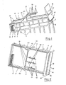
- FIGS. 1 to 7 consists essentially of three, spatially fixed to one another, in particular on a frame 1 and functionally corresponding components, which are explained in more detail below.
- FIG. 1 shows the frame of the device based on the two Longitudinal sides 2 are expediently each provided with a plurality of frame supports 3 is arranged on one side at the same distance from each other.
- 20 denotes a footprint or a floor.
- controllable swivel unit 11 is for individual pick-up, transport and positioning Storage of a workpiece or a board 6 on a so-called reference plate 15 for transfer to one or more advanced processing machines or processing stations.
- swivel unit 11 instead of the hydraulic cylinder 25 to control the swivel unit 11 also so-called pneumatically operated Cylinders or pneumo-hydraulic cylinders can be used expediently. It however, it is also provided that the swivel unit 11 is motorized, in particular is actuated by a motor by means of a servo motor.
- the linear guides 7 are in the case of an indirect drive of the slide 10 with the swivel unit 11 expediently as a so-called surface smooth Shaped rails formed.
- the linear guides 7 are the linear guides 7 as a ball screw drive, or as a rack, or belt or toothed belt, or chain, for expediently designed the engagement of a gear transmission drive or fitted.
- a pneumatic Linear drive in the area of at least one of the two linear guides 7 for Drive of the carriage 10 can be provided with the pivot unit 11.
- the swivel unit 11 is in particular one or more, in particular Conveyor arms 12 arranged parallel to each other.
- the conveyor arms 12 are in particular on one side on the swivel unit shaft 13 expediently lying axially one behind the other, by means of individual screws 19 arranged non-positively.
- Grippers 14 are arranged on a conveyor arm 12 and are secured by means of screws 20 individually, conforming to a workpiece or a circuit board 6 to be separated are non-positively adjustable on a conveyor arm 12.
- the grippers 14, the as a so-called vacuum suction device or vacuum suction mats and / or as Electromagnets or as a mechanically functional gripper 14 can, are to be gripped, transported and used individually Further processing to be deposited on a so-called reference plate 15 or to be positioned workpieces or blanks 6 specifically adjustable a conveyor arm 12 of the pivot unit 11 is arranged.
- the reference plate 15 is advantageously with a frame-shaped passage 16 provided.
- the reference plate 15 is at an angle to the linear guides 4 adjustable on the frame 1.
- 17 denotes a Conveyor belt, which is on the lower edge 18 of the reference plate 15, for transporting a workpiece or a board 6 deposited on the reference plate 15 towards a reference position, a stop 19 is provided.
- This reference position of a workpiece deposited on the reference plate 15 or a board 6 corresponds to the transfer position of the workpiece or one Circuit board 6 to a processing machine, not shown, for example a bending robot or a threading machine, to name just a few application examples of the new device.
- the reference plate 15 also any other expedient spatial position for depositing an occasional slide 10 via the swivel unit 11 delivered and deposited workpiece or board 6, can take over the frame 1. It is also for certain Applications provided that the reference plate 15 is a different tool-specific or has a circuit-specific configuration, and / or that the passage 16 is missing on the reference plate 15.
- 1 denotes the frame with a frame support 3 the frame 1 are, opposite each other, the two to each other parallel linear guides 7 arranged.
- 10 shows the sled with the hydropneumatically operated there, mounted on the shaft 13
- Swivel unit 11 denotes the one-sided on the swivel unit 11 in the arrow directions 21 and 22 adjustable conveyor arms with the on the conveyor arms 12 provided, workpiece or blank conformable adjustable Grippers 14.
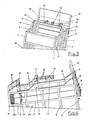
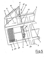
- the pivot unit 11 is, as shown in FIG. 5, down into the frame 1 swung in and has with the, in the present case sucking, Grippers 14 pick up a board 6 from the board stack 23.
- the board stack 23 is expediently fixed in position, in a so-called upright inclined position, stored in frame 1.
- the frame 1 serves as a removal unit or storage container 28 for this purpose here in the context of the invention that for the removal-compliant storage of the isolated tools or blanks 6 to be removed, a removal unit 28 or a storage container is detachably inserted into the frame 1.
- the front board 6 on the board stack 23 by means of compressed air or by means of a spreading magnet, not shown, from the stack of boards 23 separately if the boards 6 on the board stack 23, for example, through moisture residues.
- the board picked up by the grippers 14 of the swivel unit 11 6 is now swiveled up in the direction of arrow 24 and with the slide 10 Move in the direction of arrow 9 on the linear guides 7, as shown in the Fig. 6 can be seen.
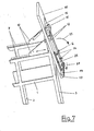
- 1 there denotes the frame with the frame supports 3 on the long sides of the frame 2.
- 7 shows the two linear guides and 10 identifies the slide with the swivel unit 11, the conveyor arms 12 and the grippers 14.6 marks the one picked up and in the direction of arrow 9 the carriage 10 moved by the carriage.
- 25 shows the two hydraulic cylinders for actuating the swivel unit 11.
- the swivel unit 11 engages in this position with their conveyor arms 12 and that of the Grippers 14 fixed board 6 through the passage 16 of the reference plate 15, pivots about the angle of inclination of the reference plate 15 in the direction of the arrow 25 on the reference plate outside 26 and passes the board 6 through Gripper 14 free.
- the board 6 is in this position from that on the reference board 15 provided conveyor belt 17, in the direction of arrow 27 in the reference or transfer position, to the reference plate stop 19, for further processing or transfer to a processing machine or processing device.
- the angle of inclination of the reference plate 15 to the course the linear guide 7 is freely adjustable.
- the linear guide 7 with the carriage 10 and the swivel unit 11 with the conveyor arms 12 and the grippers 14 a frame 1 is constructed as an independent functional unit, and that the removal unit 28 or a storage container for the workpieces or boards 6, as well as the reference plate 15, each as a separate Functional elements are formed, which functionally conform to each other if necessary can be assigned.
Landscapes
- Engineering & Computer Science (AREA)
- Mechanical Engineering (AREA)
- Specific Conveyance Elements (AREA)
- Sheets, Magazines, And Separation Thereof (AREA)
Applications Claiming Priority (2)
| Application Number | Priority Date | Filing Date | Title |
|---|---|---|---|
| DE20210518U DE20210518U1 (de) | 2002-07-05 | 2002-07-05 | Vorrichtung zum vereinzelten Aufnehmen, Transportieren und positioniertem Ablegen von Werkstücken, insbesondere von Platinen |
| DE20210518U | 2002-07-05 |
Publications (2)
| Publication Number | Publication Date |
|---|---|
| EP1378470A2 true EP1378470A2 (fr) | 2004-01-07 |
| EP1378470A3 EP1378470A3 (fr) | 2004-03-17 |
Family
ID=7972944
Family Applications (1)
| Application Number | Title | Priority Date | Filing Date |
|---|---|---|---|
| EP03013666A Withdrawn EP1378470A3 (fr) | 2002-07-05 | 2003-06-17 | Dispositif pour la préhension individuelle, le transport et la dépose positionnée de pièces, en particulier de plaques |
Country Status (2)
| Country | Link |
|---|---|
| EP (1) | EP1378470A3 (fr) |
| DE (1) | DE20210518U1 (fr) |
Families Citing this family (3)
| Publication number | Priority date | Publication date | Assignee | Title |
|---|---|---|---|---|
| DE202016003821U1 (de) | 2016-06-17 | 2016-07-19 | Anchor Lamina Gmbh | Vorrichtung zum Prägen von Abstandssicken in Blechplatinen und Platinenschneidwerkzeug mit wenigstens einer solchen Vorrichtung |
| CN109850572B (zh) * | 2018-11-07 | 2024-08-30 | 无锡奥特维科技股份有限公司 | 搬运装置、搬运方法和串焊机 |
| CN114920165B (zh) * | 2022-05-18 | 2023-10-03 | 南京华易泰电子科技有限公司 | 一种适用于面板的升降搬运结构 |
Family Cites Families (6)
| Publication number | Priority date | Publication date | Assignee | Title |
|---|---|---|---|---|
| DE2431901B2 (de) * | 1974-07-03 | 1977-02-10 | Dr. Karl W. Kaiser KG, 5880 Lüdenscheid | Verfahren und vorrichtung zum ueberfuehren von stehend auf einem stapelbock gestapelten platten, insbesondere glastafeln, auf einen horizontalen tisch |
| FR2577912B1 (fr) * | 1985-02-25 | 1987-03-20 | Smh Alcatel | Distributeur automatique d'articles plats |
| US4925361A (en) * | 1988-12-15 | 1990-05-15 | Western Insulated Glass Company | Method for handling sheet material |
| NL9400162A (nl) * | 1994-02-02 | 1995-09-01 | Capelleveen Bv Geb | Inrichting voor het stapelen en ontstapelen van rechthoekige voorwerpen zoals bijvoorbeeld bakplaten, rijsvormen, kratten, bakblikken en dergelijke. |
| DE19615251C2 (de) | 1996-04-18 | 1999-12-30 | Kb Knecht Gmbh Betriebseinrich | Verfahren und Vorrichtung zum Bearbeiten von Werkstücken in einer Gesenkbiegepresse |
| JPH11217120A (ja) * | 1998-02-02 | 1999-08-10 | Asahi Glass Co Ltd | 板状体の取扱装置 |
-
2002
- 2002-07-05 DE DE20210518U patent/DE20210518U1/de not_active Expired - Lifetime
-
2003
- 2003-06-17 EP EP03013666A patent/EP1378470A3/fr not_active Withdrawn
Also Published As
| Publication number | Publication date |
|---|---|
| DE20210518U1 (de) | 2002-10-31 |
| EP1378470A3 (fr) | 2004-03-17 |
Similar Documents
| Publication | Publication Date | Title |
|---|---|---|
| EP0616874B1 (fr) | Bras de robot pour robot à portique | |
| EP1960155B1 (fr) | Machine-outil | |
| DE212019000006U1 (de) | Vollautomatisches Formungsgerät mit numerischer Steuerung | |
| DE102008017788A1 (de) | Vorrichtung zum Transportieren und Aufnehmen von Werkstückplatten sowie Verfahren zum Transportieren und Aufnehmen von Werkstückplatten | |
| DE102019115634B3 (de) | Sortiersystem für eine Werkzeugmaschine, Werkzeugmaschine und Verfahren zum Sortieren von Schnittteilen | |
| DE112012006565T5 (de) | Verfahren und Vorrichtung zum Entfernen eines im Wesentlichen flachen Werkstücks von der Oberseite eines Stapels aus Werkstücken | |
| DE3622922C2 (fr) | ||
| CN113579761B (zh) | 一种标识牌全自动生产线 | |
| CN211894979U (zh) | 一种板材运输清灰系统 | |
| EP4114590B1 (fr) | Dispositif et procédé pour retourner des tôles | |
| DE4417691C2 (de) | System zum Vorbereiten eines Bogenstapels auf die Verarbeitung in einer bogenverarbeitenden Maschine | |
| DE3613462A1 (de) | Vorrichtung zum be- und entladen eines stapellifts | |
| DE19615251C2 (de) | Verfahren und Vorrichtung zum Bearbeiten von Werkstücken in einer Gesenkbiegepresse | |
| DE19632289A1 (de) | Verfahren und Vorrichtung zur Aufnahme aufeinander gestapelter Materialbögen | |
| DE4407324C2 (de) | Robotarm eines Flächenportalroboters | |
| DE3335928A1 (de) | Einrichtung zum zufuehren von blechzuschnitten zur ziehstufe einer mehrstufenpresse | |
| EP0716993B1 (fr) | Procédé pour dépiler des platines non ferromagnétiques et installation pour sa mise en ouevre | |
| DE102018131785B4 (de) | Verfahren sowie Abstapelelement zur automatisierten Handhabung von Werkstücken | |
| WO2020187481A1 (fr) | Installation de transport pour déplacer au moins une pièce à usiner en forme de plaque | |
| EP1378470A2 (fr) | Dispositif pour la préhension individuelle, le transport et la dépose positionnée de pièces, en particulier de plaques | |
| JP4072227B2 (ja) | 板材搬入出装置 | |
| EP0500525B1 (fr) | Dispositif pour le perçage de plaquettes de circuits imprimés | |
| DE102004054247C5 (de) | Verfahren und Vorrichtung zur Beschickung einer Werkzeugmaschine | |
| EP3851281A1 (fr) | Dispositif de manipulation de plaques d'impression sur une machine d'impression | |
| EP3625156B1 (fr) | Dispositif pour le stockage intermédiaire de pièces en forme de plaques |
Legal Events
| Date | Code | Title | Description |
|---|---|---|---|
| PUAI | Public reference made under article 153(3) epc to a published international application that has entered the european phase |
Free format text: ORIGINAL CODE: 0009012 |
|
| AK | Designated contracting states |
Kind code of ref document: A2 Designated state(s): AT BE BG CH CY CZ DE DK EE ES FI FR GB GR HU IE IT LI LU MC NL PT RO SE SI SK TR |
|
| AX | Request for extension of the european patent |
Extension state: AL LT LV MK |
|
| PUAL | Search report despatched |
Free format text: ORIGINAL CODE: 0009013 |
|
| AK | Designated contracting states |
Kind code of ref document: A3 Designated state(s): AT BE BG CH CY CZ DE DK EE ES FI FR GB GR HU IE IT LI LU MC NL PT RO SE SI SK TR |
|
| AX | Request for extension of the european patent |
Extension state: AL LT LV MK |
|
| STAA | Information on the status of an ep patent application or granted ep patent |
Free format text: STATUS: THE APPLICATION HAS BEEN WITHDRAWN |
|
| 18W | Application withdrawn |
Effective date: 20040913 |