EP1378802B1 - Fixierband und Wärmefixiereinrichtung hiermit für Bilder - Google Patents
Fixierband und Wärmefixiereinrichtung hiermit für Bilder Download PDFInfo
- Publication number
- EP1378802B1 EP1378802B1 EP03013037.1A EP03013037A EP1378802B1 EP 1378802 B1 EP1378802 B1 EP 1378802B1 EP 03013037 A EP03013037 A EP 03013037A EP 1378802 B1 EP1378802 B1 EP 1378802B1
- Authority
- EP
- European Patent Office
- Prior art keywords
- nickel
- heat
- belt
- fixing belt
- fixing
- Prior art date
- Legal status (The legal status is an assumption and is not a legal conclusion. Google has not performed a legal analysis and makes no representation as to the accuracy of the status listed.)
- Expired - Lifetime
Links
- PXHVJJICTQNCMI-UHFFFAOYSA-N Nickel Chemical compound [Ni] PXHVJJICTQNCMI-UHFFFAOYSA-N 0.000 claims description 202
- 239000013078 crystal Substances 0.000 claims description 116
- 229910052759 nickel Inorganic materials 0.000 claims description 105
- 238000005323 electroforming Methods 0.000 claims description 49
- 238000000034 method Methods 0.000 claims description 45
- 230000008569 process Effects 0.000 claims description 20
- CVHZOJJKTDOEJC-UHFFFAOYSA-N saccharin Chemical compound C1=CC=C2C(=O)NS(=O)(=O)C2=C1 CVHZOJJKTDOEJC-UHFFFAOYSA-N 0.000 claims description 7
- 229940081974 saccharin Drugs 0.000 claims description 7
- 235000019204 saccharin Nutrition 0.000 claims description 7
- 239000000901 saccharin and its Na,K and Ca salt Substances 0.000 claims description 7
- 229910017488 Cu K Inorganic materials 0.000 claims description 3
- 229910017541 Cu-K Inorganic materials 0.000 claims description 3
- 238000002441 X-ray diffraction Methods 0.000 claims description 3
- 239000010410 layer Substances 0.000 description 133
- 229910052751 metal Inorganic materials 0.000 description 48
- 239000002184 metal Substances 0.000 description 48
- 238000010438 heat treatment Methods 0.000 description 39
- 239000000463 material Substances 0.000 description 27
- 230000020169 heat generation Effects 0.000 description 26
- 239000000919 ceramic Substances 0.000 description 23
- 230000000052 comparative effect Effects 0.000 description 23
- 229920005989 resin Polymers 0.000 description 23
- 239000011347 resin Substances 0.000 description 23
- NINIDFKCEFEMDL-UHFFFAOYSA-N Sulfur Chemical compound [S] NINIDFKCEFEMDL-UHFFFAOYSA-N 0.000 description 20
- 230000005674 electromagnetic induction Effects 0.000 description 20
- 229910052717 sulfur Inorganic materials 0.000 description 20
- 239000011593 sulfur Substances 0.000 description 20
- 239000012791 sliding layer Substances 0.000 description 17
- 238000000576 coating method Methods 0.000 description 13
- 230000004907 flux Effects 0.000 description 12
- 229920002379 silicone rubber Polymers 0.000 description 12
- YCKRFDGAMUMZLT-UHFFFAOYSA-N Fluorine atom Chemical compound [F] YCKRFDGAMUMZLT-UHFFFAOYSA-N 0.000 description 11
- 239000011737 fluorine Substances 0.000 description 11
- 229910052731 fluorine Inorganic materials 0.000 description 11
- -1 saccharin Chemical compound 0.000 description 11
- 238000010276 construction Methods 0.000 description 9
- 229920001971 elastomer Polymers 0.000 description 8
- 239000005060 rubber Substances 0.000 description 8
- 238000000429 assembly Methods 0.000 description 7
- 230000000712 assembly Effects 0.000 description 7
- 230000015572 biosynthetic process Effects 0.000 description 7
- YNCZNSWQAGQAJY-UHFFFAOYSA-N but-2-yne-1,1-diol Chemical compound CC#CC(O)O YNCZNSWQAGQAJY-UHFFFAOYSA-N 0.000 description 7
- 229920001721 polyimide Polymers 0.000 description 7
- 229910052799 carbon Inorganic materials 0.000 description 6
- 238000001035 drying Methods 0.000 description 6
- 239000009719 polyimide resin Substances 0.000 description 6
- 239000004810 polytetrafluoroethylene Substances 0.000 description 6
- 229920001343 polytetrafluoroethylene Polymers 0.000 description 6
- 239000000758 substrate Substances 0.000 description 6
- 238000012360 testing method Methods 0.000 description 6
- BFKJFAAPBSQJPD-UHFFFAOYSA-N tetrafluoroethene Chemical group FC(F)=C(F)F BFKJFAAPBSQJPD-UHFFFAOYSA-N 0.000 description 6
- VYPSYNLAJGMNEJ-UHFFFAOYSA-N Silicium dioxide Chemical compound O=[Si]=O VYPSYNLAJGMNEJ-UHFFFAOYSA-N 0.000 description 5
- 238000013019 agitation Methods 0.000 description 5
- 229920001577 copolymer Polymers 0.000 description 5
- 238000002474 experimental method Methods 0.000 description 5
- 238000004519 manufacturing process Methods 0.000 description 5
- 238000005259 measurement Methods 0.000 description 5
- 229920001296 polysiloxane Polymers 0.000 description 5
- OKTJSMMVPCPJKN-UHFFFAOYSA-N Carbon Chemical compound [C] OKTJSMMVPCPJKN-UHFFFAOYSA-N 0.000 description 4
- XEEYBQQBJWHFJM-UHFFFAOYSA-N Iron Chemical compound [Fe] XEEYBQQBJWHFJM-UHFFFAOYSA-N 0.000 description 4
- 239000004944 Liquid Silicone Rubber Substances 0.000 description 4
- 239000004696 Poly ether ether ketone Substances 0.000 description 4
- 239000004734 Polyphenylene sulfide Substances 0.000 description 4
- 239000003795 chemical substances by application Substances 0.000 description 4
- 239000011248 coating agent Substances 0.000 description 4
- 229920002530 polyetherether ketone Polymers 0.000 description 4
- 229920000069 polyphenylene sulfide Polymers 0.000 description 4
- 238000003825 pressing Methods 0.000 description 4
- 239000004945 silicone rubber Substances 0.000 description 4
- 239000010935 stainless steel Substances 0.000 description 4
- 229910001220 stainless steel Inorganic materials 0.000 description 4
- QTBSBXVTEAMEQO-UHFFFAOYSA-N Acetic acid Chemical compound CC(O)=O QTBSBXVTEAMEQO-UHFFFAOYSA-N 0.000 description 3
- 239000003638 chemical reducing agent Substances 0.000 description 3
- RTZKZFJDLAIYFH-UHFFFAOYSA-N ether Substances CCOCC RTZKZFJDLAIYFH-UHFFFAOYSA-N 0.000 description 3
- 230000005284 excitation Effects 0.000 description 3
- 238000000465 moulding Methods 0.000 description 3
- KDLHZDBZIXYQEI-UHFFFAOYSA-N palladium Substances [Pd] KDLHZDBZIXYQEI-UHFFFAOYSA-N 0.000 description 3
- 230000002093 peripheral effect Effects 0.000 description 3
- 239000000843 powder Substances 0.000 description 3
- VTYYLEPIZMXCLO-UHFFFAOYSA-L Calcium carbonate Chemical compound [Ca+2].[O-]C([O-])=O VTYYLEPIZMXCLO-UHFFFAOYSA-L 0.000 description 2
- RYGMFSIKBFXOCR-UHFFFAOYSA-N Copper Chemical compound [Cu] RYGMFSIKBFXOCR-UHFFFAOYSA-N 0.000 description 2
- UQSXHKLRYXJYBZ-UHFFFAOYSA-N Iron oxide Chemical compound [Fe]=O UQSXHKLRYXJYBZ-UHFFFAOYSA-N 0.000 description 2
- PWHULOQIROXLJO-UHFFFAOYSA-N Manganese Chemical compound [Mn] PWHULOQIROXLJO-UHFFFAOYSA-N 0.000 description 2
- 229910021586 Nickel(II) chloride Inorganic materials 0.000 description 2
- 239000004695 Polyether sulfone Substances 0.000 description 2
- 239000000654 additive Substances 0.000 description 2
- 230000005540 biological transmission Effects 0.000 description 2
- KGBXLFKZBHKPEV-UHFFFAOYSA-N boric acid Chemical compound OB(O)O KGBXLFKZBHKPEV-UHFFFAOYSA-N 0.000 description 2
- 239000004327 boric acid Substances 0.000 description 2
- 229920006026 co-polymeric resin Polymers 0.000 description 2
- 238000004581 coalescence Methods 0.000 description 2
- 239000011247 coating layer Substances 0.000 description 2
- 239000002131 composite material Substances 0.000 description 2
- 230000006835 compression Effects 0.000 description 2
- 238000007906 compression Methods 0.000 description 2
- 229910052802 copper Inorganic materials 0.000 description 2
- 239000010949 copper Substances 0.000 description 2
- ZYGHJZDHTFUPRJ-UHFFFAOYSA-N coumarin Chemical compound C1=CC=C2OC(=O)C=CC2=C1 ZYGHJZDHTFUPRJ-UHFFFAOYSA-N 0.000 description 2
- 238000000151 deposition Methods 0.000 description 2
- 230000000694 effects Effects 0.000 description 2
- 230000005611 electricity Effects 0.000 description 2
- 238000004070 electrodeposition Methods 0.000 description 2
- 150000002118 epoxides Chemical class 0.000 description 2
- 238000005530 etching Methods 0.000 description 2
- 238000011156 evaluation Methods 0.000 description 2
- 239000003302 ferromagnetic material Substances 0.000 description 2
- 229920005560 fluorosilicone rubber Polymers 0.000 description 2
- 229920006015 heat resistant resin Polymers 0.000 description 2
- 230000006872 improvement Effects 0.000 description 2
- 238000009413 insulation Methods 0.000 description 2
- 229910052742 iron Inorganic materials 0.000 description 2
- 239000004973 liquid crystal related substance Substances 0.000 description 2
- 239000011344 liquid material Substances 0.000 description 2
- 229910052748 manganese Inorganic materials 0.000 description 2
- 239000011572 manganese Substances 0.000 description 2
- 230000007246 mechanism Effects 0.000 description 2
- QMMRZOWCJAIUJA-UHFFFAOYSA-L nickel dichloride Chemical compound Cl[Ni]Cl QMMRZOWCJAIUJA-UHFFFAOYSA-L 0.000 description 2
- KERTUBUCQCSNJU-UHFFFAOYSA-L nickel(2+);disulfamate Chemical compound [Ni+2].NS([O-])(=O)=O.NS([O-])(=O)=O KERTUBUCQCSNJU-UHFFFAOYSA-L 0.000 description 2
- 229910052757 nitrogen Inorganic materials 0.000 description 2
- 230000035699 permeability Effects 0.000 description 2
- 229920001568 phenolic resin Polymers 0.000 description 2
- 239000005011 phenolic resin Substances 0.000 description 2
- 238000005498 polishing Methods 0.000 description 2
- 229920006393 polyether sulfone Polymers 0.000 description 2
- 230000003449 preventive effect Effects 0.000 description 2
- 239000011241 protective layer Substances 0.000 description 2
- 230000009467 reduction Effects 0.000 description 2
- 239000000377 silicon dioxide Substances 0.000 description 2
- 239000000243 solution Substances 0.000 description 2
- 238000003756 stirring Methods 0.000 description 2
- 239000000126 substance Substances 0.000 description 2
- 238000012546 transfer Methods 0.000 description 2
- 239000002966 varnish Substances 0.000 description 2
- 229910000859 α-Fe Inorganic materials 0.000 description 2
- KXGFMDJXCMQABM-UHFFFAOYSA-N 2-methoxy-6-methylphenol Chemical compound [CH]OC1=CC=CC([CH])=C1O KXGFMDJXCMQABM-UHFFFAOYSA-N 0.000 description 1
- LSNNMFCWUKXFEE-UHFFFAOYSA-M Bisulfite Chemical compound OS([O-])=O LSNNMFCWUKXFEE-UHFFFAOYSA-M 0.000 description 1
- 239000004593 Epoxy Substances 0.000 description 1
- UFHFLCQGNIYNRP-UHFFFAOYSA-N Hydrogen Chemical compound [H][H] UFHFLCQGNIYNRP-UHFFFAOYSA-N 0.000 description 1
- 229910000914 Mn alloy Inorganic materials 0.000 description 1
- 229910000990 Ni alloy Inorganic materials 0.000 description 1
- GRYLNZFGIOXLOG-UHFFFAOYSA-N Nitric acid Chemical compound O[N+]([O-])=O GRYLNZFGIOXLOG-UHFFFAOYSA-N 0.000 description 1
- 239000004642 Polyimide Substances 0.000 description 1
- WINXNKPZLFISPD-UHFFFAOYSA-M Saccharin sodium Chemical compound [Na+].C1=CC=C2C(=O)[N-]S(=O)(=O)C2=C1 WINXNKPZLFISPD-UHFFFAOYSA-M 0.000 description 1
- YKTSYUJCYHOUJP-UHFFFAOYSA-N [O--].[Al+3].[Al+3].[O-][Si]([O-])([O-])[O-] Chemical compound [O--].[Al+3].[Al+3].[O-][Si]([O-])([O-])[O-] YKTSYUJCYHOUJP-UHFFFAOYSA-N 0.000 description 1
- 238000010521 absorption reaction Methods 0.000 description 1
- 229910045601 alloy Inorganic materials 0.000 description 1
- 239000000956 alloy Substances 0.000 description 1
- 229910052782 aluminium Inorganic materials 0.000 description 1
- XAGFODPZIPBFFR-UHFFFAOYSA-N aluminium Chemical compound [Al] XAGFODPZIPBFFR-UHFFFAOYSA-N 0.000 description 1
- PNEYBMLMFCGWSK-UHFFFAOYSA-N aluminium oxide Inorganic materials [O-2].[O-2].[O-2].[Al+3].[Al+3] PNEYBMLMFCGWSK-UHFFFAOYSA-N 0.000 description 1
- 239000007864 aqueous solution Substances 0.000 description 1
- 230000008901 benefit Effects 0.000 description 1
- 150000001661 cadmium Chemical class 0.000 description 1
- 229910000019 calcium carbonate Inorganic materials 0.000 description 1
- 239000006229 carbon black Substances 0.000 description 1
- 230000008859 change Effects 0.000 description 1
- 239000004927 clay Substances 0.000 description 1
- 150000001868 cobalt Chemical class 0.000 description 1
- 229910017052 cobalt Inorganic materials 0.000 description 1
- 239000010941 cobalt Substances 0.000 description 1
- GUTLYIVDDKVIGB-UHFFFAOYSA-N cobalt atom Chemical compound [Co] GUTLYIVDDKVIGB-UHFFFAOYSA-N 0.000 description 1
- 239000004020 conductor Substances 0.000 description 1
- 238000001816 cooling Methods 0.000 description 1
- PMHQVHHXPFUNSP-UHFFFAOYSA-M copper(1+);methylsulfanylmethane;bromide Chemical compound Br[Cu].CSC PMHQVHHXPFUNSP-UHFFFAOYSA-M 0.000 description 1
- 229960000956 coumarin Drugs 0.000 description 1
- 235000001671 coumarin Nutrition 0.000 description 1
- 238000005336 cracking Methods 0.000 description 1
- 238000000354 decomposition reaction Methods 0.000 description 1
- 230000007423 decrease Effects 0.000 description 1
- 230000008021 deposition Effects 0.000 description 1
- 238000001514 detection method Methods 0.000 description 1
- 230000006866 deterioration Effects 0.000 description 1
- 239000004205 dimethyl polysiloxane Substances 0.000 description 1
- PTEWEFISOFMTTD-UHFFFAOYSA-L disodium;naphthalene-1,2-disulfonate Chemical compound [Na+].[Na+].C1=CC=CC2=C(S([O-])(=O)=O)C(S(=O)(=O)[O-])=CC=C21 PTEWEFISOFMTTD-UHFFFAOYSA-L 0.000 description 1
- 238000009826 distribution Methods 0.000 description 1
- 239000013013 elastic material Substances 0.000 description 1
- 230000001747 exhibiting effect Effects 0.000 description 1
- 239000011521 glass Substances 0.000 description 1
- 239000010439 graphite Substances 0.000 description 1
- 229910002804 graphite Inorganic materials 0.000 description 1
- 229910052736 halogen Inorganic materials 0.000 description 1
- 150000002367 halogens Chemical class 0.000 description 1
- HCDGVLDPFQMKDK-UHFFFAOYSA-N hexafluoropropylene Chemical group FC(F)=C(F)C(F)(F)F HCDGVLDPFQMKDK-UHFFFAOYSA-N 0.000 description 1
- 230000006698 induction Effects 0.000 description 1
- YOBAEOGBNPPUQV-UHFFFAOYSA-N iron;trihydrate Chemical compound O.O.O.[Fe].[Fe] YOBAEOGBNPPUQV-UHFFFAOYSA-N 0.000 description 1
- 238000003475 lamination Methods 0.000 description 1
- 239000000391 magnesium silicate Substances 0.000 description 1
- 229910052919 magnesium silicate Inorganic materials 0.000 description 1
- 235000019792 magnesium silicate Nutrition 0.000 description 1
- ZADYMNAVLSWLEQ-UHFFFAOYSA-N magnesium;oxygen(2-);silicon(4+) Chemical compound [O-2].[O-2].[O-2].[Mg+2].[Si+4] ZADYMNAVLSWLEQ-UHFFFAOYSA-N 0.000 description 1
- ZAUUZASCMSWKGX-UHFFFAOYSA-N manganese nickel Chemical compound [Mn].[Ni] ZAUUZASCMSWKGX-UHFFFAOYSA-N 0.000 description 1
- WPBNNNQJVZRUHP-UHFFFAOYSA-L manganese(2+);methyl n-[[2-(methoxycarbonylcarbamothioylamino)phenyl]carbamothioyl]carbamate;n-[2-(sulfidocarbothioylamino)ethyl]carbamodithioate Chemical compound [Mn+2].[S-]C(=S)NCCNC([S-])=S.COC(=O)NC(=S)NC1=CC=CC=C1NC(=S)NC(=O)OC WPBNNNQJVZRUHP-UHFFFAOYSA-L 0.000 description 1
- 150000002739 metals Chemical class 0.000 description 1
- 239000000203 mixture Substances 0.000 description 1
- CWQXQMHSOZUFJS-UHFFFAOYSA-N molybdenum disulfide Chemical compound S=[Mo]=S CWQXQMHSOZUFJS-UHFFFAOYSA-N 0.000 description 1
- 229910052982 molybdenum disulfide Inorganic materials 0.000 description 1
- LNOPIUAQISRISI-UHFFFAOYSA-N n'-hydroxy-2-propan-2-ylsulfonylethanimidamide Chemical compound CC(C)S(=O)(=O)CC(N)=NO LNOPIUAQISRISI-UHFFFAOYSA-N 0.000 description 1
- LGQLOGILCSXPEA-UHFFFAOYSA-L nickel sulfate Chemical compound [Ni+2].[O-]S([O-])(=O)=O LGQLOGILCSXPEA-UHFFFAOYSA-L 0.000 description 1
- TXRHHNYLWVQULI-UHFFFAOYSA-L nickel(2+);disulfamate;tetrahydrate Chemical compound O.O.O.O.[Ni+2].NS([O-])(=O)=O.NS([O-])(=O)=O TXRHHNYLWVQULI-UHFFFAOYSA-L 0.000 description 1
- 229910000363 nickel(II) sulfate Inorganic materials 0.000 description 1
- 229910017604 nitric acid Inorganic materials 0.000 description 1
- 230000003287 optical effect Effects 0.000 description 1
- 150000002894 organic compounds Chemical class 0.000 description 1
- TWNQGVIAIRXVLR-UHFFFAOYSA-N oxo(oxoalumanyloxy)alumane Chemical compound O=[Al]O[Al]=O TWNQGVIAIRXVLR-UHFFFAOYSA-N 0.000 description 1
- 239000003002 pH adjusting agent Substances 0.000 description 1
- 229910052763 palladium Inorganic materials 0.000 description 1
- 229910000889 permalloy Inorganic materials 0.000 description 1
- 239000004033 plastic Substances 0.000 description 1
- 229920000435 poly(dimethylsiloxane) Polymers 0.000 description 1
- 229920006122 polyamide resin Polymers 0.000 description 1
- 229920000728 polyester Polymers 0.000 description 1
- 229920001225 polyester resin Polymers 0.000 description 1
- 229920000642 polymer Polymers 0.000 description 1
- 238000007639 printing Methods 0.000 description 1
- 238000000746 purification Methods 0.000 description 1
- 239000010453 quartz Substances 0.000 description 1
- 238000001953 recrystallisation Methods 0.000 description 1
- 239000012763 reinforcing filler Substances 0.000 description 1
- 150000003839 salts Chemical class 0.000 description 1
- 238000007650 screen-printing Methods 0.000 description 1
- 229920002050 silicone resin Polymers 0.000 description 1
- 229910052709 silver Inorganic materials 0.000 description 1
- 239000004332 silver Substances 0.000 description 1
- 229940077386 sodium benzenesulfonate Drugs 0.000 description 1
- HIEHAIZHJZLEPQ-UHFFFAOYSA-M sodium;naphthalene-1-sulfonate Chemical compound [Na+].C1=CC=C2C(S(=O)(=O)[O-])=CC=CC2=C1 HIEHAIZHJZLEPQ-UHFFFAOYSA-M 0.000 description 1
- 239000007787 solid Substances 0.000 description 1
- 238000005507 spraying Methods 0.000 description 1
- WWNBZGLDODTKEM-UHFFFAOYSA-N sulfanylidenenickel Chemical compound [Ni]=S WWNBZGLDODTKEM-UHFFFAOYSA-N 0.000 description 1
- 229940124530 sulfonamide Drugs 0.000 description 1
- 150000003456 sulfonamides Chemical class 0.000 description 1
- 239000002344 surface layer Substances 0.000 description 1
- 230000003746 surface roughness Effects 0.000 description 1
- 229920003002 synthetic resin Polymers 0.000 description 1
- 239000000057 synthetic resin Substances 0.000 description 1
- 239000000454 talc Substances 0.000 description 1
- 229910052623 talc Inorganic materials 0.000 description 1
- XOLBLPGZBRYERU-UHFFFAOYSA-N tin dioxide Chemical compound O=[Sn]=O XOLBLPGZBRYERU-UHFFFAOYSA-N 0.000 description 1
- 229910001887 tin oxide Inorganic materials 0.000 description 1
- 150000003751 zinc Chemical class 0.000 description 1
- GFQYVLUOOAAOGM-UHFFFAOYSA-N zirconium(iv) silicate Chemical compound [Zr+4].[O-][Si]([O-])([O-])[O-] GFQYVLUOOAAOGM-UHFFFAOYSA-N 0.000 description 1
Images




Classifications
-
- G—PHYSICS
- G03—PHOTOGRAPHY; CINEMATOGRAPHY; ANALOGOUS TECHNIQUES USING WAVES OTHER THAN OPTICAL WAVES; ELECTROGRAPHY; HOLOGRAPHY
- G03G—ELECTROGRAPHY; ELECTROPHOTOGRAPHY; MAGNETOGRAPHY
- G03G15/00—Apparatus for electrographic processes using a charge pattern
- G03G15/20—Apparatus for electrographic processes using a charge pattern for fixing, e.g. by using heat
- G03G15/2003—Apparatus for electrographic processes using a charge pattern for fixing, e.g. by using heat using heat
- G03G15/2014—Apparatus for electrographic processes using a charge pattern for fixing, e.g. by using heat using heat using contact heat
- G03G15/2053—Structural details of heat elements, e.g. structure of roller or belt, eddy current, induction heating
- G03G15/2057—Structural details of heat elements, e.g. structure of roller or belt, eddy current, induction heating relating to the chemical composition of the heat element and layers thereof
-
- G—PHYSICS
- G03—PHOTOGRAPHY; CINEMATOGRAPHY; ANALOGOUS TECHNIQUES USING WAVES OTHER THAN OPTICAL WAVES; ELECTROGRAPHY; HOLOGRAPHY
- G03G—ELECTROGRAPHY; ELECTROPHOTOGRAPHY; MAGNETOGRAPHY
- G03G2215/00—Apparatus for electrophotographic processes
- G03G2215/20—Details of the fixing device or porcess
- G03G2215/2003—Structural features of the fixing device
- G03G2215/2016—Heating belt
-
- G—PHYSICS
- G03—PHOTOGRAPHY; CINEMATOGRAPHY; ANALOGOUS TECHNIQUES USING WAVES OTHER THAN OPTICAL WAVES; ELECTROGRAPHY; HOLOGRAPHY
- G03G—ELECTROGRAPHY; ELECTROPHOTOGRAPHY; MAGNETOGRAPHY
- G03G2215/00—Apparatus for electrophotographic processes
- G03G2215/20—Details of the fixing device or porcess
- G03G2215/2003—Structural features of the fixing device
- G03G2215/2016—Heating belt
- G03G2215/2035—Heating belt the fixing nip having a stationary belt support member opposing a pressure member
Definitions
- This invention relates to a fixing belt used in image-forming apparatus such as electrophotographic apparatus and electrostatic-recording apparatus, and an image heat fixing assembly with which unfixed images formed and held on recording mediums are subjected to heat fixing.
- heat roller type assemblies have been in wide use as fixing assemblies with which unfixed images (toner images) of intended information which have been formed and held on recording mediums (such as transfer material sheets, electrofax sheets, electrostatic-recording paper, OHP sheets, printing paper and format paper) by a transfer system or a direct system at a zone where an electrophotographic process, an electrostatic-recording process or a magnetic-recording process is carried out are heat-fixed as permanently fixed images to the recording mediums.
- recording mediums such as transfer material sheets, electrofax sheets, electrostatic-recording paper, OHP sheets, printing paper and format paper
- Such assemblies are commonly those making use of a heat source such as a halogen heater in the roller.
- heating systems those in which a resin belt or metal belt having a small heat capacity is heated using a ceramic heater as a heat source are widely proposed and carried out. More specifically, in such heating systems, it is common to make a heat-resistent belt (fixing belt) held between the ceramic heater as a heating element and a pressure roller as a pressing means to form a nip, and guide a recording medium on which unfixed toner images to be imagewise fixed have been formed and held, into the part between the fixing belt and the pressure roller at the nip so that the recording medium is transported together with the belt while being held between them, to impart the heat of the ceramic heater to the recording medium at the nip via the belt, where the unfixed toner images are heat-and-pressure-fixed to the recording medium surface by the heat and the pressure at the nip.
- fixing belt heat-resistent belt
- on-demand type assemblies can be set up using a low-heat-capacity member as the belt.
- the ceramic heater as a heat source may be electrified only when the image-forming apparatus performs image formation, to bring the heater into a state it has generated heat at a stated fixing temperature.
- the image-forming apparatus can have a short waiting time from power source ON to a image formation performable state (i.e., quick-start performance) and hence can enjoy a low power consumption when it is on stand-by (i.e., power saving).
- an induction heating system in which a metal belt is used and this belt is made to generate heat by itself through eddy currents produced by electromagnetic induction. More specifically, a heating assembly is proposed in which eddy currents are induced in the belt itself or in a conductive member set to be adjacent thereto, by a variation of magnetic flux to make it generate heat by Joule effect.
- This electromagnetic-induction system can set heat generation area closer to the member to be heated, and hence can achieve an improvement in efficiency of the energy to be consumed.
- a method of driving the fixing belt of the fixing assembly of a belt heating system available are, e.g., a method in which a belt brought into pressure contact between a pressure roller and a belt guide which guides the inner surface of the belt is rotated by the rotational driving of the pressure roller (pressure roller drive system), and a method in which in reverse the pressure roller is rotated by the driving of an endless-belt type belt put over a drive roller and a tension roller.
- a fixing belt made of nickel with a surface roughness of less than 0.5 ⁇ m and a thickness of about 40 ⁇ m is disclosed as an example in Japanese Patent Application Laid-open No. 7-13448 ; and in Japanese Patent Application Laid-open No. 6-222695 a fixing belt made of nickel with a thickness of from 10 to 35 ⁇ m, having on its outer periphery a coating layer having releasability and on its inner periphery a resin layer.
- Endless belts made of nickel are readily obtainable by a nickel electroforming process.
- the nickel electroforming process is utilized for the purpose of improving wear resistance or providing glossiness as decorative use.
- the resulting electroformed nickel usually contains sulfur in a large quantity.
- this electroformed nickel is used in the fixing belt, a problem may arise in durability because of embrittlement due to sulfur in a high-temperature condition.
- a fixing belt which is comprised of a nickel metal layer containing 0.04% by weight or less of sulfur and 0.2% by weight or more of manganese, for the purpose of improving heat resistance and durability.
- a fixing belt is proposed which employs as a substrate an endless electroformed sheet formed of a nickel-manganese alloy containing from 0.05 to 0.6% by weight of manganese and having a Vickers microhardness of from 450 to 650.
- the belt heating system in particular, the belt heating system making use of the metal belt, the belt tends to fatigue mechanically because it flexes repeatedly at the nip and in its backward and forward vicinity as the belt itself is rotated. Accordingly, it is sought to more improve the heat resistance and durability.
- PATENT ABSTRACTS OF JAPAN vol. 2000, no. 25, 12 April 2001 (2001-04-12 ) & JP 2001 215820 A discloses a resin coated belt and a method of its manufacture.
- a heat resistant resin layer is formed directly on the metal belt substrate or at least through one rubber layer.
- the metal belt substrate is an endless electroformed nickel belt substrate where the sulfur content is equal to or smaller than 0.2 weight %.
- An object of the present invention is to arrive at a fixing belt having high durability and an image heat fixing assembly having high durability and high reliability, in an image heat fixing assembly which can realize low-energy heating by utilizing a heating element with a small heat capacity.
- the present invention is specified by claim 1 and provides for a fixing belt having at least a release layer and a metal layer formed of electroformed nickel; the electroformed nickel having, in its crystal texture, crystallites having an average size of from 0.05 ⁇ m or more to 0.2 ⁇ m or less.
- the present invention also provides for an image heat fixing assembly having the above fixing belt and a pair of pressure contact members which are mutually in pressure contact via the fixing belt; the inner surface of the fixing belt being slidable on one of the pressure contact members, and an image held on a recording medium being heat-fixed by the aid of the heat conducted from the fixing belt.
- the present invention still also provides for an image heat fixing assembly having a magnetic-flux generation means which produces a magnetic flux, and the above fixing belt generates heat in virtue of the magnetic flux produced by the magnetic-flux generation means to heat and fix the image held on a recording medium.
- the crystallites in the crystal texture of the electroformed nickel are made to have an average size of from 0.05 ⁇ m or more to 0.2 ⁇ m or less. This makes it possible to provide a fixing belt having superior high durability, in particular, durability at high temperature, and an image heat fixing assembly having high durability and high reliability.
- the fixing belt arrived at by the present invention has at least a release layer and a metal layer formed of electroformed nickel.
- the electroformed nickel has, in its crystal texture, crystallites having an average size of from 0.05 ⁇ m or more to 0.2 ⁇ m or less.
- the crystallites in the crystal texture of the electroformed nickel may preferably have an average size of 0.07 ⁇ m or more, and more preferably 0.08 ⁇ m or more.
- the crystallites in the crystal texture of the electroformed nickel may also preferably have an average size of 0.15 ⁇ m or less, and more preferably 0.12 ⁇ m or less.
- making the crystallites in the crystal texture of the electroformed nickel have the average size of from 0.05 ⁇ m or more to 0.2 ⁇ m or less can ensure sufficient heat resistance and durability.
- the electroformed nickel may also preferably have, in its sectional crystal texture, crystal grains having an average size [(b + a)/2] of from 0.1 ⁇ m or more to 3 ⁇ m or less where the length of a crystal grain is represented by b and the breadth thereof by a, and its area percentage occupied by texture in which the crystal shape factor which is the ratio (b/a) of length b to breadth a of a crystal grain is 2 or less may preferably be 50% or more, and more preferably 80% or more.
- the electroformed nickel may further preferably have, in its sectional crystal texture, crystal grains having an average size [(b + a)/2] of from 0.5 ⁇ m or more to 1.5 ⁇ m or less, and its area percentage occupied by texture in which the crystal shape factor which is the ratio (b/a) of length b to breadth a of a crystal grain is from about 0.8 to 1.3 may particularly preferably be 80% or more.
- the crystal texture may preferably be one forming grain arrangement having a regularity.
- the crystal texture having a regularity is advantageous in respect of flexibility, and suits with the fixing belt, which is required to have flexing properties.
- the average size of crystal grains are defined as (b + a)/2 and the shape factor as b/a where the length of a crystal grain is represented by b and the breadth thereof by a.
- the length (b) refers to the maximum length of a crystal grain
- the breadth (a) refers to the maximum length thereof in the direction perpendicular to the length (b).
- the regularity of the sectional crystal texture is also defined as follows: With respect to each of crystal grains at optional three positions, the scattering of angles to the direction of growth in length of 10 crystal grains each which are continuously contiguous in the direction vertical to the direction of growth of crystal grains (the direction of electric current at the time of electroforming) is 30° or less.
- the electroformed nickel is formed in a film from a Watts bath of nickel sulfate or a nickel sulfamate bath, kept at 70°C or below. Its formation includes processes such as the formation and growth of nuclei at the mold surface, the formation of crystallites, and the formation of crystal grains by coalescence of the crystallites. Where a metal is electrodeposited by dissolving the anode, the electrodeposited metal usually shows columnar structure having axes in the direction of electric current, i.e., the direction vertical to the cathode (mold).
- the interior of columnar product has a structure of fine crystals.
- a fine-crystal texture is a texture consisting of crystallites having no orientation and having a small size, without coming to be crystal grains.
- the sectional crystal texture is a fine-crystal texture, a columnar texture or a dendritic texture.
- electroformed nickel having such texture has been used.
- the electroformed nickel as described above is used. This can bring an improvement in durability to ensure sufficient heat resistance and durability.
- the crystal texture having regularity is advantageous in respect of flexibility, and suits with the fixing belt, which is required to have flexing properties.
- the crystal texture of the electroformed nickel comes to fine-crystal or acicular texture.
- the size of crystallites is the same as the size of crystal grains.
- the crystallites have an average size of more than 0.2 ⁇ m, the crystal texture of the electroformed nickel comes to a coarse texture.
- the crystal texture of the electroformed nickel may come to fine-crystal texture to cause a problem in regard to the flexibility of the fixing belt.
- the crystal texture of the electroformed nickel may come to a coarse columnar texture, so that the fixing belt may not satisfy the basic properties (tensile strength and hardness) required in its extensive operation (running), and may come to tend to be destroyed by the flexing of the belt.
- making the crystallites in the sectional crystal texture have the average size of from 0.1 ⁇ m or more to 3 ⁇ m or less can ensure sufficient durability.
- the crystal texture of the electroformed nickel may come to coarse columnar texture to cause ill effects on the strength, flexibility, running time and so forth required in the belt.
- the fixing belt of the present invention is described below.
- Fig. 2 is a diagrammatic view showing an example of the layer construction of a fixing belt 10 in this embodiment.
- the fixing belt 10 of this embodiment has a composite structure made up of a metal layer 1 constituted of an electroformed-nickel endless belt serving as a base layer, an elastic layer 2 laminated to the outer surface of the metal layer 1, a release layer 3 further laminated to the outer surface of the elastic layer 2, and a sliding layer 4 laminated to the inner surface of the metal layer 1.
- the sliding layer 4 is on the inner surface side (belt guide side)
- the release layer 3 is on the outer surface side (pressure roller side).
- a primer layer (not shown) for bonding may be provided between the metal layer 1 and the elastic layer 2, between the elastic layer 2 and the release layer 3 and between the metal layer 1 and the sliding layer 4.
- the primer layer may be formed using a known material of a silicone type, an epoxy type, a poly(amide-imide) type or the like, and may usually be in a thickness of approximately from 1 ⁇ m to 10 ⁇ m.
- Fig. 3 is a diagrammatic view showing another example of the layer construction of a fixing belt 10' in this embodiment.
- the fixing belt 10' of this embodiment has a composite structure made up of a metal layer 1' constituted of an electroformed-nickel endless belt serving as a base layer, a release layer 3' laminated to the outer surface of the metal layer 1', and a sliding layer 4 laminated to the inner surface of the metal layer 1'.
- the sliding layer 4' is on the inner surface side (belt guide side)
- the release layer 3' is on the outer surface side (pressure roller side).
- a primer layer (not shown) for bonding may be provided between the metal layer 1' and the release layer 3' and between the metal layer 1' and the sliding layer 4'.
- the same one as that in the belt shown in Fig. 2 may be provided.
- the fixing belt may have such a form as the above in which the elastic layer is omitted.
- the metal layer 1 or 1' constituted of an electroformed-nickel endless belt functions as a heat generation layer exhibiting electromagnetic-induction heat generation properties.
- an alternating magnetic flux acts on the metal layer 1 or 1' to cause eddy currents in the metal layer 1 or 1', so that the metal layer 1 o 1' generates heat.
- This heat is conducted to the fixing belt 10 or 10' via the elastic layer 2 and release layer 3 or via the release layer 3', and the fixing belt 10 or 10' heats a recording medium fed to a fixing nip N, where the heat fixing of toner images is performed.
- the fixing belt 10 or 10' of the present invention may also be used in a belt heating system making use of a ceramic heater. As described later, in this case, the heat of the ceramic heater is imparted to the recording medium via the fixing belt 10 or 10', so that the toner images are heat-fixed to the surface of the recording medium.
- the metal layer 1 is formed of nickel (inclusive of an alloy thereof) grown on the surface or back of a mold by an electroforming process by immersing in an electroforming bath a cylindrical mold made of SUS stainless steel or the like. As described above, in the crystal texture of this electroformed nickel, the crystallites have the average size of from 0.05 ⁇ m or more to 0.2 ⁇ m or less.
- the electroformed nickel may also preferably have, in its sectional crystal texture, crystal grains having an average size [(b+ a)/2] of from 0.1 ⁇ m or more to 3 ⁇ m or less where the length of a crystal grain is represented by b and the breadth thereof by a, and the area percentage occupied by texture in which the crystal shape factor which is the ratio (b/a) of length b to breadth a of a crystal grain is 2 or less may preferably be 50% or more.
- the size of crystallites of the electroformed nickel is measured with an X-ray diffraction apparatus on Ni (111) diffraction plane and using characteristic X-ray Cu-K (wavelength: 1.5405620 A), and is found by including in the Hall's equation the results of measurement of the extent (integral width) of the diffraction profile.
- the crystallites of the electroformed nickel have no in-plane orientation because the manner of orientation does not change depending on the direction of the sample when their size is measured changing the direction of the plane of the measuring sample or of the plane parallel to the mold.
- the sample may be stuck to a plastic plate in a flat state to make measurement in any desired direction.
- the breadth a and length b of the sectional crystal texture 50 pieces of crystal texture are picked up at random from an SEM (scanning electron microscope) photograph of the sectional crystal texture of the electroformed nickel to measure them. Then, on the basis of the measured values obtained, an average value of the size (a + b)/2 of the crystal grains and an average value of the shape factor b/a thereof are found.
- the sectional crystal texture of the electroformed nickel is considered to be texture formed by the coalescence of crystallites.
- the size of crystallites of coatings, i.e., electroformed materials (electroformed nickel) formed by the electroforming does not remarkably differ among fine-crystal texture, columnar texture, dendritic texture and granular texture, and is said to be from several nm to tens of nm.
- the over-voltage is high in the electroforming process or the brightener is added in a large quantity, the rate of deposition of atoms comes faster than the rate of crystal growth and, correspondingly thereto, the rate of nuclei formation comes higher, so that the size of crystallites becomes 0.05 ⁇ m or less to come into fine-crystal texture.
- the electroformed nickel may preferably be one in which the sectional crystal texture having an optimum crystal texture size is composed of grain arrangement having a given regularity.
- Such electroformed nickel can be obtained by controlling the composition of an electroforming bath and the process of electroforming.
- the electroformed-nickel endless belt of the present invention may also contain, in addition to nickel, element(s) such as sulfur, carbon, cobalt, manganese and/or iron.
- the sulfur which may become deposited in nickel electroforming may preferably be in a content of 0.03% by weight or less, and more preferably 0.02% by weight or less.
- the sulfur component in nickel electroforming is an essential component which decreases electroforming stress and improves molding precision, but on the other hand it damages flexibility, and elasticity at high temperature, and is closely concerned in a phenomenon of break due to metal fatigue. If the sulfur is present in too large quantity, the sulfur may form brittle films around nickel grain boundaries in a high-temperature condition, so that the crystal boundaries of electroformed nickel may come into discontinuity, tending to cause brittle fracture in some cases.
- There are no particular limitations on the lower limit of the content of sulfur which, usually, is about 0.001% by weight.
- the electroformed nickel is produced by an electroforming process using as the cathode a mold made of, e.g., stainless steel.
- a mold made of, e.g., stainless steel.
- any known nickel electroforming bath as exemplified by a sulfamic acid type may be used. Additives such as a pH adjuster, a pit preventive agent and a brightener may also appropriately be added.
- the nickel electroforming bath may include, e.g., a nickel electroforming bath composed of from 300 to 450 g/L of nickel sulfamate, from 0 to 30 g/L of nickel chloride and from 30 to 45 g/L of boric acid.
- electroforming bath temperature, cathode current density and so forth may be controlled, whereby the desired electroformed nickel comprised of nickel or a nickel alloy can be obtained.
- the electroforming process may also differ depending on the electroforming bath to be used, Usually, it may preferably be carried out at an electroforming bath temperature of approximately from 45 to 60°C and a cathode current density of approximately from 1 to 30 A/dm 2 .
- additives called a stress reducer or primary brightener such as saccharin, sodium benzenesulfonate or sodium naphthalenesulfonate and a secondary brightener such as 2-butine-1,4-diol, coumarin or diethyltriamine are added to the electroforming bath so that the electrodeposition stress is reduced to improve molding precision.
- a stress reducer or primary brightener such as saccharin, sodium benzenesulfonate or sodium naphthalenesulfonate
- a secondary brightener such as 2-butine-1,4-diol, coumarin or diethyltriamine
- the primary brightener (stress reducer) makes the crystals of coatings fine and imparts glossiness thereto. Meanwhile, the secondary brightener imparts leveling and glossiness to coatings.
- the primary brightener produces compression stress in coatings, but the secondary brightener imparts tensile stress to coatings.
- chief primary brighteners sulfonic acid, sulfonamide, sodium naphthalenedisulfonate and so forth are used.
- the crystallite size and sectional crystal texture of the electroformed nickel is influenced by the type and amount of the brightener to be added to electroforming bath, the current density of electric current flowed to the cathode (mold), and the flow velocity of electroforming bath in the vicinity of the cathode, and can be made optimum by controlling parameters of these.
- the sulfur becomes deposited in a large quantity together with the electrodeposition of nickel.
- the sulfur present on the outermost surface of electroformed nickel acts as nuclei of nickel crystals.
- Such co-deposition of sulfur in a large quantity makes the crystal texture of electroformed nickel into fine crystals.
- the electroformed nickel is heated to 200°C or above, the sulfur present in nickel crystals segregate at nickel grain boundaries, and sulfur brittle films are formed at the nickel grain boundaries. Hence, microcracks tend to occur at the nickel grain boundaries in the state the stress acts repeatedly as in the case of the fixing belt, tending to result in early break of the fixing belt.
- the addition of, e.g., butinediol, having a carbon triple bond, to the nickel electroforming bath makes the electroformed nickel have crystals oriented predominantly to (200)-plane, where, in the sectional crystal texture, the crystal grains arrange along the mold surface and the film growth direction.
- the butinediol is added to the electroforming bath in a large quantity, any residual stress of electroformed nickel comes to an excess tensile stress to make it difficult to manufacture the fixing belt, tending to cause a lowering in the durability of the fixing belt.
- the amount of the brightener to be added it is selected to add 0.1 g/L or less of saccharin and 1 g/L or less of butinediol to the electroforming bath. It is preferable to add the saccharin in an amount of 0.05 g/L or less and the butinediol in an amount of 0.5 g/L or less.
- Electroformed nickel having a small internal stress is also obtainable by controlling electroforming process parameters, without adding any brightener at all to the electroforming bath. In such a case, however, the crystal texture tends to come coarse, also not to achieve the hardness required in the fixing belt.
- the lower limit of the amount of the brightener to be added it is selected to add 0.005 g/L or more of saccharin used as a first brightener and 0.05 g/L or more of butinediol used as a second brightener, to the electroforming bath.
- the electric current flowed to the cathode (mold) may preferably be at a current density of 30 A/dm 2 or less, and more preferably 20 A/dm 2 or less. If the electric current flowed to the cathode (mold) is at too high current density, the nickel may be deposited at a high rate, but its crystal grains tend to come coarse. Also, the electric current flowed to the cathode (mold) may preferably be at a current density of 1 A/dm 2 or more, and more preferably 4 A/dm 2 or more. If the electric current flowed to the cathode (mold) is at too low current density, the electroformed nickel tends to have fine-crystal texture or dendritic texture.
- the electroforming bath flow velocity in respect to the mold surface it may preferably be 0.25 m/sec or more, and more preferably 0.5 m/sec or more. If the electroforming bath flow velocity in respect to the mold surface is too low, hydrogen gas produced at the mold surface may be removed by deaeration with difficulty, tending to resulting in an increase in voltage load and deterioration in resistance to burnt deposits. Also, there are no particular limitations on the upper limit of the electroforming bath flow velocity. Usually, the electroforming bath flow velocity in respect to the mold surface may preferably be 5 m/sec or less. If the electroforming bath flow velocity is too high, the flow of the electroforming bath may greatly be disordered to cause coating unevenness, tending to disorder the regularity of crystal texture. The above range is also preferred in view of the level of practical ability.
- the flow rate of electroforming bath in the vicinity of the mold may be measured by the Pitot tube method.
- the electroforming bath flow velocity in respect to the mold surface may be controlled by using an agitation method such as agitation by circulation of the electroforming bath by means of a pump, agitation by jetting of air, agitation by movement of stirring blades, or agitation by means of a multiple nozzle.
- an agitation method such as agitation by circulation of the electroforming bath by means of a pump, agitation by jetting of air, agitation by movement of stirring blades, or agitation by means of a multiple nozzle.
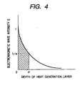
- the metal layer 1 may preferably have a thickness larger than the skin depth represented by the following equation, and particularly a thickness of 1 mm or more, and also preferably 200 ⁇ m or less, and particularly 100 ⁇ m or less.
- the metal layer 1 may preferably have a layer thickness of 100 ⁇ m or less, and particularly preferably 50 ⁇ m or less, and also preferably be 20 ⁇ m or more, in order to make its heat capacity small to improve quick-start performance.
- the electroformed nickel used in the present invention is usually in the form of crystals, but may partly be amorphous.
- the crystals may also preferably be not fine crystals in view of hardness and flexibility.
- the electroformed nickel used in the present invention which may preferably have a Vickers hardness of from 300 to 450, has sufficient heat resistance required as the fixing belt. Accordingly, the Vickers hardness may preferably be lowered at a rate of 20% or less when heated to 450°C.
- the electroformed nickel has sufficient heat resistance required as the fixing belt, it may also preferably have a recrystallization temperature of 450°C or above.
- the electroformed nickel may preferably have, at normal temperature, a tensile strength of from 700 to 1,500 MPa and an elongation of from 2 to 8%.
- the elastic layer 2 may be provided or not provided. Inasmuch as the elastic layer is provided, it covers the images to be heated, at the nip via the release layer 3 to ensure the conduction of heat, and also compensates the restoring force of the electroformed nickel belt to relax any fatigue caused by rotation and flexing. Also, inasmuch as the elastic layer is provided, it makes the release layer surface of the fixing belt better follow the unfixed toner image surface to enable heat to be conducted in a good efficiency.
- the fixing belt provided with the elastic layer 2 is particularly suited to the heat fixing of full-color or multi-color toner images where unfixed toners are laid on in a large quantity.
- materials for the elastic layer 2 those having good heat resistance and good thermal conductivity may be selected without any particular limitations.
- Such materials for the elastic layer 2 may preferably be silicone rubbers, fluorine rubbers, fluorosilicone rubbers and so forth, and silicone rubbers are particularly preferable.
- the silicone rubbers used in the elastic layer 2 may be exemplified by polydimethylsiloxane, polymethyltrifluoropropylsiloxane, polymethylvinylsiloxane, polyfluorpropylvinylsiloxane, polymethylpheylsiloxane, polyphenylvinylsiloxane, and copolymers of any of these polysiloxanes.
- the elastic layer 2 may also optionally be incorporated with a reinforcing filler such as dry-process silica or wet-process silica, calcium carbonate, quartz powder, zirconium silicate, clay (aluminum silicate), talc (hydrous magnesium silicate), alumina (aluminum oxide), iron red (iron oxide) or the like.
- a reinforcing filler such as dry-process silica or wet-process silica, calcium carbonate, quartz powder, zirconium silicate, clay (aluminum silicate), talc (hydrous magnesium silicate), alumina (aluminum oxide), iron red (iron oxide) or the like.
- the elastic layer 2 may preferably have a thickness of 10 ⁇ m or more, and particularly 50 ⁇ m or more, and preferably 1,000 ⁇ m or less, and particularly 500 ⁇ m or less, as good fixed-image quality can be achieved.
- solid images are formed over a large area on a recording medium P.
- the heating surface (release layer 3) can not follow up the unevenness of the recording medium or the unevenness of the toner layer, non-uniform heating may result, so that non-uniform glossiness appears on images between areas heat-conducted much and areas heat-conducted less.
- the elastic layer 2 may preferably have a hardness (JIS-A) of 60° or less, and particularly 45° or less, as any image glossiness non-uniformity can sufficiently be prevented and good fixed-image quality can be achieved.
- JIS-A hardness
- the elastic layer 2 may have a thermal conductivity ⁇ of 2.5 ⁇ 10 -3 W/cm ⁇ °C or more, and particularly 3.3 ⁇ 10 -3 W/cm ⁇ °C or more, and preferably 8.4 ⁇ 10 -3 W/cm ⁇ °C or less, and particularly 6.3 ⁇ 10 -3 W/cm ⁇ °C or less. If it has too small thermal conductivity X, it may have a high heat resistance to make the surface layer (release layer 3) of the fixing belt undergo slow temperature rise. If it has too large thermal conductivity ⁇ , it may have a high hardness or become worse in compression set.
- Such an elastic layer 2 may be formed by a known method as exemplified by a method in which a material such as liquid silicone rubber is coated on the metal layer 1 in a uniform thickness by blade coating or the like, followed by hardening by heating; a method in which a material such as liquid silicone rubber is injected into a mold, followed by hardening by curing; a method in which the like material is extruded, followed by hardening by curing; and a method in which the like material is injection-molded, followed by hardening by curing.
- Such materials for the release layer 3 may preferably be fluorine resins such as PFA (tetrafluoroethylene/perfluoroalkyl ether copolymer), PTFE (polytetrafluoroethylene) and FEP (tetrafluoroethylene/hexafluoropropylene copolymer), silicone resins, fluorosilicone rubbers, fluorine rubbers and silicone rubbers. PFA is particularly preferred.
- the release layer 3 may also optionally be incorporated with a conducting agent such as carbon black and tin oxide in an amount of 10% by weight or less based on the weight of the release layer 3.
- a conducting agent such as carbon black and tin oxide
- the release layer 3 may preferably have a thickness of 10 ⁇ m or more or 100 ⁇ m or less. If the release layer 3 is too thin, the layer may have poor releasability at some part because of coat non-uniformity of coating films, or may have insufficient durability. If on the other hand the release layer 3 is too thick, it may have a poor heat conduction and, especially in the case of a release layer of a resin type, it may have so high hardness as to make the elastic layer 2 no longer effective.
- Such a release layer 3 may be formed by a known method.
- a fluorine resin type one it may be formed by a method in which a coating material with fluorine resin powder dispersed therein is applied, followed by drying and baking, or by a method in which a material made previously into a tube is put on the elastic-layer or metal layer surface and bonded thereto.
- a rubber type one it may be formed by a method in which a liquid material is injected into a mold, followed by hardening by curing; a method in which the like material is extruded, followed by hardening by curing; and a method in which the like material is injection-molded, followed by hardening by curing.
- a method may also be used in which a tube having previously been treated with a primer on its inner surface and an electroformed nickel having previously been treated with a primer on its outer surface are fitted in a cylindrical mold, and then liquid silicone rubber is injected into a gap between the tube and the electroformed nickel belt, followed by hardening to cure and bond the rubber. This enables the elastic layer and the release layer to be simultaneously formed.
- the sliding layer 4 is not an essential component of the present invention, but may preferably be provided in order to achieve the reduction of drive torque applied when the image heat fixing assembly of the present invention is operated.
- the heat generated in the metal layer (heat generation layer) 1 can be insulated so as not to turn toward the inside of the fixing belt.
- the heat can be supplied to the recording medium P side in a good efficiency, and the power consumption can also be saved. It can also be intended to shorten the rise time.
- Such materials for the release layer 3 may preferably be polyimide resins or the like.
- the sliding layer 4 may optionally be incorporated with fluorine resin powder, graphite, molybdenum disulfide or the like as a sliding agent.
- the sliding layer 4 may preferably have a thickness of 5 ⁇ m or more, and particularly 10 ⁇ m or more, and preferably 100 ⁇ m or less, and particularly 60 ⁇ m or less. If the sliding layer 4 is too thin, the layer may have insufficient durability. If the sliding layer 4 is too thick, the fixing belt may have so large heat capacity as to result in a long rise time.
- Such a sliding layer 4 may be formed by a known method. For example, it may be formed by a method in which a liquid material is coated, followed by hardening by drying, or a method in which a material made previously into a tube is stuck.
- the image heat fixing assembly is described below.
- the image heat fixing assembly of the present invention has a fixing belt and a pair of pressure contact members which are mutually in pressure contact via the fixing belt.
- the inner surface of the fixing belt is slidable on one of the pressure contact members, and an image held on a recording medium are heat-fixed by the aid of the heat conducted from the fixing belt.
- the fixing belt used here is the above fixing belt of the present invention.
- an image heat fixing assembly having a magnetic-flux generation means which generates magnetic flux, where the fixing belt generates heat by the aid of the magnetic flux generated by this magnetic-flux generation means to heat-fix the image held on the recording medium; or an image heat fixing assembly in which the pressure contact member sliding on the fixing belt has a heating element, and the image held on the recording medium is heat-fixed by the aid of the heat conducted from the heating element.
- Fig. 5 is a cross-sectional diagrammatic view showing the main part of an image heat fixing assembly 100 of this embodiment.
- the image heat fixing assembly 100 is the assembly of an electromagnetic-induction heating system
- a fixing belt 10 is the above fixing belt of the present invention.
- the magnetic-flux generation means consists basically of a magnetic core 17 (17a to 17c) and an exciting coil 18.
- Fig. 6 is a diagrammatic view of the magnetic-field generation means of this image heat fixing assembly.
- the magnetic core 17 is a member having high permeability, and may preferably be those formed of materials used in cores of transformers, such as ferrite and Permalloy. In particular, it is preferable to use ferrite, which may cause less loss even at 100 kHz or more.
- a bundle of a plurality of small-gauge wires i.e., a bundled cable
- a conductor wire electric wire
- coatings having heat resistance may preferably be used, taking into account the heat conduction attributable to the heat generation of the fixing belt 10.
- coatings formed of polyimide resin or poly(amide-imide) resin may be used.
- a pressure may be applied from the outside of the exciting coil 18 to improve its closeness.
- An insulating member which also serves as a belt guide member, is provided between the magnetic-flux generation means and the fixing belt 10.
- materials for the insulating member those having excellent insulating properties and good heat resistance may be used.
- they may preferably include phenolic resins, fluorine resins, polyimide resins, polyamide resins, poly(amide-imide) resins, PEEK (polyether ether ketone) resins, PES (polyether sulfone) resins, PPS (polyphenylene sulfide) resins, PFA (tetrafluoroethylene/perfluoroalkyl ether copolymer) resins, PTFE (polytetrafluoroethylene) resins and FEP (tetrafluoroethylene/hexafluoropropylene copolymer) resins and LCP (liquid-crystal polyester).
- an excitation circuit 27 is connected to the exciting coil 18 at its electricity feeding terminals 18a and 18b.
- This excitation circuit 27 is so made that a high-frequency power of preferably from 20 kHz to 500 kHz can be produced by a switching power source.
- the exciting coil 18 generates alternating magnetic flux upon application of alternating current (high-frequency current).
- Fig. 7 diagrammatically illustrates how the alternating magnetic flux is generated.
- Magnetic flux C shows part of the alternating magnetic flux generated.
- the alternating magnetic flux (C) introduced into the magnetic core 17 causes the metal layer (electromagnetic-induction heat generation layer) 1 formed of the electroformed nickel, to produce eddy currents by electromagnetic induction.
- the eddy currents cause the electromagnetic-induction heat generation layer 1 to produce Joule heat (eddy current loss) in virtue of the specific resistance of the electromagnetic-induction heat generation layer 1.
- Heat generation quantity Q depends on the density of magnetic flux passing through the electromagnetic-induction heat generation layer 1, and shows such a distribution as shown in the graph of Fig. 7 . In the right drawing in Fig. 7 , the ordinate indicates by an angle ⁇ the position of the electromagnetic-induction heat generation layer.
- the abscissa indicates the heat generation quantity Q at the electromagnetic-induction heat generation layer 1 of the fixing belt 10.
- heat generation zones H are defined to be regions where the heat generation quantity Q is Q/e or more, assuming the maximum heat generation quantity as Q. This is the region where the heat generation quantity necessary for the fixing is obtained.
- the temperature at a fixing nip N ( Fig. 5 ) of this image heat fixing assembly is so temperature-controlled that a stated temperature can be maintained by controlling the feeding of electric current to the exciting coil 18 by means of a temperature control system having a temperature detection means (not shown).
- a temperature sensor 26 is a thermistor or the like which detects the temperature of the fixing belt 10. In this embodiment, it is so set that the temperature of the fixing nip N is controlled on the basis of the temperature information of the fixing belt 10, obtained by measurement with the temperature sensor 26.
- a pressure roller 30 as one of a pair of pressure contact members is constituted of a mandrel 30a and a heat-resistant elastic material layer 30b formed of silicone rubber, fluorine rubber, fluorine resin or the like with which the periphery of the mandrel is covered in a concentrically integral form by molding in a roller. It is so provided that both ends of the mandrel 30a are rotatively supported on bearings between plate metals of a chassis (not shown).
- a pressing rigid stay 22 and spring bearing members (not shown) on the chassis side of the assembly pressure springs (not shown) are respectively provided in a compressed state so that a press-down force acts on the pressing rigid stay 22.
- the bottom surface of a sliding plate 40 provided at the bottom surface of a belt guide member 16 and the top surface of the pressure roller 30 come into pressure contact holding the fixing belt 10 between them to form the fixing nip N in a stated width.
- materials for the belt guide member 16 it is preferable to use heat-resistant phenolic resin, LCP (liquid-crystal polyester) resin, PPS (polyphenylene sulfide) resin, PEEK (polyether ether ketone) resin or the like, having excellent heat resistance.
- the pressure roller 30 is rotatively driven by a drive means M in the anti-clockwise direction as shown by an arrow.
- a rotational force acts on the fixing belt 10.
- the fixing belt 10 is rotated along the outer surface of the belt guide member 16 in the clockwise direction as shown by an arrow and at a peripheral speed corresponding substantially to the rotational speed of the pressure roller 30 while sliding, at its inner surface, on the bottom surface of the sliding plate 40 at the fixing nip N.
- the pressure roller 30 is rotatively driven and, with its rotation, the fixing belt 10 is rotated, where the electromagnetic-induction heat generation of the fixing belt 10 is effected as described above, by supplying electricity to the exciting coil 18 from the excitation coil 27.
- a recording medium P transported from an image-forming means section (not shown) and on which an unfixed toner image t has been formed is guided to the fixing nip N between the fixing belt 10 and the pressure roller 30 with its image surface upside, i.e., facing the outer surface of the fixing belt 10.
- the image surface comes into close contact with the outer surface of the fixing belt 10, where the recording medium P is sandwiched and transported on through the fixing nip N together with the fixing belt 10.
- the unfixed toner image t is heated by the electromagnetic-induction heat generation of the fixing belt 10, and heat-fixed to the surface of the recording medium P.
- the recording medium P having passed through the fixing nip N is separated from the outer surface of the rotating fixing belt 10, and transported on until it is put out.
- the heat-fixed toner image on the recording medium becomes cool after it has passed through the fixing nip N, and turns into a permanent fixed image.
- the image heat fixing assembly is not provided with any oil application mechanism for preventing offset.
- an oil application mechanism may be provided when a toner not incorporated with any low-softening substance is used. Also when a toner incorporated with a low-softening substance is used, oil may be applied or the recording medium may be separated with cooling.
- the pressure roller 30 may also have, without limitation on its form, other forms such as a rotatively movable film type.
- a heating means of electromagnetic-induction heating or the like may also be provided on the pressure roller 30 side so that it can be so constructed as to be heated and temperature-controlled to the stated temperature.
- the fixing belt of the present invention may also be used in a fixing assembly of a belt heating system making use of a ceramic heater.
- Fig. 8 is a cross-sectional diagrammatic view showing an example of an image heat fixing assembly in this embodiment.
- the image heat fixing assembly is an assembly with a belt heating system making use of a ceramic heater, and a fixing belt 10 is the above fixing belt of the present invention.
- a belt guide 16 is a heat-resistant and heat-insulating belt guide.
- a ceramic heater 12 (12a to 12c) as a heating element is stationarily supported in the state it is inserted to a groove formed and provided at the bottom surface of the belt guide 16 at substantially the middle thereof in its lengthwise direction. Then, the fixing belt 10 of the present invention, which may be cylindrical or endless, is loosely externally fitted over the belt guide 16.
- a pressing rigid stay 22 is kept inserted to the inside of the belt guide 16.
- a pressure member 30 is, in this embodiment, an elastic pressure roller.
- This pressure roller 30 is constituted of a mandrel 30a and an elastic layer 30b of silicone rubber or the like provided on the mandrel so as to have a low hardness. It is so provided that both ends of the mandrel 30a are rotatively supported on bearings between chassis side plates (not shown) on the front and back sides.
- This elastic pressure roller 30 may further be provided on its periphery with a fluorine resin layer formed of PTFE (polytetrafluoroethylene), PFA (tetrafluoroethylene/ perfluoroalkyl ether copolymer), FEP (tetrafluoroethylene/hexafluoropropylene copolymer) or the like.
- a pressure means for forming a fixing nip N and a holding means at ends of the fixing belt may have the same construction as those in First Embodiment.
- the pressure roller 30 is rotatively driven by a drive means M in the anti-clockwise direction as shown by an arrow.
- a rotational force acts on the fixing belt 10.
- the fixing belt 10 is rotated along the outer surface of the belt guide member 16 in the clockwise direction as shown by an arrow and at a peripheral speed corresponding substantially to the rotational speed of the pressure roller 30 while sliding, at its inner surface, on the bottom surface of the ceramic heater 12 in close contact via a sliding member 40 at the fixing nip N (pressure roller drive system).
- the pressure roller 30 starts to be rotated in accordance with print start signals, and also the ceramic heater 12 starts to be heated up.
- a recording medium P holding a toner image t as a material to be heated is introduced into the fixing nip N between the fixing belt 10 and the pressure roller 30 with its toner-image-holding surface side on the fixing belt 10 side.
- the recording medium P comes into close contact with the bottom surface of the ceramic heater 12 via the fixing belt 10 and the sliding member 40, where it moves and passes through the fixing nip N together with the fixing belt 10.
- the heat of the ceramic heater 12 is imparted to the recording medium P via the fixing belt 10, so that the toner image t is heat-fixed to the surface of the recording medium P.
- the recording medium P having passed through the fixing nip N is separated from the outer surface of the rotating fixing belt 10 and transported on.
- the ceramic heater 12 as a heating element is an oblong linear heating element with a low heat capacity whose lengthwise direction is at right angles to the direction of movement of the fixing belt 10 and recording medium P. It is basically constituted of a heater substrate 12a made of aluminum nitride or the like, a heat generation layer 12b provided on the surface of this heater substrate 12a in its lengthwise direction, which is a heat generation layer 12b provided by, e.g., applying a electrically resistant material such as Ag/Pd (silver/palladium) by screen printing or the like in a thickness of about 10 ⁇ m and a width of from 1 to 5 mm, and further provided thereon a protective layer 12c formed of glass, fluorine resin or the like.
- the ceramic heater 12 used is by no means limited to the one described above.
- the heat generation layer 12b of the ceramic heater 12 upon electrification at both ends of the heat generation layer 12b of the ceramic heater 12, the heat generation layer 12b generates heat, and the temperature of the heater 12 rises quickly.
- This heater temperature is detected by a temperature sensor (not shown), and the electrification to the heat generation layer 12b is controlled by a control circuit (not shown) so that the heater temperature can be maintained at the desired temperature.
- the ceramic heater 12 is temperature-controlled.
- the ceramic heater 12 is stationarily supported in the state it is inserted with its protective layer 12c side downward, to the groove formed and provided at the bottom surface of the belt guide 16 at substantially the middle thereof in its lengthwise direction.
- the surface of the sliding member 40 of the ceramic heater 12 and the inner surface of the fixing belt 10 slide coming in contact with each other.
- a ferromagnetic-material metal plate such as an iron plate may be provided, and this ferromagnetic-material metal plate may be used as a heater to generate heat by the electromagnetic induction used in First Embodiment.
- the pressure roller 30 may also have, without limitation on the form of a roller, other forms such as a rotatively movable film type.
- a heating means of electromagnetic-induction heating or the like may also be provided on the pressure roller 30 side so that it can be so constructed as to be heated and temperature-controlled to the stated temperature.
- the construction of the image heat fixing assembly is by no means limited to the system driven by the pressure roller as in the above embodiments.
- the assembly may be so constructed that the fixing belt 10 of the present invention is put and stretched over a belt guide 16, a drive roller 31 and a tension roller 32, where the bottom surface of the belt guide 16 and a pressure roller 30 as a pressure contact member are brought into pressure contact interposing the fixing belt 10 between them to form a fixing nip N and the fixing belt 10 is rotatively driven by means of the drive roller 31.
- the pressure roller 30 is a follower rotating roller.
- the pressure roller 30 may also have, without limitation on the form of a roller, other forms such as a rotatively movable film type.
- a heating means of electromagnetic-induction heating or the like may also be provided on the pressure roller 30 side so that it can be so constructed as to be heated and temperature-controlled to the stated temperature.
- the image heat fixing assembly of the present invention is an image heating assembly, and is not limited to the use as the image heat fixing assembly. It may also be used as an image heating assembly with which a recording medium holding an image is heated to modify its surface properties such as glossiness, or an image heating assembly for provisional fixing. Besides, it may widely be used as a heat drying assembly for materials to be heated, a heat lamination assembly and so forth, which are means and assemblies with which materials to be heated are heat-treated.
- electroformed-nickel endless belts 34 mm in inner diameter and 50 ⁇ m in thickness each were selected which were produced under conditions shown in Table 1 and in the following way.
- a silicone rubber layer 300 ⁇ m thick as the elastic layer 2 and a PFA tube 30 ⁇ m thick as the release layer 3 were respectively overlaid via a primer to the surface of each of the electroformed-nickel endless belts, and a polyimide resin layer 15 ⁇ m in thickness as the sliding layer 4 was further overlaid, as shown in Fig. 2 .
- various fixing belts of Examples. 1 to 8 and Comparative Examples 1 to 8 were produced.
- an aqueous solution bath comprised of 450 g/L of nickel sulfamate tetrahydrate, 10 g/L of nickel chloride and 40 g/L of boric acid was prepared, and then a pit preventive agent was added in a necessary amount, followed by addition of saccharin as a first brightener and 2-butine-1,4-diol as a second brightener in the amounts shown in Table 1.
- the resulting bath was subjected to electrolytic purification at a low current density while being filtered in a container filled with activated carbon.
- nickel electroforming was carried out at electroforming-bath temperature and various cathode current densities and stirring-based bath flow velocities in the vicinity of the mold (flow velocities of electroforming baths in respect to the mold surface) as shown in the following Table 1, to form films of electroformed nickel of 34 mm in inner diameter and 50 ⁇ m in thickness each. Then, each electroformed nickel was removed from the mold to obtain the metal layer 1.
- Table 1 Brightener Process conditions Saccharin (g/L) Butinediol (g/L) Bath temp.
- Example 1 0.03 0.3 53 0.75 4
- Example 2 0.03 0.5 53 1.5 4
- Example 3 0.07 0.8 53 0.75 15
- Example 4 0.03 0.3 53 2 10
- Example 5 0.03 0.5 53 2.5 4
- Example 6 0.04 0.4 53 1.5 6
- Example 7 0.07 0.8 53 1.5 15
- Example 8 0.04 0.6 53 1.5 10 Comparative Example 1 0.005 0.05 53 4 35 Comparative Example 2 0.12 0.1 53 0.5 10 Comparative Example 3 0.02 1.2 53 1.5 4 Comparative Example 4 0.08 1.0 53 6 10 Comparative Example 5 1.0 1.5 53 1.5 10 Comparative Example 6 0.06 0.3 53 0.1 0.5 Comparative Example 7 0.04 0.5 53 6 40 Comparative Example 8 0.04 0.5 53 0.1 40
- the size of crystallites of the electroformed nickel obtained was measured with an X-ray diffraction apparatus (RINT2100/PC, manufactured by Rigaku K.K.) and an analytical software JADE, on Ni (111) diffraction plane by using characteristic X-ray Cu-K (wavelength: 1.5405620 A), and was found by including in the Hall's equation the results of measurement of the extent (integral width) of the diffraction profile.
- This Hall method is a method in which the extent of diffraction lines by the size and lattice strain of crystallites is extracted from the extent (integral width) of the diffraction profile to calculate the size and lattice strain of crystallites. That is, in the present invention, even the lattice strain was taken into account, and using the true extent (integral width) of the diffraction profile by the crystallites in the (111)-direction, the sizes of crystallites were determined.
- the sectional crystal texture of the electroformed nickel was observed and evaluated in the following way.
- 10A and 10B are SEM photographs of the sectional crystal texture of the electroformed nickel in Example 4. From the photographs, 50 pieces of crystal texture was picked up at random, and the length b and breadth a of crystal grains were measured using an image-analyzing software IMAGE-PRO PLUS and an image analyzer to determine the average value of the shape factor (b/a) and the average size (b + a)/2 of crystallites.
- the image analyzer was used to determine the regularity of the sectional crystal texture of electroformed nickel (as scattering of angles with respect to the direction of growth in length of 10 crystal grains which are continuously contiguous, in respect to individual crystal grains at three spots picked up at random). As the result, it was ascertained that, in the sectional crystal texture, grainy texture has a given regularity uniformly in the direction of growth or in the direction vertical to the mold surface.
- the crystal texture of fine crystals was also observed using a 2010F field emission type transmission electron microscope (FE-TEM) manufactured by Nippon Denshi K.K. to confirm the presence of twin texture having small-inclination grain boundaries present in the crystal texture according to the present invention.
- the twins of Examples were all in a width of 0.05 ⁇ m.
- Comparative Example 3 stated electroformed-nickel endless belt were obtained.
- Comparative Example 3 in which the butinediol was added in an amount of 1.2 g/L, the nickel film was released from the mold during the crystal growth of nickel. This is due to the fact that the nickel having been formed in a film has an excessive tensile stress.
- the electroformed-nickel endless belts (metal layers) produced as described above were each previously coated with a primer (DY35-051, available from Dow Corning Toray Silicone Co., Ltd.) by spraying, followed by drying at 150°C for 30 minutes to form a primer layer of 5 ⁇ m in thickness.
- a primer DY35-051, available from Dow Corning Toray Silicone Co., Ltd.
- a primer layer was formed on the inner surface of a PFA tube in the same way. Then the resulting PFA tube was, together with each of the above metal layers, fitted to a cylindrical mold having substantially the same inner diameter as the outer diameter of the PFA tube, so as to be on the same axis.
- a liquid silicone rubber (DY32-561A/B, available from Dow Corning Toray Silicone Co., Ltd.) was injected into the space between the tube and the metal layer, followed by heating in a hot-air circulating furnace at 200°C for 30 minutes.
- a polyimide varnish (U-VARNISH S, available from Ube Industries) was applied, followed by curing by drying at 210°C for 1 hour in a hot-air circulation furnace to form a polyimide resin layer of 15 ⁇ m in thickness as the sliding layer 4.
- the pressure roller was pressed against the fixing belt at a stated pressure to make the fixing belt rotate following to the pressure roller.
- a rubber roller of 30 mm in outer diameter was used which had a silicone layer of 3 mm in thickness covered with a PFA tube of 30 ⁇ m in thickness.
- the pressure applied was 200 N
- the fixing nip N was 8 mm ⁇ 230 mm
- the surface velocity of the fixing belt was 100 mm/sec.
- the fixing belts were each subjected to the above blank-rotation running test. The time by which any cracking or break of the belt occurred was regarded as running time.
- Example 1 Crystallite size (nm) Crystal-grain breadth a ( ⁇ m) Crystal-grain length b ( ⁇ m) Average size (a+b)/2 ( ⁇ m) Shape factor (b/a) Area percentage (%) Scattering of length angles (°) (shape) Running time (hrs)
- Example 1 70 0.6 0.7 0.65 1.17 90 14 (grainy) 600
- Example 2 80 0.65 0.95 0.8 1.26 95 12(grainy) 600
- Example 3 85 0.6 0.75 0.675 1.25 93 11(grainy) 500
- Example 4 90 0.9 1.1 1.0 1.22 93 8(grainy) 800
- Example 5 85 0.5 0.63 0.565 1.26 91 15(grainy) 650
- Example 6 90 0.91 1.15 1.03 1.26 90 11(grainy) 700
- Example 7 95 1.05 1.21 1.13 1.15 89 14(grainy) 530
- Example 8 100 0.85 1.05 0.95 1.24 90 13(grainy) 540 Comparative
- the running time in all cases was more than 500 hours when the electroformed-nickel fixing belts of the present invention (Examples 1 to 8) were used, in which the crystallites in the crystal texture of the electroformed nickel have an average size of 0.05 ⁇ m or more and 0.2 ⁇ m or less, in the sectional crystal texture the crystal grains have an average size [(b + a)/2] of 0.1 ⁇ m or more and 3 ⁇ m or less, the area percentage occupied by texture in which the crystal shape factor (b/a) is 2 or less is 50% or more, and the scattering of angles with respect to the direction of growth in length of 10 crystal grains which are continuously contiguous is 30° or less.
- the fixing assemblies used in Experiment 1 were each further mounted on a full-color laser beam printer (LBP) LASER SHOT "LBP-2040", manufactured by CANON INC., and images were reproduced to conduct a running test. Conditions were so set that the pressure applied was 200 N, the fixing nip N was 8 mm x 230 mm and the process speed was 100 mm/sec. In those making use of the fixing belts of Examples 1 to 8, images were reproduced on 100,000 sheets without any troubles, and the running test was completed. On the other hand, in those making use of the fixing belt of Comparative Example 1 and the fixing belts of Comparative Examples 2 and 4 to 8, the paper feed came impossible because of break of the fixing belts on 10,000th sheet and 30,000th sheet, respectively.
- LBP full-color laser beam printer
- the fixing belts of Examples 1 to 8 were each set in the assembly (assembly 100) of a belt heating system making use of a ceramic heater 12 as a heating element as shown in Fig. 8 , and were subjected to the blank-rotation running test. As a result, it was able to confirm sufficient heat resistance and durability.
Landscapes
- Physics & Mathematics (AREA)
- General Physics & Mathematics (AREA)
- Fixing For Electrophotography (AREA)
Claims (3)
- Verfahren zur Herstellung eines Fixierungsbands (10, 10'), das ein Galvanogeformtes Nickelendlosband, dessen Dicke von 20 µm bis 200 µm ist, und eine darauf gebildete Trennschicht (3, 3') umfasst;
der Prozess umfasst einen Schritt der Galvanoformung des Nickelendlosbands auf einer Form in einem Galvanoformungsbad bei einer Stromdichte von 1A/dm2 bis 30A/dm2, und einer Strömungsgeschwindigkeit von 0,25m/s bis 5m/s bezüglich der Oberfläche der Form
wobei das Verfahren dadurch gekennzeichnet ist, dass
das Galvanoformungsbad Saccharin in einer Menge von 0,005g/L bis 0,1g/L und Butindiol in einer Menge von 0,05g/L bis 1g/L enthält und dass
das Nickelendlosband in seinem Kristallaufbau Kristallite mit einer durchschnittlichen Größe von 0,05 µm oder mehr und 0,2 µm oder weniger aufweist, wobei die durchschnittliche Größe mit einer Röntgenstrahlbeugungsvorrichtung auf einer Ni (111) Beugungsebene unter Verwendung von Cu-K Röntgenstrahlen gemessen ist. - Verfahren nach Anspruch 1, wobei das Nickelendlosband in seinem Querschnittskristallaufbau Kristallkörner aufweist, deren durchschnittliche Größe [(b+a)/2] von 0,1 µm bis 3 µm ist, wobei eine Länge und eine Breite eines Kristallkorns jeweils "b" beziehungsweise "a" dargestellt sind, die Breite "a" eine maximale Länge in der Richtung senkrecht zu der Länge "b" ist, und ein Flächenprozentsatz, der durch den Aufbau besetzt wird, in welchem der durch (b/a) dargestellte Kristallformfaktor 2 oder weniger ist, 50% oder mehr ist.
- Verfahren nach Anspruch 1, wobei der Kristallaufbau in dem Querschnittskristallaufbau des galvanogeformten Nickels Kornanordnungen mit Regelmäßigkeit bildet.
Applications Claiming Priority (2)
| Application Number | Priority Date | Filing Date | Title |
|---|---|---|---|
| JP2002170593 | 2002-06-11 | ||
| JP2002170593 | 2002-06-11 |
Publications (2)
| Publication Number | Publication Date |
|---|---|
| EP1378802A1 EP1378802A1 (de) | 2004-01-07 |
| EP1378802B1 true EP1378802B1 (de) | 2015-08-12 |
Family
ID=29706882
Family Applications (1)
| Application Number | Title | Priority Date | Filing Date |
|---|---|---|---|
| EP03013037.1A Expired - Lifetime EP1378802B1 (de) | 2002-06-11 | 2003-06-10 | Fixierband und Wärmefixiereinrichtung hiermit für Bilder |
Country Status (2)
| Country | Link |
|---|---|
| US (1) | US6782230B2 (de) |
| EP (1) | EP1378802B1 (de) |
Families Citing this family (27)
| Publication number | Priority date | Publication date | Assignee | Title |
|---|---|---|---|---|
| US7215916B2 (en) * | 2003-11-12 | 2007-05-08 | Canon Kabushiki Kaisha | Endless metal belt, fixing belt and heat fixing device |
| WO2005054960A1 (ja) * | 2003-12-02 | 2005-06-16 | Canon Denshi Kabushiki Kaisha | 金属ベルト、定着ベルト及び加熱定着装置 |
| JP4444648B2 (ja) * | 2003-12-25 | 2010-03-31 | シンジーテック株式会社 | 定着ベルト |
| JP4537215B2 (ja) * | 2004-02-03 | 2010-09-01 | キヤノン株式会社 | 像加熱装置 |
| US20060067754A1 (en) * | 2004-09-29 | 2006-03-30 | Gilmore James D | Fuser assembly with six layer endless belt in an electrophotographic imaging device |
| EP1688927A3 (de) * | 2005-02-08 | 2007-08-08 | FUJIFILM Corporation | Magnetische Übertragungsmasterplatte, Herstellungsverfahren und magnetisches Übertragungsverfahren |
| CN100387756C (zh) * | 2005-04-07 | 2008-05-14 | 上海交通大学 | 提高叠层微器件镍或镍合金铸层间结合强度的方法 |
| JP4827080B2 (ja) * | 2005-12-19 | 2011-11-30 | 株式会社リコー | 定着装置及び画像形成装置 |
| US7437110B2 (en) * | 2006-02-13 | 2008-10-14 | Kyocera Mita Corportation | Fixing device |
| KR101511499B1 (ko) * | 2007-10-24 | 2015-04-16 | 삼성전자주식회사 | 정착장치 및 이를 구비한 화상형성장치 |
| US8369719B2 (en) * | 2008-01-04 | 2013-02-05 | Samsung Electronics Co., Ltd. | Image forming apparatus, fusing device thereof and method of controlling fusing device |
| US8014714B2 (en) * | 2008-08-28 | 2011-09-06 | Xerox Corporation | Fusers, printing apparatuses and methods of fusing toner on media |
| US7848672B2 (en) * | 2008-10-02 | 2010-12-07 | Xerox Corporation | Fusers including heater for pre-heating fuser belt, printing apparatuses and methods of fusing toner on media with pre-heating of fuser belt |
| US8139992B2 (en) * | 2009-04-07 | 2012-03-20 | Xerox Corporation | Apparatuses useful for printing and methods of treating marking material on media |
| US8107871B2 (en) * | 2009-04-29 | 2012-01-31 | Xerox Corporation | Apparatuses useful for printing and methods of treating marking material on media |
| JP5419533B2 (ja) * | 2009-04-30 | 2014-02-19 | キヤノン株式会社 | 画像形成装置 |
| US8280286B2 (en) | 2009-06-24 | 2012-10-02 | Xerox Corporation | Apparatuses useful in printing and methods of fixing marking material on media |
| US8204417B2 (en) * | 2009-07-30 | 2012-06-19 | Xerox Corporation | Apparatuses useful in printing, fixing devices and methods of stripping media from surfaces in apparatuses useful in printing |
| JP2011248187A (ja) * | 2010-05-28 | 2011-12-08 | Konica Minolta Business Technologies Inc | 定着装置および画像形成装置 |
| JP6202918B2 (ja) * | 2012-07-27 | 2017-09-27 | キヤノン株式会社 | 電子写真用部材、電子写真用部材の製造方法、定着装置および電子写真画像形成装置 |
| JP2014194522A (ja) * | 2013-02-26 | 2014-10-09 | Ricoh Co Ltd | 定着ベルト用基材、定着ベルト、定着装置、および、画像形成装置 |
| JP2014194445A (ja) * | 2013-03-28 | 2014-10-09 | Brother Ind Ltd | 画像形成装置および熱定着装置 |
| US10384441B2 (en) * | 2016-07-28 | 2019-08-20 | Xerox Corporation | Fluorosilicone composite and formulation process for imaging plate |
| JP7293828B2 (ja) | 2019-04-11 | 2023-06-20 | 富士フイルムビジネスイノベーション株式会社 | 定着部材、定着装置、及び画像形成装置 |
| JP7293829B2 (ja) | 2019-04-11 | 2023-06-20 | 富士フイルムビジネスイノベーション株式会社 | 定着部材、定着装置、及び画像形成装置 |
| JP7354719B2 (ja) | 2019-09-24 | 2023-10-03 | 富士フイルムビジネスイノベーション株式会社 | 定着部材、定着装置、及び画像形成装置 |
| JP7749422B2 (ja) | 2021-11-22 | 2025-10-06 | キヤノン株式会社 | シート給送装置及び画像形成装置 |
Family Cites Families (21)
| Publication number | Priority date | Publication date | Assignee | Title |
|---|---|---|---|---|
| US5027160A (en) | 1988-12-08 | 1991-06-25 | Canon Kabushiki Kaisha | Image fixing apparatus with movable film and means for controlling film position |
| JP3352134B2 (ja) | 1993-01-21 | 2002-12-03 | 住友電気工業株式会社 | 定着用ベルト |
| JPH0713448A (ja) | 1993-06-29 | 1995-01-17 | Hitachi Ltd | 定着装置 |
| JP3311111B2 (ja) | 1993-10-18 | 2002-08-05 | キヤノン株式会社 | 像加熱装置及び像加熱用回転体 |
| US5608508A (en) | 1994-03-25 | 1997-03-04 | Canon Kabushiki Kaisha | Rotatable member for fixing in which inorganic filler is contained in silicone rubber, and fixing device having the same |
| US5753348A (en) | 1995-05-31 | 1998-05-19 | Canon Kabushiki Kaisha | Fluororesin tube-covered fixing roller, and image formation apparatus |
| JP2706432B2 (ja) * | 1995-07-24 | 1998-01-28 | 日東工業株式会社 | 電子写真装置用定着ベルト及び定着装置 |
| JPH0944014A (ja) * | 1995-08-03 | 1997-02-14 | Canon Inc | 加熱用フィルム、加熱加圧部材、加熱装置及び画像形成装置 |
| US5939337A (en) * | 1995-08-03 | 1999-08-17 | Canon Kabushiki Kaisha | Toner fixation film and toner fixation apparatus using it |
| US5765086A (en) | 1995-10-09 | 1998-06-09 | Canon Kabushiki Kaisha | Heat fixing belt with conductive aluminum layer toner release layer and elastic layer disposed therebetween |
| JP3472043B2 (ja) | 1996-08-01 | 2003-12-02 | キヤノン株式会社 | 像加熱装置および画像形成装置 |
| US5950061A (en) | 1996-11-29 | 1999-09-07 | Canon Kabushiki Kaisha | Fixing member having an inner elastic layer with a surface roughness |
| US6377777B1 (en) | 1999-02-19 | 2002-04-23 | Canon Kabushiki Kaisha | Fluorine-containing resin-coated pressure roller and heat-fixing device |
| US6321062B1 (en) | 1999-03-09 | 2001-11-20 | Canon Kabushiki Kaisha | Fixing-unit roller making use of composite material, process for its production, and fixing assembly employing the roller |
| JP2001215820A (ja) * | 2000-02-03 | 2001-08-10 | Sumitomo Electric Fine Polymer Inc | 樹脂被覆ベルト及びその製造方法 |
| JP4042362B2 (ja) * | 2000-08-11 | 2008-02-06 | 住友金属工業株式会社 | Ni基合金製品とその製造方法 |
| JP4707821B2 (ja) | 2000-11-10 | 2011-06-22 | 住友電工ファインポリマー株式会社 | 定着ベルト及びその製造方法 |
| US6564033B2 (en) | 2000-12-12 | 2003-05-13 | Canon Kabushiki Kaisha | Fixing belt and image heating and fixing apparatus |
| JP2002206188A (ja) * | 2001-01-09 | 2002-07-26 | Sumitomo Electric Fine Polymer Inc | 電鋳ニッケルベルト、被覆ニッケルベルト、及び被覆ニッケルベルトの製造方法 |
| JP4717292B2 (ja) | 2001-09-14 | 2011-07-06 | キヤノン株式会社 | 画像形成装置 |
| JP2003208055A (ja) | 2001-11-08 | 2003-07-25 | Canon Inc | 像加熱装置及びこの装置に用いられる弾性ローラ |
-
2003
- 2003-06-10 EP EP03013037.1A patent/EP1378802B1/de not_active Expired - Lifetime
- 2003-06-10 US US10/457,360 patent/US6782230B2/en not_active Expired - Lifetime
Also Published As
| Publication number | Publication date |
|---|---|
| US20030228179A1 (en) | 2003-12-11 |
| EP1378802A1 (de) | 2004-01-07 |
| US6782230B2 (en) | 2004-08-24 |
Similar Documents
| Publication | Publication Date | Title |
|---|---|---|
| EP1378802B1 (de) | Fixierband und Wärmefixiereinrichtung hiermit für Bilder | |
| EP1837715B1 (de) | Metallenes Endlosband, Fixierband und diese verwendende Wärmefixierungsanordnung | |
| US20070147915A1 (en) | Endless metal belt, fixing belt and heat fixing device | |
| US6564033B2 (en) | Fixing belt and image heating and fixing apparatus | |
| JP3472286B2 (ja) | 定着ベルトおよび像加熱定着装置 | |
| CN100419592C (zh) | 金属带、定影带及其加热定影装置 | |
| JP5099749B2 (ja) | 無端状金属ベルト及びそれを用いた定着ベルト、加熱定着装置 | |
| US7433642B2 (en) | Fixing member, fixing device and image forming device with metal layers having different specific resistances | |
| JP2004068148A (ja) | 定着ベルトおよび像加熱定着装置 | |
| JP2012168218A (ja) | 金属ベルト | |
| JP2005165291A (ja) | 無端状金属ベルト、定着ベルトおよび加熱定着装置 | |
| JP4344158B2 (ja) | 定着ベルトおよび像加熱定着装置 | |
| JP3905053B2 (ja) | 定着ベルト | |
| JP2008256839A (ja) | 定着ベルト、定着装置、及び画像形成装置 | |
| JP4344189B2 (ja) | 定着ベルト | |
| US11067928B2 (en) | Fixing member, fixing unit, and image forming apparatus | |
| JP5438437B2 (ja) | 定着ベルト | |
| JP2005241955A (ja) | 定着ベルト部材 |
Legal Events
| Date | Code | Title | Description |
|---|---|---|---|
| PUAI | Public reference made under article 153(3) epc to a published international application that has entered the european phase |
Free format text: ORIGINAL CODE: 0009012 |
|
| AK | Designated contracting states |
Kind code of ref document: A1 Designated state(s): AT BE BG CH CY CZ DE DK EE ES FI FR GB GR HU IE IT LI LU MC NL PT RO SE SI SK TR |
|
| AX | Request for extension of the european patent |
Extension state: AL LT LV MK |
|
| 17P | Request for examination filed |
Effective date: 20040518 |
|
| AKX | Designation fees paid |
Designated state(s): DE FR GB IT |
|
| 17Q | First examination report despatched |
Effective date: 20071113 |
|
| RAP1 | Party data changed (applicant data changed or rights of an application transferred) |
Owner name: CANON KABUSHIKI KAISHA |
|
| GRAP | Despatch of communication of intention to grant a patent |
Free format text: ORIGINAL CODE: EPIDOSNIGR1 |
|
| INTG | Intention to grant announced |
Effective date: 20141007 |
|
| RIN1 | Information on inventor provided before grant (corrected) |
Inventor name: SASAKI, KOJI Inventor name: KISHINO, KAZUO Inventor name: YAOMIN, ZHOU Inventor name: SUZUKI, MASAHIRO Inventor name: YANO, HIDEYUKI |
|
| GRAJ | Information related to disapproval of communication of intention to grant by the applicant or resumption of examination proceedings by the epo deleted |
Free format text: ORIGINAL CODE: EPIDOSDIGR1 |
|
| GRAP | Despatch of communication of intention to grant a patent |
Free format text: ORIGINAL CODE: EPIDOSNIGR1 |
|
| GRAP | Despatch of communication of intention to grant a patent |
Free format text: ORIGINAL CODE: EPIDOSNIGR1 |
|
| RAP1 | Party data changed (applicant data changed or rights of an application transferred) |
Owner name: CANON KABUSHIKI KAISHA |
|
| RIN1 | Information on inventor provided before grant (corrected) |
Inventor name: SUZUKI, MASAHIRO Inventor name: YAOMIN, ZHOU Inventor name: SASAKI, KOJI Inventor name: YANO, HIDEYUKI Inventor name: KISHINO, KAZUO |
|
| INTG | Intention to grant announced |
Effective date: 20150304 |
|
| GRAS | Grant fee paid |
Free format text: ORIGINAL CODE: EPIDOSNIGR3 |
|
| GRAA | (expected) grant |
Free format text: ORIGINAL CODE: 0009210 |
|
| AK | Designated contracting states |
Kind code of ref document: B1 Designated state(s): DE FR GB IT |
|
| REG | Reference to a national code |
Ref country code: GB Ref legal event code: FG4D |
|
| REG | Reference to a national code |
Ref country code: DE Ref legal event code: R096 Ref document number: 60347898 Country of ref document: DE |
|
| PG25 | Lapsed in a contracting state [announced via postgrant information from national office to epo] |
Ref country code: IT Free format text: LAPSE BECAUSE OF FAILURE TO SUBMIT A TRANSLATION OF THE DESCRIPTION OR TO PAY THE FEE WITHIN THE PRESCRIBED TIME-LIMIT Effective date: 20150812 |
|
| REG | Reference to a national code |
Ref country code: DE Ref legal event code: R097 Ref document number: 60347898 Country of ref document: DE |
|
| PLBE | No opposition filed within time limit |
Free format text: ORIGINAL CODE: 0009261 |
|
| STAA | Information on the status of an ep patent application or granted ep patent |
Free format text: STATUS: NO OPPOSITION FILED WITHIN TIME LIMIT |
|
| 26N | No opposition filed |
Effective date: 20160513 |
|
| GBPC | Gb: european patent ceased through non-payment of renewal fee |
Effective date: 20160610 |
|
| REG | Reference to a national code |
Ref country code: FR Ref legal event code: ST Effective date: 20170228 |
|
| PG25 | Lapsed in a contracting state [announced via postgrant information from national office to epo] |
Ref country code: FR Free format text: LAPSE BECAUSE OF NON-PAYMENT OF DUE FEES Effective date: 20160630 |
|
| PG25 | Lapsed in a contracting state [announced via postgrant information from national office to epo] |
Ref country code: GB Free format text: LAPSE BECAUSE OF NON-PAYMENT OF DUE FEES Effective date: 20160610 |
|
| PGFP | Annual fee paid to national office [announced via postgrant information from national office to epo] |
Ref country code: DE Payment date: 20170630 Year of fee payment: 15 |
|
| REG | Reference to a national code |
Ref country code: DE Ref legal event code: R119 Ref document number: 60347898 Country of ref document: DE |
|
| PG25 | Lapsed in a contracting state [announced via postgrant information from national office to epo] |
Ref country code: DE Free format text: LAPSE BECAUSE OF NON-PAYMENT OF DUE FEES Effective date: 20190101 |