EP1379000B1 - Verfahren und vorrichtung zur signal-kodierung/ dekodierung - Google Patents
Verfahren und vorrichtung zur signal-kodierung/ dekodierung Download PDFInfo
- Publication number
- EP1379000B1 EP1379000B1 EP20020714541 EP02714541A EP1379000B1 EP 1379000 B1 EP1379000 B1 EP 1379000B1 EP 20020714541 EP20020714541 EP 20020714541 EP 02714541 A EP02714541 A EP 02714541A EP 1379000 B1 EP1379000 B1 EP 1379000B1
- Authority
- EP
- European Patent Office
- Prior art keywords
- transformation
- signal
- base
- bases
- encoded
- Prior art date
- Legal status (The legal status is an assumption and is not a legal conclusion. Google has not performed a legal analysis and makes no representation as to the accuracy of the status listed.)
- Expired - Lifetime
Links
Images








Classifications
-
- H—ELECTRICITY
- H04—ELECTRIC COMMUNICATION TECHNIQUE
- H04N—PICTORIAL COMMUNICATION, e.g. TELEVISION
- H04N19/00—Methods or arrangements for coding, decoding, compressing or decompressing digital video signals
- H04N19/60—Methods or arrangements for coding, decoding, compressing or decompressing digital video signals using transform coding
-
- H—ELECTRICITY
- H04—ELECTRIC COMMUNICATION TECHNIQUE
- H04N—PICTORIAL COMMUNICATION, e.g. TELEVISION
- H04N19/00—Methods or arrangements for coding, decoding, compressing or decompressing digital video signals
- H04N19/10—Methods or arrangements for coding, decoding, compressing or decompressing digital video signals using adaptive coding
- H04N19/134—Methods or arrangements for coding, decoding, compressing or decompressing digital video signals using adaptive coding characterised by the element, parameter or criterion affecting or controlling the adaptive coding
- H04N19/136—Incoming video signal characteristics or properties
- H04N19/14—Coding unit complexity, e.g. amount of activity or edge presence estimation
-
- H—ELECTRICITY
- H04—ELECTRIC COMMUNICATION TECHNIQUE
- H04N—PICTORIAL COMMUNICATION, e.g. TELEVISION
- H04N19/00—Methods or arrangements for coding, decoding, compressing or decompressing digital video signals
- H04N19/10—Methods or arrangements for coding, decoding, compressing or decompressing digital video signals using adaptive coding
- H04N19/102—Methods or arrangements for coding, decoding, compressing or decompressing digital video signals using adaptive coding characterised by the element, parameter or selection affected or controlled by the adaptive coding
- H04N19/12—Selection from among a plurality of transforms or standards, e.g. selection between discrete cosine transform [DCT] and sub-band transform or selection between H.263 and H.264
-
- H—ELECTRICITY
- H04—ELECTRIC COMMUNICATION TECHNIQUE
- H04N—PICTORIAL COMMUNICATION, e.g. TELEVISION
- H04N19/00—Methods or arrangements for coding, decoding, compressing or decompressing digital video signals
- H04N19/10—Methods or arrangements for coding, decoding, compressing or decompressing digital video signals using adaptive coding
- H04N19/169—Methods or arrangements for coding, decoding, compressing or decompressing digital video signals using adaptive coding characterised by the coding unit, i.e. the structural portion or semantic portion of the video signal being the object or the subject of the adaptive coding
- H04N19/17—Methods or arrangements for coding, decoding, compressing or decompressing digital video signals using adaptive coding characterised by the coding unit, i.e. the structural portion or semantic portion of the video signal being the object or the subject of the adaptive coding the unit being an image region, e.g. an object
- H04N19/176—Methods or arrangements for coding, decoding, compressing or decompressing digital video signals using adaptive coding characterised by the coding unit, i.e. the structural portion or semantic portion of the video signal being the object or the subject of the adaptive coding the unit being an image region, e.g. an object the region being a block, e.g. a macroblock
-
- H—ELECTRICITY
- H04—ELECTRIC COMMUNICATION TECHNIQUE
- H04N—PICTORIAL COMMUNICATION, e.g. TELEVISION
- H04N19/00—Methods or arrangements for coding, decoding, compressing or decompressing digital video signals
- H04N19/10—Methods or arrangements for coding, decoding, compressing or decompressing digital video signals using adaptive coding
- H04N19/189—Methods or arrangements for coding, decoding, compressing or decompressing digital video signals using adaptive coding characterised by the adaptation method, adaptation tool or adaptation type used for the adaptive coding
- H04N19/196—Methods or arrangements for coding, decoding, compressing or decompressing digital video signals using adaptive coding characterised by the adaptation method, adaptation tool or adaptation type used for the adaptive coding being specially adapted for the computation of encoding parameters, e.g. by averaging previously computed encoding parameters
-
- H—ELECTRICITY
- H04—ELECTRIC COMMUNICATION TECHNIQUE
- H04N—PICTORIAL COMMUNICATION, e.g. TELEVISION
- H04N19/00—Methods or arrangements for coding, decoding, compressing or decompressing digital video signals
- H04N19/46—Embedding additional information in the video signal during the compression process
-
- H—ELECTRICITY
- H04—ELECTRIC COMMUNICATION TECHNIQUE
- H04N—PICTORIAL COMMUNICATION, e.g. TELEVISION
- H04N19/00—Methods or arrangements for coding, decoding, compressing or decompressing digital video signals
- H04N19/60—Methods or arrangements for coding, decoding, compressing or decompressing digital video signals using transform coding
- H04N19/61—Methods or arrangements for coding, decoding, compressing or decompressing digital video signals using transform coding in combination with predictive coding
Definitions
- the present invention generally relates to a method of and an apparatus for encoding and decoding a series of signals, and more particularly, to a method of and an apparatus for encoding and decoding a series of signals using a transformation basis such as DCT.
- an image encoding apparatus and an image decoding apparatus based on MPEG-1 encoding method are disclosed in Le Gall, D. "MPEG: A Video Compression Standard for Multimedia Applications” (Trans. ACM, 1991, April ).
- the image encoding apparatus is constructed as showed in FIG. 1
- the image decoding system is constructed as showed in FIG. 2 .
- the image encoding apparatus showed in FIG. 1 reduces redundancy in the time directions by motion compensating inter-frame prediction, and further reduces redundancy remaining in the spatial directions by DCT (Discrete Cosine Transform) to compress an image signal.
- FIG. 3 shows motion compensating inter-frame prediction;
- FIG. 4 shows block matching method frequently used to detect a motion vector;
- FIG. 5 shows the concept of DCT;
- FIG. 6A shows the principle of encoding DCT coefficients.
- An input image signal 1 is a time series of framed images and, hereinafter, refers to a signal by a framed image.
- a framed image to be encoded will be called a current frame as showed in FIG. 3 .
- the current frame is divided into 16 pixels X 16 lines square regions (hereinafter referred to as a "macro block"), for example, and dealt with as follows.
- the macro block data (current macro block) of the current frame are sent to motion detection unit 2 to detect a motion vector 5.
- a pattern similar to the current macro block is selected from patterns in a predetermined search region of encoded framed images 4 (hereinafter called partially decoded images) stored in a frame memory 3, and the motion vector 5 is generated based on the spatial distance between the selected pattern and the current macro block.
- the above partially decoded image is not limited to frames in the past. It is possible to use frames in the future by encoding them in advance and storing them in a frame memory. The use of the future frames increases time required for processing since the order of encoding needs to be switched. The use of the future frames, however, further reduces redundancy in the time directions effectively.
- the following encoding types are selectively available: bi-directional prediction using both a past frame and a future frame (B-frame prediction); prior-directional prediction using only a prior frame (P-frame prediction); and I-frame that performs encoding without prediction.
- B-frame prediction bi-directional prediction using both a past frame and a future frame
- P-frame prediction prior-directional prediction using only a prior frame
- I-frame that performs encoding without prediction.
- FIG. 3 showing the case of P-frame prediction, the partially decoded image is indicated as a prior frame.
- the motion vector 5 is represented by a two dimensional translation.
- the motion vector 5 is usually detected by block matching method showed in FIG. 4 .
- a search range centered at the spatial position of the current macro block is provided, and motion is searched in the motion search range.
- a motion prediction datum is defined as a block that minimizes the sum of squared differences or the sum of absolute differences selected from the image data in the motion search range of the prior frame.
- the motion vector 5 is determined as the quantity of positional change between the current macro block and the motion prediction data.
- a motion prediction datum is obtained for each macro block of the current frame.
- the motion prediction data represented as a frame image corresponds to a motion prediction frame of FIG. 3 .
- For the motion compensation inter-frame prediction a difference between the motion prediction frame and the current frame is obtained, and the remainder signal (hereinafter referred to as prediction remainder signal 8) is encoded by DCT encoding method as showed in FIG. 3 .
- a motion compensation unit 7 identifies the motion prediction datum of each macro block (hereinafter referred to as prediction image). That is, this motion compensation unit 7 generates a prediction image 6 from the partially decoded image 4 stored in the frame memory 3 using the motion vector 5.
- the prediction remainder signal 8 is converted into a DCT coefficient datum by a DCT unit 9.
- DCT converts a spatial pixel vector into a combination of normal orthogonal bases each representing a fixed frequency element.
- a block of 8 X 8 pixels (hereinafter referred to as a DCT block) is usually employed as a spatial pixel vector. Since DCT is a separation type conversion, each eight dimensional horizontal row vector of a DCT block is separately converted, and each eight dimensional vertical column vector of a DCT block is separately converted.
- DCT localizes power concentration ratio in a DCT block using the inter-pixel correlation existing in the spatial region. The higher the power concentration ratio is, the more efficient the conversion is.
- the performance of DCT is as high as that of KL transformation that is the optimum conversion.
- the electric power of a natural image is mainly concentrated in a low frequency range and little distributed to the high frequency range. Accordingly, as showed in FIG. 6B , the quantization coefficients are scanned in the DCT block in a direction from a low frequency to a high frequency. Since the scanned data includes many zero runs, the total encoding efficiency including the effect of entropy encoding is improved.
- a quantization unit 11 quantizes the DCT coefficients 10.
- the quantized coefficients 12 are scanned by a variable length encoding unit 13 and converted into a run-length code that is multiplexed on a compressed stream 14 and transmitted.
- the motion vector 5 detected by the motion detection unit 2 is multiplexed on the compressed stream 14 by a macro block and transmitted for the generation by a image decoding apparatus of the same prediction image as that generated by the image encoding apparatus.
- a quantized coefficient 12 is partially decoded via an inverse quantization unit 15 and an inverse DCT unit 16. The result is added to the predicted image 6 to generate a decoded image 17 that is the same as a decoded image data generated by the image decoding apparatus.
- the decoded image 17 is stored in the frame memory 3 as the partially decoded image to be used for the prediction of the next frame.
- This image decoding apparatus after receiving a compressed stream 14, detects a sync word indicating the top of each frame by a variable length decoding unit 18 and restores the motion vector 5 and the quantized DCT coefficient 12 by a macro block.
- the motion vector 5 is transferred to the motion compensation unit 7 that extracts a portion of image stored in a frame memory 19 (that is used in the same manner as the frame memory 3) that moved for the motion vector 5 as the prediction image 6.
- the quantized DCT coefficient 12 is restored through a inverse quantization unit 15 and a inverse DCT unit 16, and then, added to the predicted image 6 to make the final decoded image 17.
- the decoded image 17 is output to a display device at a predetermined timing to reproduce the image.
- Encoding algorisms such as MPEG motion picture encoding that utilize a correlation of a signal that has already been decoded (hereinafter referred to as a reference image or a prediction image) are widely employed as described in connection with the conventional example described above.
- DCT is frequently used as the transformation base because of the reasons described above.
- DCT is effective for encoding signal waveforms the prior probability distribution of which is unknown.
- media signals such as an audio signal and an image signal are generally unsteady and spatially and temporally biased. Accordingly, in the case of the fixed transformation base described above in connection with the conventional example, the number of the bases (the number of coefficients) cannot be reduced, which poses a limit on the compression.
- WO 98/34406 discloses a method of encoding an image signal according to the preamble of claim 1.
- the object of the present invention is to provide a method of and an apparatus for encoding and decoding using transformation bases at even higher efficiency.
- a method of transforming a remainder signal related to an image signal in compliance with a transformation to produce an encoded image signal comprising:
- the object signal is transformed in compliance with the transformation rule based on the transform base derived based on the characteristic of the reference signal. Since this reference signal correlates to the object signal, the derived transformation base matches the feature of the object signal.
- the above object signal is, for example, an image signal indicating information in connection with an image, a media signal such as an audio signal, and any other signal.
- the image signal When the image signal is input as the object signal, it is possible to use predicted remainder signal that is obtained by motion compensation prediction method from the input original image signal as the object signal. Additionally, in the case the image signal is used as the object signal, it is possible to use predicted image signal that is obtained by motion compensation prediction method from the input image signal as the reference signal.
- said reference signal is identical to a signal that is to be obtained when the object signal encoded by the method is decoded.
- the above transformation base can be generated, as described in claim 6, based on the characteristic of the reference signal.
- the transformation base as described in claim 11, can be selected based on the characteristic of the reference signal from a predetermined plurality of transformation bases.
- the operation of the decoding side is made easy if the decoding side is provided with the same plurality of transformation bases.
- it is possible to construct so that information to identify the selected transformation base is encoded with the object signal.
- the decoding side can identify a transformation base used by the decoding side from the plurality of transformation bases based on the information to identify the transformation base.
- the present invention can encode the transformation base derived as described above with the object signal. Since this transformation base is encoded and transmitted to the decoding side, the decoding side can easily obtain the transformation base used by the encoding side.
- the present invention in the case where the generated transformation base is selected as a transformation base to be used, can add the generated transformation base to the plurality of transformation bases.
- the present invention can be constructed, as described in claim 20, so that a transformation base determined based on said characteristic of said reference signal and a mutual relationship with another one of said plurality of transformation bases is deleted from said plurality of transformation bases.
- the present invention is constructed, as described in claim 23, so that one of said plurality of transformation bases is selected based on said characteristic of said reference signal, and said object signal is encoded using the selected one of said plurality of transformation bases and the generated transformation base, and either the selected one of said plurality of transformation bases or the generated transformation base is selected based on results of encoding.
- the present invention in constructed, as described in claim 29, so that a partial signal waveform of said object signal is identified, and said partial signal waveform is converted into similarity information indicating a similarity between said partial signal waveform and a waveform vector making a transformation vector, information to identify said waveform vector, said similarity information, and a position of said partial signal waveform in said object signal are encoded, and in said second step, a waveform vector that makes a transformation base is generated based on a characteristic of a partial signal of said reference signal corresponding to said partial signal waveform of said object signal.
- an apparatus for transforming a remainder signal related to an image signal in compliance with a transformation to produce an encoded image signal comprising:
- a method of transforming an input signal related to an image signal in compliance with a transformation to reproduce the image signal comprising:
- the present invention is constructed, as described in claim 63, so that, in said first step, a signal correlated to the decoded signal is obtained as a reference signal, and said transformation base is generated based on a characteristic of the obtained reference signal.
- the present invention is constructed, as described in claim 72, so that, in said first step, a transformation base to be used in said second step is selected from a plurality of predetermined transformation bases based on a characteristic of said reference signal.
- the present invention is constructed, as described in claim 78, so that, in said first step, a transformation base obtained by decoding said encoded signal is obtained as a transformation base to be used in said second step.
- the present invention can be constructed, as described in claim 79, so that, in said first step, in the case where a first transformation base that is not included in said plurality of transformation bases is included in a signal obtained by decoding said encoded signal, said first transformation base is obtained as a transformation base to be used in said second step, and said second transformation base is added to said plurality of transformation bases.
- the present invention in order to avoid the unnecessary increase in the number of the transformation base, the present invention can be constructed, as described in claim 80, so that, in the case where information to identify said second transformation base in said plurality of transformation bases is included in a signal obtained by decoding said encoded signal, said second transformation base is deleted from said plurality of transformation bases.
- the present invention can be constructed, as described in claim 81, so that said first transformation base is identified by information that identifies said second transformation base in said plurality of transformation bases.
- the present invention can be constructed, as claimed in claim 83, in the case where information indicating that a waveform vector that makes a transformation base generated based on a characteristic of a partial signal of a predetermined reference signal has been used when an object signal is encoded, similarity information indicating a similarity between said waveform vector and said partial signal waveform of said object signal, and a position of said partial signal waveform in said object signal are included in a signal that is obtained by decoding said encoded signal, in said first step, a waveform vector making a transformation base, which is available from said encoded signal, is generated based on a characteristic of said partial signal of said reference signal corresponding to a predetermined reference signal used when said signal is encoded, in said second step, said partial signal waveform at the position in said object signal is reproduced by transforming said similarity information in compliance with said transformation rule based on the generated waveform vector.
- an apparatus for transforming an input signal related to an image signal in compliance with a transformation to reproduce the image signal comprising:
- an apparatus for decoding an encoded signal and transforming the decoded signal in compliance with a transformation rule to reproduce an image signal, includes a first unit that derives a transformation base that forms said transformation rule based on the decoded signal, and a second unit that transforms the decoded signal in compliance with said transformation rule based on the derived transformation base to reproduce said image signal.
- transformation bases can be modified depending on the pattern of image, and transformation bases that fit the local signal distribution of the image are used, the number of coefficients to be encoded is reduced, and the efficiency of the encoding can be improved.
- the image decoding apparatus can use a reference image to modify the transformation bases because the reference image does not need to be transmitted as additional information from the image encoding apparatus to the image decoding apparatus, and the reference image reflects the pattern of signal to be encoded ( FIG. 7 ).
- a waveform pattern of the original image or the reference image in the case of the boundary of an object, for example, to which the motion model does not fit, remains in the prediction remainder signal generated by motion compensation inter-frame prediction.
- an electric power often concentrates to an edge portion (the outline of a car showed in FIG. 7 , for example).
- DCT requires many non-zero coefficients to express such a pattern since the transformation bases of DCT are fixed. Accordingly, as showed in FIG. 7 , it is necessary to modify the fixed transformation bases of DCT based on the pattern of a reference image to generate new transformation bases.
- the new transformation bases are generated so that, in the case where the reference pattern includes a steep step edge, a transformation base that can best represent the step edge on behalf of a DC element is set as a principal axis. Because these newly generated transformation bases are used instead of the fixed transformation bases of DCT, the principle axis is set in accordance with the local frequency distribution of the signal instead of a DC element of DCT, and the concentration ratio of the electric power increases.
- an image encoding apparatus and an image decoding apparatus are constructively provided with a means for modifying the transformation bases so that the concentration ratio of the electric power of each signal to be encoded is increased using the correlation between the signal to be encoded (predicted remainder signal) and the reference signal that well reflects the pattern of the signal to be encoded. Accordingly, the signal is represented by fewer coefficients, which results in a higher compression ratio.
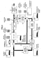
- An image encoding apparatus is constructed as.showed in FIG. 8 , for example, and an image decoding apparatus according to this invention is constructed as showed in FIG. 9 , for example.
- redundancy in the temporal direction is reduced by motion compensation inter-frame prediction.
- the DCT transformation bases are modified so that the waveform pattern of predicted image of the macro block obtained by the motion compensation prediction is captured.
- the signal is encoded and compressed by the modified transformation bases.
- the modification of the transformation bases for each pattern of the predicted image requires additional operations.
- the image encoding apparatus does not need to transmit additional information in connection with the modification of the transformation bases to the image decoding apparatus since the operation is performed using the predicted image data that are shared with the image decoding apparatus.
- the procedure of motion compensation inter-frame prediction is identical to that of the conventional method.
- FIG. 3 shows the procedure of motion compensation inter-frame prediction
- FIG. 4 shows block matching processing that is used to detect the motion vector.
- the procedure of quantizing coefficients that are obtained by transformation using the modified orthogonal bases and encoding the quantized coefficients into entropy codes is identical to that of the conventional example.
- the input image signal 101 is a signal corresponding to a framed image in a time series of framed images (The framed image to be encoded corresponds to the current frame of FIG. 3 ).
- Each macro block of the current frame is encoded by the following procedure.
- the current macro block is transferred to the motion detection unit 102 that detects motion vector 105.
- a motion compensation unit 107 using the motion vector 105, extracts a predicted image 106 of each macro block from the partially decoded image 117 stored in the frame memory 103.
- a predicted remainder signal 108 is obtained as the difference between the current macro block and the predicted image 106.
- This predicted remainder signal 108 is converted into the orthogonal transformation coefficient data 110 by the adaptive transformation unit 109.
- the transformation bases 119 used by the adaptive transformation unit 109 are generated by a transformation base operation unit 118 depending on the pattern of the predicted image 106.
- the generated transformation bases 119 are transferred to the adaptive transformation unit 109 and used for the orthogonal transformation. The operation of the transformation base operation unit 118 will be described later.
- the orthogonal transformation coefficient data 110 obtained by the adaptive transformation unit 109 are quantized by the quantization unit 111, encoded into run-length codes by scanning by the variable length encoding unit 113, and multiplexed in the compressed stream 114 for transmission.
- the motion vector 105 of each macro block is multiplexed in the compressed stream 114 for transmission.
- the quantized coefficients 112 are partially decoded by an inverse quantization unit 115 and a inverse adaptive transformation unit 116.
- the same decoded image 117 as that of the image decoding apparatus is generated by adding the partially decoded image to the predicted image 106.
- the decoded image 117 is stored in the frame memory 103 as a partially decoded image that is used for the prediction of the next frame.
- the transformation base operation unit 118 operates as follows.
- N 4
- N 4
- the transformation bases 119 for each region
- the adaptive transformation unit 109 outputs the transformation bases 119 to the adaptive transformation unit 109.
- the bases of DCT are modified so that only the transformation coefficients of the principal axis (the first row vector of the transformation matrix, and direct current components in the case of DCT) and its neighbors have a considerable amount, and each of the average brightness distribution vectors x H and x V matches the base of the principal axis.
- the base of the principal axes of the horizontal and vertical DCT transformation bases are replaced by weighted normalized average brightness distribution vectors, and correlation matrices C H and C V are obtained.
- Eigenvectors ( ⁇ H,0 - ⁇ H,N-1 and ⁇ V,0 - ⁇ V,N-1 of the correlation matrices become the new transformation bases 119.
- the transformation bases 119 form normalized orthogonal bases.
- the patterns of the average brightness distribution of the predicted image 106 in the horizontal directions and the vertical directions are reflected in the principal axis of the orthogonal transformation.
- the concentration ratio of the orthogonal transformation coefficients of the image is increased.
- the inverse adaptive transformation unit 116 inversely converts the transformation coefficients into a signal in the image space using the transpose of the transformation bases 119.
- a variable length decoding unit 120 detects a sync word indicating the top of each frame in the received compressed stream 114 and restores the motion vector 105 and the quantized orthogonal transformation coefficients 121 of each macro block.
- the motion vector 105 is transferred to the motion compensation unit 107.
- the motion compensation unit 107 in the same manner as it operates in the image encoding apparatus, obtains a partial image stored in the frame memory 122 (used in the same manner as the frame memory 103) that moves for the motion vector 105 as a predicted image 106.
- the quantized orthogonal transformation coefficients 121 are decoded by the inverse quantization unit 115 and the inverse adaptive transformation unit 116 and added to the predicted image 106 to make the final decoded image 117.
- the transformation base operation unit 118 calculates and outputs the same transformation bases 119 as the image encoding apparatus.
- the inverse adaptive transformation unit 116 using the transpose, inversely converts the transformation coefficients into the signal in the image space.
- the decoded image 117 is output to the display device at a predetermined timing to reproduce the image.
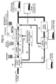
- the image encoding apparatus is constructed as showed in FIG. 11 , for example, and the image decoding apparatus according to this embodiment is constructed as showed in FIG. 12 , for example.
- This embodiment reduces the redundancy remaining in the time directions by the motion compensation inter-frame prediction, and modifies the DCT bases so that the base corresponding to the principal component can capture the waveform pattern of the predicted image of a macro block obtained by the motion compensation prediction to compress the information by encoding using the modified bases.
- Several sets of transformation bases that fit local characteristics of corresponding image are prepared, and a set of transformation bases that fits the pattern of the predicted image is selected.
- the image decoding apparatus Since the same set of transformation bases is provided to both the image encoding apparatus and the image decoding apparatus, it is not necessary to transmit information other than ID information indicating the switching of bases.
- the image decoding apparatus is required only to selects a set of bases based on the ID information and does not need to calculate bases.
- the image encoding apparatus showed in FIG. 11 employs the same procedure of the motion compensation inter-frame prediction as described in connection with the conventional example.
- the procedure is illustrated in FIG. 3
- block matching processing to detect the motion vector is illustrated in FIG. 4 .
- the procedure ( FIGS. 6A and 6B ) to quantize the coefficients obtained by the orthogonal transformation and to encode the coefficients into entropy codes are identical to the conventional example.
- the operation of the image encoding apparatus and the image decoding apparatus is described by reference to these drawings.
- an input image signal 201 is a signal of a framed image in a time series of framed images (the framed image to be encoded corresponds to the current frame of FIG. 3 ).
- the current frame is encoded in the following procedure by a macro block.
- the current macro block is transferred to the motion detection unit 202 for detecting the motion vector 205.
- the motion compensation unit 207 retrieves a predicted image 206 of each macro block by looking up partially decoded images 217 in the frame memory 203 using the motion vector 205.
- the predicted remainder signal 208 is obtained as the difference between the current macro block and the predicted image 206 and converted into the orthogonal transformation coefficient data 210 by the adaptive transformation unit 209.
- the transformation bases 219 used by the adaptive transformation unit 209 is selected by the transformation base operation unit 218 depending on the used pattern of the predicted image 206.
- the selected transformation bases 219 are transferred to the adaptive transformation unit 209 and used for the orthogonal transformation.
- the ID information 250 of a transformation base 219 for each orthogonal transformation processing is multiplexed on the compressed stream 214 and transferred to the image decoding apparatus. The operation of the transformation base operation unit 218 will be described later.
- the orthogonal transformation coefficient data 210 obtained by the adaptive transformation unit 209 are quantized by the quantization unit 211, encoded into run-length codes by the variable length encoding unit 213, and multiplexed on the compressed stream 214 for transmission.
- a motion vector 205 of each macro block is multiplexed on the compressed stream 214 and transmitted.
- the quantized coefficients 212 are partially decoded by the inverse quantization unit 215 and the inverse adaptive transformation unit 216.
- the result is added to the predicted image 206 to make the same decoded image 217 as the image decoding apparatus.
- the decoded image 217 is stored in the frame memory 203 as a partially decoded image to be used for the prediction of the next frame.
- the transformation base operation unit 218 performs the following operation.
- the adaptive transformation unit 109 As showed in FIG. 10 , average brightness distributions x H and x V in the horizontal and vertical directions are obtained for each region of the predicted image 206 to which the orthogonal transformation is applied. Waveform patterns that reflect the principal components of each region in the horizontal and vertical directions are obtained (see FIG. 10 ).
- the principal axis base is a direct current component.
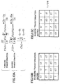
- the DCT transformation and its inverse transformation represented by the following formulae showed in FIG. 13A are performed.
- the transformation base operation unit 218 selects the transformation base A i that maximizes the inner product between the average brightness distribution vectors x H , x V and the principal axis base vector, for example.
- the concentration ratio of the orthogonal transformation coefficients of the image to be encoded is increased by selectively using a base in which the power concentration ratio of the pattern of the predicted image is high by the above procedure. Further, since the frequency in which ID information 250 is selected is biased due to the characteristics of an image, it is possible to reduce the bit amount of the ID information to be transmitted by assigning an appropriate Huffman code by the variable length encoding unit 213 and using entropy encoding such as arithmetic code.
- the image decoding apparatus showed in FIG. 12 operates as follows.
- a variable length decoding unit 220 detects a sync word indicating the top of each frame in the received compressed stream 214 and restores the transformation base ID information 250, the motion vector 205, the quantized orthogonal transformation coefficient 221 for each orthogonal transformation and for each macro block.
- the motion vector 205 is transferred to the motion compensation unit 207.
- the motion compensation unit 207 in the same manner as it operates in the image encoding apparatus, obtains a partial image stored in the frame memory 222 (used in the same manner as the frame memory 203) that moves for the motion vector 205 as a predicted image 206.
- the quantized orthogonal transformation coefficients 221 are decoded by the inverse quantization unit 215 and the inverse adaptive transformation unit 216 and added to the predicted image 206 to make the final decoded image 217.
- the transformation base storage unit 251 there are the same base set A i (see FIGS. 13 through 19 ) as the image encoding apparatus.
- a transformation base 219 is selected based on transformation base ID information 250, and the selected transformation base 219 is transferred to the inverse adaptive transformation unit 216.
- the inverse adaptive transformation unit 216 inversely transforms the transformation coefficient into a signal in an image space using the transpose of the selected transform base A i .
- the decoded image 217 is output to the display device at a predetermined timing.
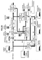
- the image encoding apparatus is constructed as showed in FIG. 20 , for example, and the image decoding apparatus is constructed as showed in FIG. 21 , for example.
- the transformation base operation unit 218A transmits flag information 250A indicating which the DCT base or the base determined by the transformation base operation unit 218A to the image decoding apparatus by multiplexing the flag information 250A to the compressed stream.
- the transformation base 219 thus obtained is transmitted to the adaptive transformation unit 209A and used for transformation.
- the above flag information 250A is extracted from the compressed stream and input to the transformation base operation unit 218B. If the transformation base operation unit 218B determines that a base other than DCT is used, the transformation base operation unit 218B identifies a transformation base A i using the completely same standard as used by the image encoding apparatus and outputs it as the transformation base 219. If the transformation base operation unit 218B determines that the DCT base is used, the transformation base operation unit 218B outputs the DCT base as the transformation base 219.
- the image decoding apparatus can use the completely same predicted image 206 as used by the image encoding apparatus. It is possible to use the same standard of judgment as described in connection with the above image encoding apparatus. That is, one can obtain the average brightness distribution vectors x H and x V in the horizontal and vertical directions of each region of the predicted image 206 to which the orthogonal transformation is applied and select a transformation base A i that maximizes the inner product between the average brightness distribution vectors and the principal axis base vector.
- the transformation base 219 thus obtained is used by the inverse adaptive transformation unit 216 to reproduce the signal in the image space by inversely transforming the transformation coefficient.
- the receiving side automatically determine which the DCT base being the reference of transformation bases or the transformation base A i based on the activity (for example, the divergence of brightness and the absolute difference between the maximum and minimum of brightness) of a region of the reference image instead of transmitting the flag information indicating which the DCT base or the transformation base A i . If the activity is high, the transformation base ID information is transmitted by the encoding side, and if the activity is low, the receiving side uses the DCT base instead of transmitting the transformation base ID information. If the activity of the reference image region is higher than a predetermined value, the receiving side determines that a transformation bases is designated, and decodes the received transformation base ID information.
- the activity for example, the divergence of brightness and the absolute difference between the maximum and minimum of brightness
- the image encoding apparatus according to this embodiment is constructed as showed in FIG. 22 , for example, and the image decoding apparatus according to this embodiment is constructed as showed in FIG. 23 , for example.
- the image encoding apparatus transmits the transformation base obtained thereby as encoded data to the image decoding apparatus so that the image decoding apparatus does not need to calculate the base.
- an input image signal 301 is a signal of frame image in a time series of frame images (The frame image to be encoded corresponds to the current frame of FIG. 3 ).
- the current frame is encoded by a macro block in the following procedure.
- the current macro block is transferred to the motion detection unit 302, and the motion detection unit 302 detects the motion vector 305.
- the motion compensation unit 307 retrieves a predicted image 306 of each macro block by reference to the partially decoded image 317 stored in the frame memory 303 using the motion vector 305.
- the predicted remainder signal 308 is obtained as the difference between the current macro block and the predicted image 306, and transformed into the orthogonal transformation coefficient data 310 by the adaptive transformation unit 309.
- the transformation base 319 that the adaptive transformation unit 309 uses is generated by the transformation base operation unit 318 depending on the pattern of the used predicted image 306. Since the same transformation base is used at the decoding side, each transformation base vector of the transformation base 319 is encoded and multiplexed on the compressed stream 314. The transformation base 319 is also transferred to the adaptive transformation unit 309 and used for the orthogonal transformation.
- the operation of the transformation base operation unit 318 is exactly identical to that of the transformation base operation unit 118 according to the first embodiment described above.
- the orthogonal transformation coefficient data 310 obtained by the adaptive transformation unit 309 are quantized by the quantization unit 311, scanned and encoded into run-length codes by the variable length encoding unit 313, and multiplexed on the compressed stream 314 for transmission.
- the motion vector 305 is multiplexed on the compressed stream 314 by a macro block and transmitted.
- the quantized coefficient 312 is partially decoded by the inverse quantization unit 315 and the inverse adaptive transformation unit 316.
- the result is added to the predicted image 306 to generate the same decoded image 317 as the image decoding apparatus. Because the decoded image 317 is used for the prediction of the next frame, the decoded image 317 is stored in the frame memory 303 as a partially decoded image.
- the variable length decoding unit 320 detects a sync word indicating the top of each frame and reproduces the transformation base 319 used for each orthogonal transformation, the motion vector 305, the quantized orthogonal transformation coefficient 321.
- the motion vector 305 is transferred to the motion compensation unit 307.
- the motion compensation unit 307 in the same manner in which the motion compensation unit of the image encoding apparatus operates, retrieves a portion of image that has moved for the motion vector 305 as the predicted image 306 from the frame memory 322 (used in the same manner in which the frame memory 303 is used).
- the quantized orthogonal transformation coefficient 321 is decoded through the inverse quantization unit 315 and the inverse adaptive transformation unit 316, and becomes the final decoded image 317 by being added to the predicted image 306.
- the inverse adaptive transformation unit 316 inversely transforms the transformation coefficient using the transpose of the transformation base 319 to reproduce a signal in an image space.
- the decoded image 317 is output to the display device at a predetermined timing to reproduce the image.
- the image encoding apparatus according to this embodiment is constructed as showed in FIG. 24 , for example, and the image decoding apparatus according to this embodiment is constructed as showed in FIG. 25 , for example.
- the input image signal 401 represents a signal of each frame image in a time series of frame images (the frame image to be encoded corresponds to the current frame of FIG. 3 ).
- the current frame is encoded by a macro block in the following procedure.
- the current macro block is transferred to the motion detection unit 402, and the motion detection unit 402 detects the motion vector 405.
- the motion compensation unit 407 retrieves the predicted image 406 of each macro block from the.frame memory 403 by reference to partially decoded image 417 using the motion vector 405.
- the predicted remainder signal 408 is obtained as the difference between the current macro block and the predicted image 406, and converted into the orthogonal transformation coefficient data 410 by the adaptive transformation unit 409.
- the transformation base 419 that is used by the adaptive transformation unit 409 is adaptively selected by the transformation base operation unit 418 depending on the pattern of the predicted image 406.
- the selected transformation base 419 is transferred to the adaptive transformation unit 409 and used for the orthogonal transformation.
- the ID information 450 of the transformation base 419 by an orthogonal transformation operation is multiplexed on the compressed stream 414 and transmitted to the image decoding apparatus.
- the transformation base operation unit 418 when the transformation base operation unit 418 generates another transformation base that is no included in the base set A i at the point of time, the transformation base is multiplexed on the compressed stream 414 through the variable length encoding unit 413 and transmitted with the ID information 450.
- the ID information 450 that is transmitted means the ID information of a base that is replaced by the transformation base that is transmitted at the same time. The operation of the transformation base operation unit 418 will be described later.
- the orthogonal transformation coefficient data 410 obtained by the adaptive transformation unit 409 is quantized by the quantization unit 411, scanned and encoded into run-length codes by the variable length encoding unit 413, and multiplexed on the compressed stream for transmission.
- the motion vector 405 is also multiplexed on the compressed stream 414 by a macro block and transmitted.
- the quantized coefficient 412 is partially decoded by the inverse quantization unit 415 and the inverse adaptive transformation unit 416.
- the same decoded image 417 as that of the image decoding apparatus is generated by adding the partially decoded image and the predicted image 406. Since the decoded image 417 is used for the prediction of the next frame, the decoded image 417 is stored in the frame memory 403 as the partially decoded image.
- the transformation base operation unit 418 operates as follows.
- the transformation base operation unit 418 first obtains average brightness distribution x H and x V in the horizontal and vertical directions for each region of the predicted image 406 to which the orthogonal transformation is applied.
- a waveform pattern that reflects the principal components of the horizontal and vertical directions of each region is obtained (see FIG. 10 ).
- the transformation base operation unit 418 calculates a base (named A') using x H and x V .
- A' a base of which inner product (similarity information) is the smallest is replaced with A'.
- A' is selected, the amount of transmitted codes increases since the base A' needs to be transmitted.
- the image decoding apparatus showed in FIG. 25 operates as follows.
- the variable length decoding unit 420 in response to reception of the compressed stream 414, the variable length decoding unit 420 detects a sync word indicating the top of each frame and then, decodes the transformation base ID information 450 used for each orthogonal transformation, the transformation base 419 required in the case where a base is replaced, the motion vector 405, and the quantized orthogonal transformation coefficient 421.
- the motion vector 405 is transferred to the motion compensation unit 407, and the motion compensation unit 407 retrieves a portion of image that is moved for the motion vector 405 from the frame memory 422. (used in the same manner in which the frame memory 403 is used) as the predicted image 406.
- the quantized orthogonal transformation coefficient 421 is decoded by the inverse quantization unit 415 and the inverse adaptive transformation unit 416, and then, added to the predicted image 406 to make the final decoded image 417.
- a base 419 corresponding to the transformation base ID information 450 is selected from the same base set A i stored in the transformation base storage unit 418, and transferred to the inverse adaptive transformation unit 416.
- a base in the base sets A i corresponding to the ID information 450 is replaced with the transformation base 419, and the transformation base 419 is transferred, as is, to the inverse adaptive transformation unit 416.
- the inverse adaptive transformation unit 416 inversely transforms the transformation coefficient using the transpose of the selected base and reproduces a signal in the image space.
- the decoded image 417 is output to the display device at a predetermined timing to reproduce the image.
- the image encoding apparatus is constructed as showed in FIG. 26 , for example, and the image decoding apparatus according to this embodiment is constructed as showed in FIG. 27 , for example.
- an optimum transformation base for the predicted image is obtained using a high correlation between the predicted image obtained by the motion compensation inter-frame prediction and the image to be encoded (the current macro block), and the optimum transformation base is directly applied to the image to be encoded. That is, an intra-frame signal, instead of the predicted remainder signal, is directly encoded by the orthogonal transformation. Accordingly, since the transformation coefficients of the current macro block signal are concentrated near the principal axis, even the intra-frame signal can encode the image to be encoded with a high efficiency. Additionally, the predicted image is common to both the image encoding apparatus and the image decoding apparatus, and both apparatuses can generate the orthogonal transformation base following the same procedure. It is not necessary to transmit the base data.
- the input image signal 501 indicates the signal of a frame image in a time series of frame images (the frame image that is an object of encoding corresponds to the current frame of FIG. 3 ).
- the current frame is encoded by a macro block by the following procedure.
- the current macro block is transferred to the motion detection unit 502 that detects the motion vector 505.
- the motion compensation unit 507 retrieves the predicted image 506 of each macro block from the partially decoded image 517 stored in the frame memory 503.
- the predicted image 506 is transmitted, without being subtracted from the current macro block, to the transformation base operation unit 518 and used for the generation of the transformation base 519 that is used to encode the current macro block.
- the transformation base operation unit 518 generates a KL (Karhunen-Loeve) transformation base using the predicted image 506 as a source.
- KL transformation generates the optimum, from the standpoint of power concentration, normalized orthogonal transformation from a signal that complies with stationary probability process. Accordingly, in the case of an image signal that is not stationary, it is necessary to obtain the KL transformation base for each transformation and transmit the KL transformation base to the image decoding apparatus so that the image decoding apparatus can use the same base. Since the KL transformation is obtained based on the predicted image, it is not necessary to transmit the KL transformation base to the image decoding apparatus.
- the predicted image 506 is extracted as a pattern that is similar to the current macro block based on the motion compensation inter-frame prediction algorithm. That is, it is probable that the signal distribution of the predicted image 506 is substantially similar to that of the current macro block. From this standpoint, if the KL transformation based on the predicted image is used instead of DCT, the power concentration of the transformation coefficient of the current macro block can be increased. In other words, the signal can be represented by fewer transformation coefficients.
- the current macro block is converted into orthogonal transformation coefficient data 510 by the adaptive transformation unit 509 using the KL transformation base of the predicted image 506.
- the orthogonal transformation coefficient data 510 is quantized by the quantization unit 511, scanned and encoded into a run-length code by the variable length encoding unit 513, and multiplexed on the compressed stream for transmission.
- the motion vector 505 is also multiplexed on the compressed stream 514 by a macro block and transmitted.
- the quantized coefficient 512 is partially decoded through the inverse quantization unit 515 and the inverse adaptive transformation unit 516, and the reproduced image 517 that is identical to the reproduced image of the image decoding apparatus is generated.
- the reproduced image 517 is stored in the frame memory 503 and used for the prediction of the next frame.
- the image decoding apparatus showed in FIG. 27 operates in the following manner.
- variable length decoding unit 520 in response to reception of the compressed stream 514, the variable length decoding unit 520 detects a sync word indicating the top of each frame, and then, reproduces the motion vector 505 and the quantized orthogonal transformation coefficient 521 of each macro block.
- the motion vector 505 is transferred to the motion compensation unit 507.
- the motion compensation unit 507 in the same manner in which that of the image encoding apparatus, retrieves a portion of image that has moved for the motion vector 505 from the frame memory 522 (used in the same manner as the frame memory 503 is used) as the predicted image 506.
- the quantized orthogonal transformation coefficient 521 is decoded through the inverse quantization unit 515 and the inverse adaptive transformation unit 516, and makes the decoded image 517.
- the transformation base operation unit 518 in the same manner of the image encoding apparatus, obtains the KL transformation base using the predicted image 506 as a source and outputs it as the transformation base 519.
- the inverse adaptive transformation unit 516 performs an inverse transformation on the transformation coefficient based on the transformation base 519 and reproduces a signal in the image space.
- the decoded image 517 is output to the display device at a predetermined timing and displayed on it.
- the image encoding apparatus is constructed as showed in FIG. 28 , for example, and the image decoding apparatus according to this embodiment is constructed as showed in FIG. 29 , for example.
- This embodiment relates to an apparatus that encodes and decodes an image by encoding method to which a technique called "Matching Pursuits" is applied and introduces an adaptive base reflecting the signal pattern of the predicted image as described in connection with the previous embodiments.
- a technique called "Matching Pursuits” an image signal f that is the object of encoding can be represented as the following formula 2 using an over-complete base set g k provided in advance.
- n is the number of base search steps
- R n f is a signal for which a base is searched in the n th search step (hereinafter, called the n th partial signal waveform); and
- g kn is a base that maximizes an inner product with R n f.
- R m f is a remaining component for which a base is searched in the m th search step. That is, the more the number of steps is, the more accurate the signal f is represented.
- the signal that is the object of the n+1 th search step is as follows.
- R n ⁇ f - ⁇ R n ⁇ f , g k n ⁇ g k n This means that the more the number of bases is, the more accurately the signal f can be represented.
- R n F is a signal waveform defined in a predetermined window range centered at an arbitral position in the image.
- an input image signal is a signal of a frame image in a time series of image frames (the frame image that is the object of encoding corresponds to the current frame of FIG. 3 ).
- the current frame is encoded in the following procedure.
- the current frame is transferred to the motion detection unit 602, and the motion vector 605 is detected by a macro block.
- the motion compensation unit 607 retrieves the predicted image 606 of the current frame from the partially decoded image 604 stored in the frame memory 603 using the motion vector 605.
- the predicted remainder signal 608 is obtained as the difference between the predicted image 606 and the current frame (the input image signal 601).
- the base search unit 609 generates a base parameter (hereinafter referred to as "atom") 610 for the predicted remainder signal 608 based on the above "Matching Pursuits" algorithm.
- the base set g k is stored in a base codebook 619. If one can find a base that can accurately represent the partial signal waveform in the initial search step, the one can represent the partial signal waveform with a few atoms, that is, a small amount of codes, to such an extent that the base accurately represent the partial signal waveform.
- any vector of which waveform pattern satisfies linearly independent from the vectors included in g k and of which a norm is one (1) can be used as a new base.
- this embodiment is constructed so that a waveform pattern of image signals included in the predicted image 606 can be used as a new base.
- the pattern of the predicted image signal sometimes substantially correlates to that of the predicted remainder signal; in the case where the motion compensation prediction fails in the outline region of an object, an edge pattern similar to the predicted image appears in the predicted remainder signal, for example.
- the predicted remainder signal can be efficiently represented.
- the base operation unit 618 generates a candidate of a new base h j 652.
- h j P j / P j
- P j P j / P j
- P j P j / P j
- P j P j / P j
- P j P j / P j
- P j P j / P j
- P j P j / P j
- P j is a waveform vector generated from the partially predicted image
- " is a norm of P j .
- the partially predicted image means a partial signal waveform that is located at the same position as the partial signal waveform of the object of base search. Since the partial predicted image is located at the same position in the screen as the position information of an atom that is to be encoded, the image decoding apparatus does not need additional information to identify the position of the partial predicted image.
- P j The following may be used as P j :
- a new base set h j is generated by the formula 5 using P j based on the partial predicted image. Since h j is generated using only signals included in the predicted image 606, it is not necessary to transmit base vectors. One needs to transmit only the index of h j instead of g k . It is possible to increase the candidates for a new base without transmitting additional amount of codes.
- Flag information 650 for identifying whether to use g k or h j may be encoded.
- the base search unit 609 outputs an atom parameter 610 including an index of g k or h j , an inner product of the partial signal waveform and the base, and position of the partial signal waveform, in addition to the flag information 650, to the base encoding unit 611.
- the base encoding unit 611 quantizes the atom parameter 610, transfers the encoded data to the variable length encoding unit 613, and additionally, inputs the encoded data to the base decoding unit 616.
- the base decoding unit 616 reproduces the image signal using a base pattern encoded from g k or h j that are switched by flag information 650 and the switch 651. Subsequently, the reproduced image signal is added to the predicted image 606 to generate the partially decoded image 617, which is stored in the frame memory 603 and used for the compensation prediction of the next frame.
- the image decoding apparatus showed in FIG. 29 operates in the following manner.
- variable length decoding unit 620 in response to reception of the compressed stream 614, the variable length decoding unit 620 detects a sync word indicating the top of each frame, and reproduces the motion vector 605 and the atom parameter 621 by a macro block.
- the motion vector 605 is transferred to the motion compensation unit 607, and the motion compensation unit 607 retrieves an image portion that moved for the motion vector 605 from the frame memory 622 (used as the frame memory 603) as the predicted image 606.
- the atom parameter 621 is decoded by the base decoding unit 616.
- a base to be used for decoding is determined based on the flag information 650 by switching the base codebook g k 619 originally provided and the base h j generated from the predicted image 606.
- the base operation unit 618 When h j is used, the base operation unit 618 generates h j from the predicted image 606 complying with the same rule as the encoding side.
- the output of the base decoding unit 616 is added to the predicted image 606 to make the decoded image 617.
- the decoded image 617 is stored in the frame memory 622 and used for the compensation of upcoming frames.
- the decoding image 617 is output to the display device at a predetermined timing to reproduce the image.
- a signal that is an object to be encoded can be transformed and encoded using a transformation base matching to a characteristic of the signal, and the encoded signal can be transformed using the same transformation base after decoding the encoded signal.
- the encoding and decoding of a signal becomes more efficient.
Landscapes
- Engineering & Computer Science (AREA)
- Multimedia (AREA)
- Signal Processing (AREA)
- Physics & Mathematics (AREA)
- Discrete Mathematics (AREA)
- General Physics & Mathematics (AREA)
- Computing Systems (AREA)
- Theoretical Computer Science (AREA)
- Compression Or Coding Systems Of Tv Signals (AREA)
- Compression, Expansion, Code Conversion, And Decoders (AREA)
- Analogue/Digital Conversion (AREA)
Claims (99)
- Verfahren zum Transformieren einer Restsignals bezogen auf ein Bildsignal (101) in Übereinstimmung mit einer Transformation, um ein codiertes Bildsignal zu produzieren, wobei das Verfahren umfasst:Vorausberechnen eines bewegungskompensierten Signals (106) des Bildsignals; gekennzeichnet durchAbleiten einer Transformationsbasis (119) zur Verwendung für die Transformation basierend auf Leuchtdichteninformation des vorausberechneten bewegungskompensierten Signals durch Ersetzen von Basen von Hauptachsen von horizontalen und vertikalen DCT-Transformationsbasen einer DCC-Transformation durch gewichtete, normalisierte, gemittelte Helligkeitsverteilungsvektoren (XH, XV), Anzeigen einer mittlere Helligkeit in horizontalen und vertikalen Richtungen jeder jeweiliger Zeilen und Spalten von Bildpunktblöcken des vorausberechneten bewegungskompensierten Signals, auf das die Transformation angewendet wird, und Erhalten von Korrelationsmatrizen (CH, CV), wobei Eigenvektoren (ϕ H,0 - ϕ H,N-1; ϕ V,0 - ϕ V,N-1) der Korrelationsmatrizen die neuen Transformationsbasen werden und die Transformationsbasen normalisierte orthogonale Basen bilden; undTransformieren eines Restsignals, wobei das Restsignal das Bildsignal ist, von dem das vorausberechnete bewegungskompensierte Signal subtrahiert wird, in Übereinstimmung mit der Transformation unter Verwendung der abgeleiteten Transformationsbasis.
- Verfahren nach Anspruch 1, wobei die DCT-Transformationsbasis ersetzt wird durch Auswählen eines von einer Vielzahl von Vorlagen von Wellenformmustern, das ein inneres Produkt mit den gemittelten Helligkeitsverteilungsvektoren maximiert.
- Verfahren nach Anspruch 1, wobei das vorausberechnete bewegungskompensierte Signal identisch mit einem Signal ist, das erhalten werden soll, wenn das codierte Bildsignal, das durch das Verfahren codiert wird, decodiert wird.
- Verfahren nach Anspruch 3, wobei das Restsignal durch ein Bewegungskompensations-Vorausberechnungsverfahren aus einem Eingangs-Original-Bildsignal erhalten wird.
- Verfahren nach Anspruch 1, wobei die Transformationsbasis basierend auf einer Charakteristik des vorausberechneten bewegungskompensierten Signals erzeugt wird.
- Verfahren nach Anspruch 5, wobei, beim Ableiten der Transformationsbasis, eine neue Transformationsbasis durch Ersetzen einer Transformationsbasis erzeugt wird, die als eine Referenz vorbestimmt ist basierend auf einer Charakteristik einer Signalwertverteilung des voraus berechneten bewegungskompensierten Signals.
- Verfahren nach Anspruch 1, wobei, beim Ableiten der Transformationsbasis,
eine Vielzahl von Wellenformmustern erzeugt werden, die als eine Charakteristik einer Helligkeitsverteilung eines Referenzsignals auftreten können;
eine der Vielzahl von Wellenformmustern in Übereinstimmung mit einer Ähnlichkeit mit einer Charakteristik einer Helligkeitsverteilung des Referenzsignals ausgewählt wird; und
eine neue Transformationsbasis erzeugt wird durch Ersetzen einer DCT-Transformation basierend auf einem Zusammenhang zwischen dem ausgewählten Wellenformmuster und einer DCT-Transformationsbasis. - Verfahren nach Anspruch 1, wobei, beim Ableiten der Transformationsbasis, eine Transformationsbasis, die beim Transformieren des Restsignals verwendet werden soll, aus einer Vielzahl von vorbestimmten Transformationsbasen ausgewählt wird basierend auf einer Charakteristik des vorausberechneten bewegungskompensierten Signals.
- Verfahren nach Anspruch 8, wobei, beim Ableiten der Transformationsbasis,
ein Zusammenhang zwischen jeder der Vielzahl von vorbestimmten Transformationsbasen und einer Charakteristik einer Signalwertverteilung des vorausberechneten bewegungskompensierten Signals erhalten wird; und
eine Transformationsbasis ausgewählt wird, deren Charakteristik einer Signalwertverteilung einem vorbestimmten Standard genügt. - Verfahren nach Anspruch 1, wobei, beim Ableiten der Transformationsbasis,
eine Ähnlichkeit zwischen einem Basisvektor, der eine Charakteristik jeder der Vielzahl von vorbestimmten Transformationsbasen anzeigt, und einer Charakteristik einer Helligkeitsverteilung eines Referenzsignals, das zu dem Bildsignal korreliert; und
eine Transformationsbasis, die den Basisvektor aufweist, von dem eine Ähnlichkeit mit der Charakteristik einer Helligkeitsverteilung des Referenzsignals einem vorbestimmten Standard genügt, aus der Vielzahl von Transformationsbasen ausgewählt wird. - Verfahren nach Anspruch 10, wobei die Vielzahl von Transformationsbasen eine DCT-Basis beinhaltet; und
beim Ableiten der Transformationsbasis, entweder eine Transformationsbasis, die aus der Vielzahl von Transformationsbasen verschieden von einer DCT-Basis basierend auf der Ähnlichkeit ausgewählt wird, oder eine DCT-Basis ausgewählt wird, welche auch immer eine bessere Codiereffizienz zeigt. - Verfahren nach Anspruch 8, wobei Information zum Identifizieren der Transformationsbasis, die beim Ableiten der Transformationsbasis ausgewählt wird, mit dem Restsignal codiert wird.
- Verfahren nach Anspruch 11, wobei Flag-Information, die anzeigt, ob eine DCT-Basis ausgewählt wird, mit dem Restsignal codiert wird.
- Verfahren nach Anspruch 1, wobei die Transformationsbasis, die beim Ableiten der Transformationsbasis abgeleitet wird, mit dem Restsignal codiert wird.
- Verfahren nach Anspruch 1, wobei, beim Ableiten der Transformationsbasis, die Transformationsbasis basierend auf dem vorausberechneten bewegungskompensierten Signal erzeugt wird; und
eine Transformationsbasis, die beim Transformieren des Restsignals zu verwenden ist, aus einer Vielzahl von Transformationsbasen und der erzeugten Transformationsbasis basierend auf der Charakteristik des vorausberechneten bewegungskompensierten Signals ausgewählt wird. - Verfahren nach Anspruch 15, wobei, in dem Fall, dass die erzeugte Transformationsbasis als die Transformationsbasis ausgewählt wird, die bei einer Transformation des Restsignals zu verwenden ist, die erzeugte Transformationsbasis zu der Vielzahl von Transformationsbasen hinzugefügt wird.
- Verfahren nach Anspruch 16, wobei eine Transformationsbasis, die basierend auf der Charakteristik des vorausberechneten bewegungskompensierten Signals und einem gegenseitigen Zusammenhang mit einer anderen der Vielzahl von Transformationsbasen bestimmt wird, aus der Vielzahl von Transformationsbasen gelöscht wird.
- Verfahren nach Anspruch 1, wobei, beim Ableiten der Transformationsbasis, eine neue Transformationsbasis erzeugt wird durch Ersetzen einer DCT-Transformationsbasis basierend auf einer Charakteristik einer Helligkeitsverteilung des vorausberechneten bewegungskompensierten Signals korreliert mit dem Bildsignal;
eine Ähnlichkeit zwischen einem Basisvektor und der Charakteristik der Helligkeitsverteilung des vorausberechneten bewegungskompensierten Signals erhalten wird, wobei der Basisvektor ein Merkmal jeder der Vielzahl von vorbestimmten Transformationsbasen und der erzeugten Transformationsbasis anzeigt; und
eine Transformationsbasis mit dem Basisvektor, dessen Ähnlichkeit mit der Charakteristik einer Helligkeitsverteilung des vorausberechneten bewegungskompensierten Signals einem erste Standard genügt, aus der Vielzahl von Transformationsbasen und der erzeugten Transformationsbasis ausgewählt wird, zur Verwendung bei einer Transformation des Restsignals. - Verfahren nach Anspruch 18, wobei, in dem Fall, dass die erzeugte Transformationsbasis als eine Transformationsbasis ausgewählt wird, die bei einer Transformation des Restsignals zu verwenden ist, der erzeugte Transformationsschritt zu der Vielzahl von Transformationsbasen hinzugefügt wird; und
eine Transformationsbasis mit dem Basisvektor, dessen Ähnlichkeit mit der Charakteristik einer Helligkeitsverteilung des vorausberechneten bewegungskompensierten Signals einem zweiten Standard genügt, aus der Vielzahl von Transformationsbasen gelöscht wird. - Verfahren nach Anspruch 19, wobei eine der Vielzahl von Transformationsbasen basierend auf der Charakteristik des vorausberechneten bewegungskompensierten Signals ausgewählt wird; und
das Objektsignal unter Verwendung der ausgewählten der Vielzahl von Transformationsbasen und der erzeugten Transformationsbasis codiert wird, und entweder die ausgewählte der Vielzahl von Transformationsbasen oder die erzeugte Transformationsbasis basierend auf Codierergebnissen ausgewählt wird. - Verfahren nach Anspruch 15, wobei, wenn eine Transformationsbasis, die bei einer Transformation des Bildsignals zu verwenden ist, aus der Vielzahl von Transformationsbasen und der erzeugten Transformationsbasis ausgewählt wird, eine der Vielzahl von Transformationsbasen priorisiert wird.
- Verfahren nach Anspruch 15, wobei, in dem Fall, dass die erzeugt Transformationsbasis ausgewählt wird, die erzeugte Transformationsbasis mit dem Restsignal codiert wird.
- Verfahren nach Anspruch 16, wobei die erzeugte Transformationsbasis Information zum Identifizieren der gelöschten der Vielzahl von Transformationsbasen mit dem Restsignal codiert wird.
- Verfahren nach Anspruch 1, wobei das vorausberechnete bewegungskompensierte Signal aus vorausberechnetes Bildsignal ist, das aus einem Eingangsoriginalbildsignal durch Bewegungskompensations-Vorausberechnung erhalten wird; und
das Eingangsoriginalbildsignal das Bildsignal darstellt. - Verfahren nach Anspruch 24, wobei, beim Ableiten der Transformationsbasis, eine Karhunen-Loeve-Transformationsbasis, die aus einem vorausberechneten Bild erhalten wird, das ein Referenzsignal als eine Quelle ist, als eine Transformationsbasis erzeugt wird, die bei einer Transformation des Restsignals zu verwenden ist.
- Verfahren nach Anspruch 1, wobei eine Teilsignalwellenform des Bildsignals identifiziert wird und die Teilsignalwellenform in Ähnlichkeitsinformation umgewandelt wird, die eine Ähnlichkeit zwischen der Teilsignalwellenform und einem Wellenformvektor anzeigt, der einen Transformationsvektor darstellt;
Information zum Identifizieren des Wellenformvektors, die Ähnlichkeitsinformation und eine Position der Teilsignalwellenform in dem Bildsignal codiert werden; und
beim Ableiten der Transformationsbasis, ein Wellenformvektor, der eine Transformationsbasis darstellt, erzeugt wird basierend auf einer Charakteristik eines Teilsignals des vorausberechneten bewegungskompensierten Signals entsprechen der Teilsignalwellenform des Bildsignals. - Verfahren nach Anspruch 26, wobei ein Wellenformvektor, der als eine Transformationsbasis zu verwenden ist, ausgewählt wird basierend auf einem Ähnlichkeitszusammenhang zwischen jedem Wellenformvektor, der in einer vorbestimmten Gruppe von Wellenformvektoren beinhaltet ist, und dem erzeugten Wellenformvektor und der Teilsignalwellenform.
- Verfahren nach Anspruch 26, wobei die Helligkeitsinformation auf einem inneren Produkt zwischen der Teilsignalwellenform und einem Wellenformvektor basiert.
- Verfahren nach Anspruch 26, wobei Information, die den zu codierenden Wellenformvektor anzeigt, Flag-Information beinhaltet, die anzeigt, ob der Wellenformvektor, der in der Gruppe von Wellenformvektoren enthalten ist, oder der erzeugten Wellenformvektor ausgewählt wird.
- Vorrichtung zum Transformieren eines Restsignals bezogen auf ein Bildsignal (101) in Übereinstimmung mit einer Transformation, um ein codiertes Bildsignal zu produzieren, wobei die Vorrichtung umfasst:eine erste Einheit (107), eingerichtet zum Vorausberechnen eines bewegungskompensierten Signals (106) des Bildsignals; gekennzeichnet durcheine zweite Einheit (118), eingerichtet zum Ableiten einer Transformationsbasis (119), die für die Transformation zu verwenden ist, basierend auf Leuchtdichteninformation des vorausberechneten bewegungskompensierten Signals durch Ersetzen von Basen von Hauptachsen von horizontalen und vertikalen DCT-Transformationsbasen einer DCT-Transformation durch gewichtete, normalisierte, gemittelte Helligkeitsverteilungsvektoren (XH, XV), Anzeigen einer gemittelten Helligkeit in horizontalen und vertikalen Richtungen jeder jeweiligen Zeile und Spalte eines Bildpunktblocks des vorausberechneten bewegungskompensierten Signals, auf das die Transformation angewendet wird, und Erhalten von Korrelationsmatrizen (CH, CV), wobei Eigenvektoren (ϕ H,0 - ϕ H,N-1; ϕ V,0 - ϕ V,N-1) der Korrelationsmatrizen die neuen Transformationsbasen werden und die Transformationsbasen normalisierte orthogonale Basen bilden; undeine dritte Einheit eingerichtet zum Transformieren eines Restsignals, wobei das Restsignal das Bildsignal ist, von dem das vorausberechnete bewegungskompensierte Signal subtrahiert wird in Übereinstimmung mit der Transformation unter Verwendung der abgeleiteten Basis.
- Vorrichtung nach Anspruch 30, wobei die zweite Einheit eingerichtet ist zum Ersetzen der DCT-Transformationsbasis durch Auswählen einer von einer Vielzahl von Vorlagen von Wellenformmustern, die ein inneres Produkt mit den gemittelten Helligkeitsverteilungsvektoren maximiert.
- Vorrichtung nach Anspruch 30, wobei das vorausberechnete bewegungskompensierte Signal identisch mit einem Signal ist, erhalten werden soll, wenn das codierte Bildsignal, das durch die Vorrichtung codiert wird, decodiert wird.
- Vorrichtung nach Anspruch 30, wobei das Restsignal erhalten wird durch ein Bewegungskompensations-Vorausberechnungsverfahren aus einem Eingangsoriginalbildsignal.
- Vorrichtung nach Anspruch 30, wobei die zweite Einheit die Transformationsbasis basierend auf einer Charakteristik des vorausberechneten bewegungskompensierten Signals erzeugt.
- Vorrichtung nach Anspruch 34, wobei die Transformationsbasis-Erzeugungseinheit eine neue Transformationsbasis erzeugt durch Ersetzen einer Transformationsbasis, die als eine Referenz vorbestimmt wird, basierend auf einer Charakteristik einer Signalwertverteilung des vorausberechneten bewegungskompensierten Signals.
- Vorrichtung nach Anspruch 30, wobei die zweite Einheit eine Transformationsbasis, die von der dritten Einheit verwendet werden soll, einer Vielzahl von vorbestimmten Transformationsbasen auswählt aus basierend auf einer Charakteristik des vorausberechneten bewegungskompensierten Signals.
- Vorrichtung nach Anspruch 36, wobei die Basisauswahleinheit einen Zusammenhang zwischen jeder der Vielzahl von vorbestimmten Transformationsbasen und einer Charakteristik einer Signalwertverteilung des vorausberechneten bewegungskompensierten Signals erhält und eine Transformationsbasis auswählt, deren Charakteristik einer Signalwertverteilung einem vorbestimmten Standard genügt.
- Vorrichtung nach Anspruch 30, wobei die zweite Einheit einen Ähnlichkeitszusammenhang zwischen einem Basisvektor, der eine Charakteristik jeder einer Vielzahl von vorbestimmten Transformationsbasen anzeigt, und einer Charakteristik einer Helligkeitsverteilung eines Referenzsignals korrelierend mit dem Bildsignal erhält; und
die zweite Einheit eine Transformationsbasis, die den Basisvektor aufweist, dessen Ähnlichkeit mit der Charakteristik einer Helligkeitsverteilung des Referenzsignals einem vorbestimmten Standard genügt, aus der Vielzahl von Transformationsbasen auswählt. - Vorrichtung nach Anspruch 38, wobei die Vielzahl von Transformationsbasen eine DCT-Basis beinhaltet; und
die Basisauswahleinheit entweder eine Transformationsbasis ausgewählt, die aus der Vielzahl von Transformationsbasen verschieden von einer Transformationsbasis basierend auf der Ähnlichkeit der DCT-Basis auswählt wird, welche auch immer eine bessere Codiereffizienz zeigt. - Vorrichtung nach Anspruch 36, wobei Information zum Identifizieren der von der zweiten Einheit ausgewählten Transformationsbasis mit dem Restsignal codiert wird.
- Vorrichtung nach Anspruch 39, wobei Flag-Information, die anzeigt, ob eine DCT-Basis ausgewählt wird, mit dem Restsignal codiert wird.
- Vorrichtung nach Anspruch 30, wobei die von der zweiten Einheit abgeleitete Transformationsbasis mit dem Restsignal codiert wird.
- Vorrichtung nach Anspruch 30, wobei die zweite Einheit weiterhin umfasst:eine Basiserzeugungseinheit, die die Transformationsbasis basierend auf einer Charakteristik des vorausberechneten bewegungskompensierten Signals erzeugt; undeine Basisauswahleinheit, die eine Transformationsbasis, die von der dritten Einheit zu verwenden ist, aus der Vielzahl von Transformationsbasen und der erzeugten Transformationsbasis auswählt basierend auf der Charakteristik des vorausberechneten bewegungskompensierten Signals.
- Vorrichtung nach Anspruch 43, wobei, in dem Fall, dass die erzeugte Transformationsbasis als die Transformationsbasis, die von der dritten Einheit zu verwenden ist, ausgewählt wird, die erzeugte Transformationsbasis zu der Vielzahl von Transformationsbasen hinzugefügt wird.
- Vorrichtung nach Anspruch 44, wobei eine Transformationsbasis, die basierend auf der Charakteristik des vorausberechneten bewegungskompensierten Signals und einem gegenseitigen Zusammenhang der Vielzahl von Transformationsbasen bestimmt wird, aus der Vielzahl von Transformationsbasen gelöscht wird.
- Vorrichtung nach Anspruch 30, wobei die zweite Einheit weiterhin umfasst:eine Basiserzeugungseinheit, die eine neue Transformationsbasis erzeugt durch Ersetzen einer DCT-Transformationsbasis basierend auf einer Charakteristik einer Helligkeitsverteilung des vorausberechneten bewegungskompensierten Signals korreliert mit dem Bildsignal;eine Basisauswahleinheit, die einen Ähnlichkeitszusammenhang zwischen einem Basisvektor und der Charakteristik einer Helligkeitsverteilung des vorausberechneten bewegungskompensierten Signals erhält, wobei der Basisvektor ein Merkmal jeder der Vielzahl von vorbestimmten Transformationsbasen und der erzeugten Transformationsbasis anzeigt, undeine Transformationsbasis, die den Basisvektor aufweist, dessen Ähnlichkeitszusammenhang mit der Charakteristik einer Helligkeitsverteilung des vorausberechneten bewegungskompensierten Signals einem ersten Standard genügt, aus der Vielzahl von Transformationsbasen und der erzeugten Transformationsbasis auswählt, um von der dritten Einheit verwendet zu werden.
- Vorrichtung nach Anspruch 43, wobei die Basisauswahleinheit weiterhin umfasst:eine erste Einheit, die eine der Vielzahl von Transformationsbasen basierend auf der Charakteristik des vorausberechneten bewegungskompensierten Signals auswählt; undeine zweite Einheit, die das Restsignal unter Verwendung der ausgewählten der Vielzahl von Transformationsbasen und der erzeugten Transformationsbasis codiert, und entweder die ausgewählte der Vielzahl von Transformationsbasen oder die erzeugte Transformationsbasis basierend auf Codierergebnissen auswählt.
- Vorrichtung nach Anspruch 43, wobei die Basisauswahleinheit, wenn eine von der dritten Einheit zu verwendende Transformationsbasis aus der Vielzahl von Transformationsbasen und der erzeugten Transformationsbasis ausgewählt wird, eine der Vielzahl von Transformationsbasen priorisiert.
- Vorrichtung nach Anspruch 43, wobei, in dem Fall, dass die erzeugte Transformationsbasis ausgewählt wird, die erzeugte Transformationsbasis mit dem Restsignal codiert wird.
- Vorrichtung nach Anspruch 44, wobei die erzeugte Transformationsbasis und Information zum Identifizieren der gelöschten der Vielzahl von Transformationsbasen mit dem Restsignal codiert wird.
- Vorrichtung nach Anspruch 30, wobei das vorausberechnete bewegungskompensierte Signal ein vorausberechnetes Bildsignal darstellt, das aus einem Eingangsoriginalbildsignal durch Bewegungskompensations-Vorausberechnung erhalten wird; und
das Eingangsoriginalbildsignal das Bildsignal darstellt. - Vorrichtung nach Anspruch 51, wobei die zweite Einheit eine Karhunen-Loeve-Transformationsbasis erzeugt, die aus einem vorausberechneten Bild erhalten wird, das ein Referenzsignal als eine Quelle darstellt, als eine Transformationsbasis, die von der dritten Einheit zu verwenden ist.
- Vorrichtung nach Anspruch 30, wobei eine Teilsignalwellenform des Bildsignals identifiziert wird und die Teilsignalwellenform in Ähnlichkeitsinformation umgewandelt wird, die eine Ähnlichkeit zwischen der Teilsignalwellenform und einem Wellenformvektor, der einen Transformationsvektor darstellt, anzeigt;
Information zum Identifizieren des Wellenformvektors, die Ähnlichkeitsinformation und eine Position der Teilsignalwellenform in dem Bildsignal codiert werden; und
die zweite Einheit weiterhin ein Basiserzeugungseinheit umfasst, die einen Wellenformvektor erzeugt, der eine Transformationsbasis basierend auf einer Charakteristik eines Teilsignals des vorausberechneten bewegungskompensierten Signals entsprechen der Teilsignalwellenform des Bildsignals darstellt. - Vorrichtung nach Anspruch 53, wobei ein Wellenformvektor, der als eine Transformationsbasis zu verwenden ist, ausgewählt wird basierend auf einem Ähnlichkeitszusammenhang zwischen jedem Wellenformvektor, der in einer vorbestimmten Gruppe von Wellenvektoren enthalten ist, und dem erzeugten Wellenformvektor und der Teilsignalwellenform.
- Vorrichtung nach Anspruch 53, wobei die Ähnlichkeitsinformation auf einem inneren Produkt zwischen der Teilsignalwellenform und einem Wellenformvektor basiert.
- Vorrichtung nach Anspruch 53, wobei Information, die den zu codierenden Wellenformvektor identifiziert, Flag-Information beinhaltet, die anzeigt, ob der in der Gruppe von Wellenformvektoren enthaltene Wellenformvektor oder der erzeugten Wellenformvektor ausgewählt wird.
- Verfahren zum Transformieren eines Eingangssignals (121) bezogen auf ein Bildsignal (101) in Übereinstimmung mit einer Transformation, um das Bildsignal zu reproduzieren, wobei das Verfahren umfasst:Decodieren eines codierten Bildsignals (114), um das Eingangssignal und ein bewegungskompensiertes Signal (106) des Bildsignals bereitzustellen; gekennzeichnet durchAbleiten einer Transformations- (119) Basis, die für die Transformation zu verwenden ist, basierend auf einer Leuchtdichteninformation des vorausberechneten bewegungskompensierten Signals durch Ersetzen von Basen von Hauptachsen von horizontalen und vertikalen DCT-Transformationsbasen einer DCT-Transformation durch gewichtete, normalisierte, gemittelte Helligkeitsverteilungsvektoren (XH, XV), Anzeigen einer gemittelten Helligkeit in horizontalen und vertikalen Richtungen von jeder jeweiligen Zeile und Spalte von Bildpunktblöcken des vorausberechneten bewegungskompensierten Signals, auf das die Transformation angewendet wird, und Erhalten von Korrelationsmatrizen (CH, CV), wobei Eigenvektoren (ϕ H,0 - ϕ H,N-1; ϕ V,0 - ϕ V,N-1) der Korrelationsmatrizen die neue Transformationsbasen werden und die Transformationsbasen normalisierte orthogonale Basen bilden; undTransformieren des Eingangssignals in Übereinstimmung mit der Transformation unter Verwendung der abgeleiteten Transformationsbasis, um ein Restsignal zu reproduzieren, wobei das Restsignal zu dem bewegungskompensierten Signal hinzugefügt wird, um das Bildsignal zu reproduzieren.
- Verfahren nach Anspruch 57, wobei die DCT-Transformationsbasis ersetzt wird durch Auswählen einer aus einer Vielzahl von Vorlagen von Wellenformmustern, das ein inneres Produkt mit den gemittelten Helligkeitsverteilungsvektoren maximiert.
- Verfahren nach Anspruch 57, wobei das vorausberechnete bewegungskompensierte Signal identisch mit einem Signal ist, das mit einem Bildsignal vor einer Codierung korreliert.
- Verfahren nach Anspruch 57, wobei das codierte Signal ein codiertes Bildsignal ist, in dem Information über ein Bild codiert ist.
- Verfahren nach Anspruch 60, wobei das codierte Bildsignal, das das codierte Signal darstellt, ein codiertes vorausberechnetes Restsignal ist, das durch Codieren eines vorausberechneten Restsignals erhalten wird, das aus dem Bildsignal durch ein Bewegungskompensations-Vorausberechnungverfahren erhalten wird.
- Verfahren nach Anspruch 57, wobei, beim Ableiten der Transformationsbasis, eine neue Transformationsbasis durch Ersetzen einer Transformationsbasis erzeugt wird, die einem vorbestimmten Standard genügt, basierend auf einer Charakteristik einer Signalwertverteilung des vorausberechneten bewegungskompensierten Signals.
- Verfahren nach Anspruch 62, wobei das codierte Signal ein codiertes Bildsignal in Verbindung mit einem Bild darstellt;
beim Ableiten der Transformationsbasis, eine neue Transformationsbasis erzeugt wird durch Ersetzen einer DCT-Transformationsbasis basierend auf einer Charakteristik einer Helligkeitsverteilung, die eine Charakteristik einer Signalwertverteilung des vorausberechneten bewegungskompensierten Signals darstellt. - Verfahren nach Anspruch 57, wobei, beim Ableiten der Transformationsbasis, eine Vielzahl von Wellenformmustern vorbestimmt ist, die als eine Charakteristik einer Helligkeitsverteilung des vorausberechneten bewegungskompensierten Signals erscheinen können;
eines der Vielzahl von Wellenformmustern ausgewählt wird in Übereinstimmung mit einem Ähnlichkeitszusammenhang mit einer Charakteristik einer Helligkeitsverteilung des vorausberechneten bewegungskompensierten Signals; und
eine neue Transformationsbasis durch Ersetzen einer DCT-Transformationsbasis erzeugt wird basierend auf einem Zusammenhang zwischen dem ausgewählten Wellenformmuster und einer DCT-Transformationsbasis. - Verfahren nach Anspruch 57, wobei, beim Ableiten der Transformationsbasis, eine Transformationsbasis, die in einer Transformation des decodierten Signals zu verwenden ist, aus einer Vielzahl von vorbestimmten Transformationsbasen ausgewählt wird basierend auf einer Charakteristik des vorausberechneten bewegungskompensierten Signals.
- Verfahren nach Anspruch 65, wobei eine Transformationsbasis, die durch eine Information zum Identifizieren einer Transformationsbasis identifiziert wird, die durch Decodieren des codierten Signals erhalten wird, aus der Vielzahl von Transformationsbasen ausgewählt wird.
- Verfahren nach Anspruch 65, wobei, beim Ableiten der Transformationsbasis, ein Zusammenhang zwischen jeder der Vielzahl von Transformationsbasen und der Charakteristik der Signalwertverteilung des vorausberechneten bewegungskompensierten Signals; und
eine Transformationsbasis ausgewählt wird, deren Zusammenhang mit der Charakteristik der Signalwertverteilung des vorausberechneten bewegungskompensierten Signals. - Verfahren nach Anspruch 67, wobei das codierte Signal ein codiertes Bildsignal in Zusammenhang mit einem Bild ist;
beim Ableiten der Transformationsbasis, ein Ähnlichkeitszusammenhang zwischen einem die Charakteristik anzeigenden Basisvektor und der Charakteristik der Signalwertverteilung des voraus berechneten bewegungskompensierten Signals für jede der Vielzahl von Transformationsbasen erhalten wird; und
eine Transformationsbasis mit dem Basisvektor, dessen Ähnlichkeitszusammenhang mit der Charakteristik einer Helligkeitsverteilung des vorausberechneten bewegungskompensierten Signals einem vorbestimmten Standard genügt, aus der Vielzahl von Transformationsbasen ausgewählt wird. - Verfahren nach Anspruch 68, wobei die Vielzahl von Transformationsbasen eine DCT-Basis beinhaltet; und
beim Ableiten der Transformationsbasis, eine Transformationsbasis, die bei einer Transformation des decodierten Signals zu verwenden ist, ausgewählt wird basierend auf einer Flag-Information, die erhalten wird durch Decodieren des codierten Bildsignals, die entweder eine DCT-Basis oder die Vielzahl von Transformationsbasen anzeigt. - Verfahren nach Anspruch 69, wobei, in dem Fall, dass die Flag-Information die Vielzahl von Transformationsbasen verschieden von der DCT-Basis anzeigt, eine der Vielzahl von Transformationsbasen verschieden von der DCT-Basis ausgewählt wird basierend auf dem Ähnlichkeitszusammenhang der Charakteristik einer Helligkeitsverteilung des vorausberechneten bewegungskompensierten Signals.
- Verfahren nach Anspruch 57, wobei, beim Ableiten der Transformationsbasis, eine durch Decodieren des codierten Signals erhaltene Transformationsbasis als eine Transformationsbasis erhalten wird, die bei einer Transformation des decodierten Signals zu verwenden ist.
- Verfahren nach Anspruch 65, wobei, beim Ableiten der Transformationsbasis, in dem Fall, dass eine erste Transformationsbasis, die nicht in der Vielzahl von Transformationsbasen enthalten ist, in einem Signal enthalten ist, das durch Decodieren des codierten Signals erhalten wird, die erste Transformationsbasis als eine Transformationsbasis erhalten wird, die bei einer Transformation des decodierten Signals zu verwenden ist, und die zweite Transformationsbasis zu der Vielzahl von Transformationsbasen hinzugefügt wird.
- Verfahren nach Anspruch 57, wobei, in dem Fall, dass eine Information zum Identifizieren der zweiten Transformationsbasis in der Vielzahl von Transformationsbasen in einem durch Decodieren des codierten Signals erhaltenen Signal enthalten ist, die zweite Transformationsbasis aus der Vielzahl von Transformationsbasen gelöscht wird.
- Verfahren nach Anspruch 73, wobei die erste Transformationsbasis identifiziert wird durch Information, die die zweite Transformationsbasis in der Vielzahl von Transformationsbasen identifiziert.
- Verfahren nach Anspruch 57, wobei das codierte Signal ein codiertes Originalbildsignal darstellt, das durch Codieren eines Originalbildes erhalten wird;
das vorausberechnete bewegungskompensierte Signal ein vorausberechnetes Bildsignal darstellt, das durch ein Bewegungskompensations-Vorausberechnungsverfahren aus dem codierten Originalbildsignal erhalten wird; und
beim Ableiten der Transformationsbasis, eine Karhunen-Loeve-Transformationsbasis, deren Quelle das vorausberechnete Bildsignal ist, das das vorausberechnete bewegungskompensierte Signal darstellt, als eine Transformationsbasis erzeugt wird, die bei einer Transformation des decodierten Signals zu verwenden ist. - Verfahren nach Anspruch 57, wobei, in dem Fall, dass Information, die anzeigt, dass ein Wellenformvektor, der eine Transformationsbasis darstellt, die basierend auf einer Charakteristik eines Teilsignals eines vorbestimmten Referenzsignals erzeugt wird, verwendet wurde, wenn ein Objektsignal codiert wird, Ähnlichkeitsinformation, die eine Ähnlichkeit zwischen dem Wellenformvektor und der Teilsignalwellenform des Objektsignals anzeigt, und eine Position der Teilsignalwellenform des Objektsignals in einem Signal enthalten sind, das durch Decodieren des codierten Signals erhalten wird,
beim Ableiten der Transformationsbasis, ein Wellenformvektor, der eine Transformationsbasis darstellt, die aus dem codierten Signal verfügbar ist, erzeugt wird basierend auf einer Charakteristik des Teilsignals des Referenzsignals entsprechen einem vorbestimmten Referenzsignal, das verwendet wird, wenn das Signal codiert wird;
beim Transformieren des decodierten Signals, die Teilsignalwellenform an der Position in dem Objektsignal durch Transformieren der Ähnlichkeitsinformation reproduziert wird in Übereinstimmung mit der Transformationsregel basierend auf dem erzeugten Wellenformvektor. - Verfahren nach Anspruch 76, wobei ein Signal, das durch Decodieren des codierten Signals erhalten wird, eine Flag-Information beinhaltet, die anzeigt, ob ein Wellenformvektor oder eine vorbestimmte Wellenformvektorgruppe verwendet wird, wobei der eine Transformationsbasis darstellende Wellenformvektor erzeugt wird, wenn das Objektsignal codiert wird, basierend auf einer Charakteristik des Teilsignals eines vorbestimmten Referenzsignals;
beim Ableiten der Transformationsbasis, in dem Fall, dass die Flag-Information anzeigt, dass die Wellenformvektorgruppe verwendet wird, ein Wellenformvektor, der durch eine den verwendeten Wellenformvektor anzeigende Information identifiziert wird, aus der Vielzahl von Wellenformvektorgruppen ausgewählt wird;
beim Transformieren des decodierten Signals, die Ähnlichkeitsinformation transformiert wird in Übereinstimmung mit der Transformationsregel basierend auf dem ausgewählten Wellenformvektor und eine Teilsignalwellenform an der Position des Objektsignals reproduziert wird. - Vorrichtung zum Transformieren eines Eingangssignals (121) bezogen auf ein Bildsignal (101) in Übereinstimmung mit einer Transformation, um das Bildsignal zu reproduzieren, wobei die Vorrichtung umfasst:eine erste Einheit (120) eingerichtet zum Decodieren eines codierten Bildsignals (114) zum Bereitstellen des Eingangssignals und eines bewegungskompensierten Signals (106) des Bildsignals; gekennzeichnet durcheine zweite Einheit (118) eingerichtet zum Ableiten einer Transformationsbasis (119), die für die Transformation zu verwenden ist, basierend auf einer Leuchtdichteninformation des vorausberechneten kompensierten Signals durch Ersetzen von Basen von Hauptachsen von horizontalen und vertikalen DCT-Transformationsbasen einer DCT-Transformation durch gewichtete, normalisierte, gemittelte Helligkeitsverteilungsvektoren (XH, XV), Anzeigen einer gemittelten Helligkeit in horizontalen und vertikalen Richtungen jeder jeweiligen Zelle und Spalte von Bildpunktblöcken des vorausberechneten bewegungskompensierten Signals, auf das die Transformation angewendet wird, und Erhalten von Korrelationsmatrizen (CH, CV), wobei Eigenvektoren (ϕ H,0 - ϕ H,N-1 ; ϕ V,0 - ϕ V,N-1 ) der Transformationsmatrizen die neuen Transformationsbasen werden und die Transformationsbasen normalisierte, orthogonale Basen bilden; undeine dritte Einheit (116) eingerichtet zum Transformieren des Eingangssignals in Übereinstimmung mit der Transformation unter Verwendung der abgeleiteten Transformationsbasis, um ein Restsignal zu reproduzieren, wobei das Restsignal zu dem bewegungskompensierten Signal hinzugefügt wird, um das Bildsignal zu reproduzieren.
- Vorrichtung nach Anspruch 78, wobei die erste Einheit eingerichtet ist zum Ersetzen der DCT-Transformationsbasis durch Auswählen eines von einer Vielzahl von Vorlagen von Wellenformmustern, das ein inneres Produkt mit den gemittelten Helligkeitsverteilungsvektoren maximiert.
- Vorrichtung nach Anspruch 78, wobei das vorausberechnete bewegungskompensierte Signal identisch mit einem Signal ist, das mit einem Objektsignal vor einer Codierung korreliert.
- Vorrichtung nach Anspruch 78, wobei das codierte Signal ein codiertes Bildsignal ist, in dem Information über ein Bild codiert ist.
- Vorrichtung nach Anspruch 81, wobei das codierte Bildsignal, das ein codiertes Signal darstellt, ein codiertes vorausberechnetes Restsignal ist, das durch Codieren eines vorausberechneten Restsignals erhalten wird, das aus dem Bildsignal durch ein Bewegungskompensations-Vorausberechnungverfahren erhalten wird.
- Vorrichtung nach Anspruch 78, wobei die Basiserzeugungseinheit eine neue Basis erzeugt durch Ersetzen einer Transformationsbasis, die einem vorbestimmten Standard genügt, basierend auf einer Charakteristik einer Signalwertverteilung des vorausberechneten bewegungskompensierten Signals.
- Vorrichtung nach Anspruch 83, wobei das codierte Signal ein codiertes Bildsignal in Verbindung mit einem Bild darstellt;
die Basiserzeugungseinheit eine neue Transformationsbasis erzeugt durch Ersetzen einer DCT-Transformationsbasis basierend auf einer Charakteristik einer Helligkeitsverteilung, die eine Charakteristik einer Signalwertverteilung des vorausberechneten bewegungskompensierten Signals darstellt. - Vorrichtung nach Anspruch 84, wobei die Basiserzeugungseinheit einen Zusammenhang zwischen einer Charakteristik einer Helligkeitsverteilung des vorausberechneten bewegungskompensierten Signals und einer DCT-Basistransformation erhält, und
eine neue Transformationsbasis erzeugt durch Ersetzen einer DCT-Basistransformation basierend auf dem Zusammenhang. - Vorrichtung nach Anspruch 85, wobei die Basiserzeugungseinheit eine Vielzahl von Wellenformmustern vorbestimmt, die als eine Charakteristik eine Helligkeitsverteilung des vorausberechneten bewegungskompensierten Signals erscheinen kann,
eines aus einer Vielzahl von Wellenformmuster auswählt in Übereinstimmung mit einem Ähnlichkeitszusammenhang mit einer Charakteristik einer Helligkeitsverteilung des vorausberechneten bewegungskompensierten Signals, und
eine neue Transformationsbasis erzeugt durch Ersetzen einer DCT-Transformationsbasis basierend auf einem Zusammenhang zwischen dem ausgewählten Wellenformmuster und einer DCT-Transformationsbasis. - Vorrichtung nach Anspruch 78, wobei die erste Einheit weiterhin eine Basisauswahleinheit umfasst, die eine durch die zweite Einheit zu verwendende Transformationsbasis aus einer Vielzahl von vorbestimmten Transformationsbasen auswählt basierend auf einer Charakteristik des vorausberechneten bewegungskompensierten Signals.
- Vorrichtung nach Anspruch 87, wobei die Basisauswahleinheit eine Transformationsbasis auswählt, die durch eine Information zum Identifizieren einer Transformationsbasis identifiziert wird, die durch Decodieren des codierten Signals aus der Vielzahl von Transformationsbasen erhalten wird.
- Vorrichtung nach Anspruch 87, wobei die Basisauswahleinheit einen Zusammenhang zwischen jeder der Vielzahl von Transformationsbasen und der Charakteristik einer Signalwertverteilung des vorausberechneten bewegungskompensierten Signals erhält, und
eine Transformationsbasis auswählt, deren Zusammenhang mit der Charakteristik einer Signalverteilung des vorausberechneten bewegungskompensierten Signals. - Vorrichtung nach Anspruch 89, wobei das codierte Signal ein codiertes Bildsignal in Zusammenhang mit einem Bild ist;
die Basisauswahleinheit einen Ähnlichkeitszusammenhang zwischen einem die Charakteristik anzeigenden Basisvektor und der Charakteristik einer Signalwertverteilung des vorausberechneten bewegungskompensierten Signals erhält für jede der Vielzahl von Transformationsbasen, und
eine Transformationsbasis auswählt, die einen Basisvektor aufweist, dessen Ähnlichkeitszusammenhang mit der Charakteristik einer Helligkeitsverteilung des vorausberechneten bewegungskompensierten Signals einem vorbestimmten Standard genügt, aus der Vielzahl von Transformationsbasen. - Vorrichtung nach Anspruch 90, wobei die Vielzahl von Transformationsbasen eine DCT-Basis enthält; und
die Basisauswahleinheit eine in einer Transformation des decodierten Signals zu verwendenden Transformationsbasis basierend auf einer Flag-Information auswählt, die durch Decodieren des codierten Bildsignals erhalten wird, die entweder eine DCT-Basis oder die Vielzahl von Transformationsbasen anzeigt. - Vorrichtung nach Anspruch 91, wobei, in dem Fall, dass die Flag-Information die Vielzahl von Transformationsbasen verschieden von einer DCT-Basis anzeigt, die Basisauswahleinheit eine der Vielzahl von Transformationsbasen verschieden von der DCT-Basis auswählt basierend auf dem Ähnlichkeitszusammenhang der Charakteristik einer Helligkeitsverteilung des vorausberechneten bewegungskompensierten Signals.
- Vorrichtung nach Anspruch 78, wobei die erste Einheit weiterhin eine Basiserhaltungseinheit umfasst, die eine Transformationsbasis erhält, die durch Decodieren des codierten Signals erhalten wird, als eine Transformationsbasis, die bei einer Transformation des decodierten Signals zu verwenden ist.
- Vorrichtung nach Anspruch 87, wobei die erste Einheit, in dem Fall, dass eine erste Transformationsbasis, die nicht in der Vielzahl von Transformationsbasen enthalten ist, in einem Signal enthalten ist, das erhalten wird durch Decodieren des codierten Signals, die erste Transformationsbasis als eine Transformationsbasis erhält, die bei einer Transformation des decodierten Signals zu verwenden ist und die zweite Transformationsbasis zu der Vielzahl von Transformationsbasen hinzufügt.
- Vorrichtung nach Anspruch 94, wobei, in dem Fall, dass eine Information zum Identifizieren der zweiten Transformationsbasis in der Vielzahl von Transformationsbasen in einem Signal enthalten ist, das durch Decodieren des codierten Signals erhalten wird, die zweite Transformationsbasis aus der Vielzahl von Transformationsbasen gelöscht wird.
- Vorrichtung nach Anspruch 95, wobei die erste Transformationsbasis identifiziert wird durch Information, die die zweite Transformationsbasis in der Vielzahl von Transformationsbasen identifiziert.
- Vorrichtung nach Anspruch 78, wobei das codierte Signal ein codiertes Originalbildsignal darstellt, das erhalten wird durch Codieren eines Originalbildes;
das vorausberechnete bewegungskompensierte Signal ein vorausberechnetes Bildsignal darstellt, das durch ein Bewegungskompensations-Vorausberechnungsverfahren aus dem codierten Originalbildsignal erhalten wird; und
die erste Einheit eine Karhunen-Loeve-Transformationsbasis erzeugt, deren Quelle das vorausberechnete Bildsignal ist, das das vorausberechnete bewegungskompensierte Signal darstellt, als eine Transformationsbasis, die bei einer Transformation des decodierten Signals zu verwenden ist. - Vorrichtung nach Anspruch 78, wobei, in dem Fall, dass Information, die anzeigt, dass ein Wellenformvektor, der eine Transformationsbasis darstellt, die basierend auf einer Charakteristik eines Teilsignals eines vorbestimmten Referenzsignals erzeugt wurde, verwendet wurde, wenn ein Objektsignal codiert wird, Ähnlichkeitsinformation, die anzeigt, dass eine Ähnlichkeit zwischen dem Wellenformvektor und der Teilsignalwellenform des Objektsignals und eine Position einer Teilsignalwellenform in dem Objektsignal in einem Signal enthalten sind, das erhalten wird durch Decodieren des codierten Signals,
die erste Einheit einen Wellenformvektor erzeugt, der eine Transformationsbasis darstellt, die aus dem codierten Signal verfügbar ist, basierend auf einer Charakteristik des Teilsignals des Referenzsignals entsprechen einem vorbestimmten Referenzsignal, das verwendet wird, wenn das Signal codiert wird; und
die zweite Einheit die Teilsignalwellenform an der Position in dem Objektsignal reproduziert durch Transformieren der Ähnlichkeitsinformation in Übereinstimmung mit der Transformationsregel basierend auf dem erzeugten Wellenformvektor. - Vorrichtung nach Anspruch 98, wobei ein Signal, das erhalten wird durch Decodieren des codierten Signals, eine Flag-Information beinhaltet, die anzeigt, ob ein Wellenformvektor oder eine vorbestimmte Wellenformvektorgruppe verwendet wird, wobei der eine Transformationsbasis darstellende Wellenformvektor erzeugt wird, wenn das Objektsignal codiert wird, basierend auf einer Charakteristik des Teilsignals eines vorbestimmten Referenzsignals;
die erste Einheit, in dem Fall, dass die Flag-Information anzeigt, dass die Wellenformvektorgruppe verwendet wird, einen Wellenformvektor auswählt, der identifiziert wird durch Information, die den verwendeten Wellenformvektor aus der Vielzahl von Wellenformvektorgruppen identifiziert; und
die zweite Einheit die Ähnlichkeitsinformation transformiert in Übereinstimmung mit der Transformationsregel basierend auf dem ausgewählten Wellenformvektor, und eine Teilsignalwellenform an der Position des Objektsignals reproduziert.
Applications Claiming Priority (3)
| Application Number | Priority Date | Filing Date | Title |
|---|---|---|---|
| JP2001110664 | 2001-04-09 | ||
| JP2001110664A JP3887178B2 (ja) | 2001-04-09 | 2001-04-09 | 信号符号化方法及び装置並びに復号方法及び装置 |
| PCT/JP2002/003499 WO2002084886A1 (fr) | 2001-04-09 | 2002-04-08 | Procede et appareil de codage de signaux et procede et appareil de decodage |
Publications (3)
| Publication Number | Publication Date |
|---|---|
| EP1379000A1 EP1379000A1 (de) | 2004-01-07 |
| EP1379000A4 EP1379000A4 (de) | 2008-07-16 |
| EP1379000B1 true EP1379000B1 (de) | 2012-10-17 |
Family
ID=18962394
Family Applications (1)
| Application Number | Title | Priority Date | Filing Date |
|---|---|---|---|
| EP20020714541 Expired - Lifetime EP1379000B1 (de) | 2001-04-09 | 2002-04-08 | Verfahren und vorrichtung zur signal-kodierung/ dekodierung |
Country Status (6)
| Country | Link |
|---|---|
| US (2) | US7242814B2 (de) |
| EP (1) | EP1379000B1 (de) |
| JP (1) | JP3887178B2 (de) |
| KR (1) | KR100527690B1 (de) |
| CN (1) | CN1257614C (de) |
| WO (1) | WO2002084886A1 (de) |
Families Citing this family (37)
| Publication number | Priority date | Publication date | Assignee | Title |
|---|---|---|---|---|
| JP2002315004A (ja) * | 2001-04-09 | 2002-10-25 | Ntt Docomo Inc | 画像符号化方法及び装置、画像復号方法及び装置、並びに画像処理システム |
| JP4570065B2 (ja) * | 2001-04-13 | 2010-10-27 | Kddi株式会社 | 適応直交変換符号化装置 |
| US6931061B2 (en) * | 2002-11-13 | 2005-08-16 | Sony Corporation | Method of real time MPEG-4 texture decoding for a multiprocessor environment |
| BRPI0408835A (pt) * | 2003-03-28 | 2006-04-04 | Digital Accelerator Corp | método e aparelho de codificação de quadro residual de movimento com base em transformada com base supercompleta para compressão de vìdeo |
| JP4561401B2 (ja) * | 2005-02-25 | 2010-10-13 | ソニー株式会社 | データ変換装置および方法、データ逆変換装置および方法、情報処理システム、記録媒体、並びにプログラム |
| US7546240B2 (en) * | 2005-07-15 | 2009-06-09 | Microsoft Corporation | Coding with improved time resolution for selected segments via adaptive block transformation of a group of samples from a subband decomposition |
| US7761290B2 (en) | 2007-06-15 | 2010-07-20 | Microsoft Corporation | Flexible frequency and time partitioning in perceptual transform coding of audio |
| WO2009038421A1 (en) | 2007-09-20 | 2009-03-26 | Lg Electronics Inc. | A method and an apparatus for processing a signal |
| US8731062B2 (en) * | 2008-02-05 | 2014-05-20 | Ntt Docomo, Inc. | Noise and/or flicker reduction in video sequences using spatial and temporal processing |
| JP2012516626A (ja) * | 2009-01-27 | 2012-07-19 | トムソン ライセンシング | ビデオ符号化およびビデオ復号における変換の選択のための方法および装置 |
| JP5927117B2 (ja) * | 2009-07-23 | 2016-05-25 | トムソン ライセンシングThomson Licensing | ビデオ符号化及び復号化のための適応的変換選択のための方法及び装置 |
| JP5700970B2 (ja) * | 2009-07-30 | 2015-04-15 | トムソン ライセンシングThomson Licensing | 画像シーケンスを表す符号化データストリームの復号方法と画像シーケンスの符号化方法 |
| JPWO2011048764A1 (ja) * | 2009-10-19 | 2013-03-07 | パナソニック株式会社 | 復号装置、復号方法、プログラム、及び集積回路 |
| CN102045560B (zh) | 2009-10-23 | 2013-08-07 | 华为技术有限公司 | 一种视频编解码方法及设备 |
| WO2011080806A1 (ja) | 2009-12-28 | 2011-07-07 | 富士通株式会社 | 動画像符号化装置および動画像復号装置 |
| WO2011080807A1 (ja) * | 2009-12-28 | 2011-07-07 | 富士通株式会社 | 動画像符号化装置および動画像復号装置 |
| WO2011083573A1 (ja) * | 2010-01-07 | 2011-07-14 | 株式会社 東芝 | 動画像符号化装置及び動画像復号化装置 |
| WO2011083520A1 (ja) | 2010-01-08 | 2011-07-14 | 富士通株式会社 | 動画像符号化装置および動画像復号装置 |
| WO2011108240A1 (ja) * | 2010-03-01 | 2011-09-09 | パナソニック株式会社 | 画像符号化方法および画像復号方法 |
| JP5202558B2 (ja) * | 2010-03-05 | 2013-06-05 | 日本放送協会 | イントラ予測装置、符号化器、復号器及びプログラム |
| JP5375697B2 (ja) * | 2010-03-19 | 2013-12-25 | 富士通株式会社 | 動画像符号化装置、動画像復号装置、動画像符号化方法、及びプログラム |
| CN102439977B (zh) * | 2010-03-24 | 2015-06-10 | 松下电器产业株式会社 | 图像解码装置、图像编码装置、图像解码电路以及图像解码方法 |
| JP5455229B2 (ja) * | 2010-04-26 | 2014-03-26 | 株式会社Kddi研究所 | 画像符号化装置及び画像復号装置 |
| JP2011259205A (ja) | 2010-06-09 | 2011-12-22 | Sony Corp | 画像復号化装置と画像符号化装置およびその方法とプログラム |
| CN103141101B (zh) * | 2010-09-30 | 2016-05-11 | 富士通株式会社 | 动态图像加密装置、动态图像加密方法、动态图像解密装置及动态图像解密方法 |
| JP5674596B2 (ja) * | 2011-08-24 | 2015-02-25 | 日本放送協会 | 画像符号化装置、画像復号装置、及びこれらのプログラム |
| EP2777247B1 (de) | 2011-11-11 | 2019-06-12 | Optimark. LLC | Digitale kommunikation |
| CN103366411B (zh) | 2012-03-30 | 2016-01-06 | 国际商业机器公司 | 用于通过无线网络传输车辆位置数据残差的方法和装置 |
| GB2503295B (en) * | 2012-08-13 | 2014-08-06 | Gurulogic Microsystems Oy | Encoder and method |
| JP5937946B2 (ja) * | 2012-10-16 | 2016-06-22 | 日本電信電話株式会社 | 画像符号化装置、画像復号装置、画像符号化方法、画像復号方法、画像符号化プログラム及び画像復号プログラム |
| JP2014123865A (ja) * | 2012-12-21 | 2014-07-03 | Xacti Corp | 画像処理装置及び撮像装置 |
| CN103974076B (zh) | 2014-05-19 | 2018-01-12 | 华为技术有限公司 | 图像编解码方法和设备、系统 |
| FR3038196A1 (fr) * | 2015-06-29 | 2016-12-30 | B<>Com | Procede de codage d'une image numerique, procede de decodage, dispositifs et programmes d'ordinateurs associes |
| JP6732031B2 (ja) * | 2016-09-21 | 2020-07-29 | 三菱電機株式会社 | 画像符号化装置および画像符号化プログラム |
| CN110100438B (zh) * | 2016-12-28 | 2022-04-15 | 索尼公司 | 图像处理装置和方法 |
| CN115080498B (zh) * | 2022-07-27 | 2022-11-08 | 成都奇芯微电子有限公司 | 基于卫星导航应用的信号数据存储方法以及存储芯片 |
| CN116230094A (zh) * | 2023-02-09 | 2023-06-06 | 中国科学院深圳先进技术研究院 | 基于波形特征存储的dna编码方法、系统、设备以及存储介质 |
Family Cites Families (10)
| Publication number | Priority date | Publication date | Assignee | Title |
|---|---|---|---|---|
| JPS6253026A (ja) * | 1985-09-02 | 1987-03-07 | Nec Corp | 適応直交変換符号化方式とその装置 |
| JPH0270126A (ja) * | 1988-09-06 | 1990-03-09 | Toshiba Corp | 変換符号化方式 |
| JPH0472960A (ja) * | 1990-07-13 | 1992-03-06 | Toshiba Corp | 画像符号化方式 |
| JP3405788B2 (ja) | 1993-03-04 | 2003-05-12 | 株式会社東芝 | 動画像符号化装置と動画像復号化装置 |
| JP3169783B2 (ja) | 1995-02-15 | 2001-05-28 | 日本電気株式会社 | 動画像の符号化・復号システム |
| US6167161A (en) * | 1996-08-23 | 2000-12-26 | Nec Corporation | Lossless transform coding system having compatibility with lossy coding |
| US6097843A (en) * | 1997-01-27 | 2000-08-01 | Sony Corporation | Compression encoding apparatus, encoding method, decoding apparatus, and decoding method |
| EP0956703B1 (de) * | 1997-01-31 | 2001-09-19 | Siemens Aktiengesellschaft | Verfahren und anordnung zur codierung und decodierung eines digitalisierten bildes |
| CN1168322C (zh) | 1998-07-03 | 2004-09-22 | 株式会社哈德森 | 图象编码和解码方法 |
| JP4072960B2 (ja) | 2003-07-01 | 2008-04-09 | 中国塗料株式会社 | コンクリート構造体の亀裂補修方法 |
-
2001
- 2001-04-09 JP JP2001110664A patent/JP3887178B2/ja not_active Expired - Fee Related
-
2002
- 2002-04-08 KR KR10-2002-7016705A patent/KR100527690B1/ko not_active Expired - Fee Related
- 2002-04-08 EP EP20020714541 patent/EP1379000B1/de not_active Expired - Lifetime
- 2002-04-08 CN CNB028011392A patent/CN1257614C/zh not_active Expired - Fee Related
- 2002-04-08 US US10/297,492 patent/US7242814B2/en not_active Expired - Lifetime
- 2002-04-08 WO PCT/JP2002/003499 patent/WO2002084886A1/ja not_active Ceased
-
2007
- 2007-03-08 US US11/683,822 patent/US8098940B2/en not_active Expired - Fee Related
Also Published As
| Publication number | Publication date |
|---|---|
| US20070189624A1 (en) | 2007-08-16 |
| EP1379000A4 (de) | 2008-07-16 |
| KR20030014695A (ko) | 2003-02-19 |
| US20030103679A1 (en) | 2003-06-05 |
| JP2002314428A (ja) | 2002-10-25 |
| EP1379000A1 (de) | 2004-01-07 |
| CN1257614C (zh) | 2006-05-24 |
| KR100527690B1 (ko) | 2005-11-15 |
| JP3887178B2 (ja) | 2007-02-28 |
| US8098940B2 (en) | 2012-01-17 |
| WO2002084886A1 (fr) | 2002-10-24 |
| CN1461527A (zh) | 2003-12-10 |
| US7242814B2 (en) | 2007-07-10 |
Similar Documents
| Publication | Publication Date | Title |
|---|---|---|
| EP1379000B1 (de) | Verfahren und vorrichtung zur signal-kodierung/ dekodierung | |
| US6771826B2 (en) | Digital image encoding and decoding method and digital image encoding and decoding device using the same | |
| KR101512324B1 (ko) | 복수의 움직임 벡터 프리딕터들을 사용하여 움직임 벡터를 추정하는 방법, 장치, 인코더, 디코더 및 복호화 방법 | |
| US10142650B2 (en) | Motion vector prediction and refinement using candidate and correction motion vectors | |
| US5847776A (en) | Method for entropy constrained motion estimation and coding of motion vectors with increased search range | |
| EP1478190B1 (de) | Bildkodierungseinrichtung, Bildkodierungsverfahren, und Bildkodierungsprogramm | |
| US7643559B2 (en) | Coding method, decoding method, coding apparatus, decoding apparatus, image processing system, coding program, and decoding program | |
| US5506621A (en) | Image processing method and apparatus | |
| US20040131268A1 (en) | Image encoder, image decoder, image encoding method, and image decoding method | |
| US20080107180A1 (en) | Method and apparatus for video predictive encoding and method and apparatus for video predictive decoding | |
| JP5835522B1 (ja) | 動画像復号装置、動画像復号方法、及び動画像復号プログラム、並びに、受信装置、受信方法、及び受信プログラム | |
| JP4993676B2 (ja) | 画像符号化装置及び画像符号化方法 | |
| JPH09121359A (ja) | 画像符号化方法および画像復号化方法 | |
| JP2007143176A (ja) | 動きベクトルの圧縮方法 | |
| US20040013200A1 (en) | Advanced method of coding and decoding motion vector and apparatus therefor | |
| KR100657714B1 (ko) | 3차원 스캐닝을 이용한 영상데이터 부호화 방법 | |
| KR100196827B1 (ko) | 영상부호기의 움직임 벡터 압축방법 | |
| KR100207397B1 (ko) | 영상 부호화 시스템의 움직임 예측장치 및 방법 | |
| JP2000152233A (ja) | 画像情報変換装置および変換方法 | |
| KR0153984B1 (ko) | 분류 벡터양자화를 이용한 영상 압축방법 및 장치 | |
| KR100213276B1 (ko) | 영상 압축 장치의 3단 탐색 회로 | |
| US8818121B2 (en) | Motion detector, image processing device, and image processing system | |
| JPH06225288A (ja) | 動き補償予測符号化および復号化装置 | |
| JP2020025308A (ja) | 画像符号化方法及び画像復号化方法 |
Legal Events
| Date | Code | Title | Description |
|---|---|---|---|
| PUAI | Public reference made under article 153(3) epc to a published international application that has entered the european phase |
Free format text: ORIGINAL CODE: 0009012 |
|
| 17P | Request for examination filed |
Effective date: 20021209 |
|
| AK | Designated contracting states |
Kind code of ref document: A1 Designated state(s): AT BE CH CY DE DK ES FI FR GB GR IE IT LI LU MC NL PT SE TR |
|
| A4 | Supplementary search report drawn up and despatched |
Effective date: 20080618 |
|
| RIC1 | Information provided on ipc code assigned before grant |
Ipc: H03M 7/30 20060101AFI20021029BHEP Ipc: H04N 7/26 20060101ALI20080612BHEP |
|
| 17Q | First examination report despatched |
Effective date: 20080912 |
|
| GRAC | Information related to communication of intention to grant a patent modified |
Free format text: ORIGINAL CODE: EPIDOSCIGR1 |
|
| GRAP | Despatch of communication of intention to grant a patent |
Free format text: ORIGINAL CODE: EPIDOSNIGR1 |
|
| GRAS | Grant fee paid |
Free format text: ORIGINAL CODE: EPIDOSNIGR3 |
|
| GRAA | (expected) grant |
Free format text: ORIGINAL CODE: 0009210 |
|
| AK | Designated contracting states |
Kind code of ref document: B1 Designated state(s): DE GB IT |
|
| RBV | Designated contracting states (corrected) |
Designated state(s): DE GB IT |
|
| REG | Reference to a national code |
Ref country code: GB Ref legal event code: FG4D |
|
| REG | Reference to a national code |
Ref country code: DE Ref legal event code: R096 Ref document number: 60243874 Country of ref document: DE Effective date: 20121213 |
|
| PLBE | No opposition filed within time limit |
Free format text: ORIGINAL CODE: 0009261 |
|
| STAA | Information on the status of an ep patent application or granted ep patent |
Free format text: STATUS: NO OPPOSITION FILED WITHIN TIME LIMIT |
|
| 26N | No opposition filed |
Effective date: 20130718 |
|
| REG | Reference to a national code |
Ref country code: DE Ref legal event code: R097 Ref document number: 60243874 Country of ref document: DE Effective date: 20130718 |
|
| PGFP | Annual fee paid to national office [announced via postgrant information from national office to epo] |
Ref country code: GB Payment date: 20180329 Year of fee payment: 17 |
|
| PGFP | Annual fee paid to national office [announced via postgrant information from national office to epo] |
Ref country code: DE Payment date: 20180327 Year of fee payment: 17 |
|
| PGFP | Annual fee paid to national office [announced via postgrant information from national office to epo] |
Ref country code: IT Payment date: 20180420 Year of fee payment: 17 |
|
| REG | Reference to a national code |
Ref country code: DE Ref legal event code: R119 Ref document number: 60243874 Country of ref document: DE |
|
| GBPC | Gb: european patent ceased through non-payment of renewal fee |
Effective date: 20190408 |
|
| PG25 | Lapsed in a contracting state [announced via postgrant information from national office to epo] |
Ref country code: DE Free format text: LAPSE BECAUSE OF NON-PAYMENT OF DUE FEES Effective date: 20191101 Ref country code: GB Free format text: LAPSE BECAUSE OF NON-PAYMENT OF DUE FEES Effective date: 20190408 |
|
| PG25 | Lapsed in a contracting state [announced via postgrant information from national office to epo] |
Ref country code: IT Free format text: LAPSE BECAUSE OF NON-PAYMENT OF DUE FEES Effective date: 20190408 |