EP1379152B1 - Cintre - Google Patents
Cintre Download PDFInfo
- Publication number
- EP1379152B1 EP1379152B1 EP02729923A EP02729923A EP1379152B1 EP 1379152 B1 EP1379152 B1 EP 1379152B1 EP 02729923 A EP02729923 A EP 02729923A EP 02729923 A EP02729923 A EP 02729923A EP 1379152 B1 EP1379152 B1 EP 1379152B1
- Authority
- EP
- European Patent Office
- Prior art keywords
- hanger
- clothes hanger
- arms
- arm
- shoulder region
- Prior art date
- Legal status (The legal status is an assumption and is not a legal conclusion. Google has not performed a legal analysis and makes no representation as to the accuracy of the status listed.)
- Expired - Lifetime
Links
- 238000011161 development Methods 0.000 description 4
- 230000018109 developmental process Effects 0.000 description 4
- 238000010409 ironing Methods 0.000 description 4
- XEEYBQQBJWHFJM-UHFFFAOYSA-N Iron Chemical compound [Fe] XEEYBQQBJWHFJM-UHFFFAOYSA-N 0.000 description 2
- 230000004323 axial length Effects 0.000 description 2
- 239000000463 material Substances 0.000 description 2
- 239000002184 metal Substances 0.000 description 2
- 229910052751 metal Inorganic materials 0.000 description 2
- 230000037303 wrinkles Effects 0.000 description 2
- 230000004308 accommodation Effects 0.000 description 1
- 230000001419 dependent effect Effects 0.000 description 1
- 238000001035 drying Methods 0.000 description 1
- 229910052742 iron Inorganic materials 0.000 description 1
- 239000000725 suspension Substances 0.000 description 1
- 239000002023 wood Substances 0.000 description 1
Images


Classifications
-
- A—HUMAN NECESSITIES
- A47—FURNITURE; DOMESTIC ARTICLES OR APPLIANCES; COFFEE MILLS; SPICE MILLS; SUCTION CLEANERS IN GENERAL
- A47G—HOUSEHOLD OR TABLE EQUIPMENT
- A47G25/00—Household implements used in connection with wearing apparel; Dress, hat or umbrella holders
- A47G25/14—Clothing hangers, e.g. suit hangers
- A47G25/44—Slidable hangers ; Adjustable hangers
- A47G25/441—Slidable hangers ; Adjustable hangers having adjustable width
- A47G25/442—Slidable hangers ; Adjustable hangers having adjustable width to support shouldered garments
-
- A—HUMAN NECESSITIES
- A47—FURNITURE; DOMESTIC ARTICLES OR APPLIANCES; COFFEE MILLS; SPICE MILLS; SUCTION CLEANERS IN GENERAL
- A47G—HOUSEHOLD OR TABLE EQUIPMENT
- A47G25/00—Household implements used in connection with wearing apparel; Dress, hat or umbrella holders
- A47G25/14—Clothing hangers, e.g. suit hangers
- A47G25/40—Collapsible hangers
- A47G25/4046—Collapsible hangers comprising support arms of a series of links
- A47G25/4053—Collapsible hangers comprising support arms of a series of links telescopically or slidably connected
-
- A—HUMAN NECESSITIES
- A47—FURNITURE; DOMESTIC ARTICLES OR APPLIANCES; COFFEE MILLS; SPICE MILLS; SUCTION CLEANERS IN GENERAL
- A47G—HOUSEHOLD OR TABLE EQUIPMENT
- A47G25/00—Household implements used in connection with wearing apparel; Dress, hat or umbrella holders
- A47G25/14—Clothing hangers, e.g. suit hangers
- A47G25/40—Collapsible hangers
- A47G25/4046—Collapsible hangers comprising support arms of a series of links
- A47G25/4061—Collapsible hangers comprising support arms of a series of links rotatably connected
Definitions
- the invention relates to a hanger for hanging clothes according to the preamble of claim 1.
- hangers As is known, these have a fastening hook, preferably rotatably mounted, for releasably securing / attaching the hanger to a holding means, for example a cupboard part or a Flurgarderobeteil on.
- the hanger is further formed by a first and a second bail arm for receiving the article of clothing in the shoulder region and the fastening hook is arranged centrally.
- a hanger which carries at the free ends of the hanger arms fixed to the ends of a crossbar.
- pants and / or a skirt can be accommodated on this crossbar.
- clamps preferably for receiving trousers, and / or hooks, preferably for receiving skirts, are arranged on the crossbar.
- hangers which are adjustable to different shoulder widths to create a customizable to different sizes support surface for the clothing in the shoulder area.
- US 2 722 351 A a hanger is described which has shoulder support elements whose distance from each other can be changed in several steps. The length of the Support surface for different shoulder widths can be adjusted in this way in a range of several centimeters.
- a hanger is described with extendable mounted support arms.
- the maximum length adjustment is basically limited to a little less than twice the length of a bail arm.
- a hanger is described with extendable extension means for the hanger arms.
- the extension means are mounted in a connecting element between the Bügelarmenden.
- the extendable extension means can also be longer than a bail arm.
- the extension means are according to CH 456 084 expediently pivotally or detachably mounted on the hanger, as they affect the use of the hanger, as long as they are not required and not used.
- the invention is based on the object to provide a hanger of the type mentioned above, which avoids the disadvantages mentioned, in particular allows a more universal use and in a simple manner, if necessary, the crease-free hanging of particular improved long-sleeved clothing items.
- a first advantage of the hanger according to the invention is based on the fact that the hanger arms are not limited to the previous reception of the shoulder regions of articles of clothing, but if necessary also support the sleeves of articles of clothing by an additional support bar each.
- Another advantage is that the respective item of clothing can be hung on the hanger in the wet state and that the shoulders and the sleeves of the item of clothing are supported by the hanger.
- the item of clothing for example a shirt, dries when wet on the hanger.
- the quality especially in non-iron versions of the corresponding item of clothing subsequent ironing is obsolete and the item of clothing is wrinkle-free after drying and ready to use in its ideal form.
- the ironing arms are variable in size - as needed.
- the hanger arms are extendible in length and traceable to the original size.
- the hanger in particular its hanger arms, adjustable in length on a clothing item with short or long sleeves.
- a hanger with a cross bar arranged below the hanger arms this can be extended in its axial length or can be traced back to the initial dimension.
- This training is advantageous to fix a garment, such as a skirt in its waistband, taut on the crossbar releasably.
- the item of clothing is taken up crease-free in the dry or still wet state and retains its ideal shape. This is particularly advantageous in the case of a still moist article of clothing, since it can be dried on the hanger wrinkle-free and often necessary subsequent ironing is obsolete.
- clamping devices and / or hook-shaped holders for receiving preferably skirts and / or pants are preferably arranged in the region of the crossbar or on the latter itself.
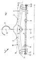
- a clothes hanger 1 for hanging articles of clothing has a first and a second hanger arm 2, 3 for receiving a clothing item in the shoulder area 4.
- a symmetry line 12 is defined as a vertical at the junction of hanger 1 and hooks 5.
- the hanger arms 2, 3 are relative to the centrally arranged attachment hooks 5 laterally to this mirror image (to the line of symmetry 12), preferably in the same size, arranged.
- the dimensioning of the hanger arms 2, 3 itself essentially corresponds to a specified dimension for a shoulder region 4 of a clothing item.
- the hanger 1 is - starting from the bracket arms 2, 3 - beyond the shoulder region 4 by means of a first bracket arm 2 associated first support rod 10 and a second bracket arm 3 associated second support rod 11 in its length changeable.
- the horizontal 14 intersects the fastening hook 5 in the connection point of hanger 1 and fastening hooks 5 and the intersection of the axes 13.
- the axes 13 are formed straight or curved in their course.
- each bail arm 2, 3 each has a first support rod 10 (assigned to the first bail arm 2) and a second support rod 11 (assigned to the second bail arm 3).
- the support rods 10, 11 are preferably the same size and serve to accommodate sleeves of a clothing item.
- the sleeves are supported and the item of clothing is recorded in shape and wrinkle-free.
- each bail arm 2, 3 of the hanger 1 each have a telescopically adjustable in length support bar 10, 11.
- the hanger arms 2, 3 are preferably designed as hollow profiles and receive the supporting rods 10, 11 mounted in the interior.
- the hollow profile as a closed or open, for example, downwardly open, the support rods 10, 11 receiving, hollow profile executable.
- the telescopic support rods 10, 11 end in the respective Bail arm 2, 3, for example releasably positively, stored and are adjustable at the free end over the shoulder region 4 addition to the desired telescopic length by pulling out.
- the respective length extending beyond the shoulder area 4 is approximately 150-300 mm for each support bar 10, 11 and approximately 450-600 mm for a long-sleeved item of clothing.
- the telescopically formed support rods 10, 11 are thus up to a length of about 600 mm from the respective bail arm 2, 3 extendable and in the respective bail arm 2, 3 inserted back.
- the support rods 10, 11 are further arbitrarily adjustable to intervening lengths and by the individual telescopic members of the support rods 10, 11 a self-locking in the respective length is guaranteed.
- the axes of the support rods 10, 11 are aligned in a preferred embodiment with the respective axis 13 of the hanger arms 2, 3.
- the hanger arms 2, 3 are made of materials such as wood, metal or preferably a plastic executable.
- the support rods 10, 11 are made of a rigid material, preferably a tubular metal, executable.
- a hanger 1 has a crossbar 6 arranged below the hanger arms 2, 3.
- the axis of the crossbar 6 is parallel to Horizontal 14 arranged.
- the crossbar 6 is fixed by means of a tab 7 on the bracket arms 2, 3.
- On the cross bar 6 at least one clamping device 8 is arranged in the axial direction slidably.
- a plurality of such clamping devices 8 are arranged, which serve the releasable fixation of skirts and / or pants.
- hook-shaped holders 9 which are arranged open at the top, are fixedly arranged for the reception of preferably skirts and / or pants in the region of the transverse bar 6 or the respective tongue 7.
- the crossbar 6 is preferably formed as a hollow profile has in the interior at least one longitudinally displaceably mounted in the axial direction of the cross bar 6 first support rod 15.
- the crossbar 6 is additionally formed with a second support rod 16.
- This support rod 16 is analogous to the support rod 15 is formed and stored.
- Both support rods 15, 16 are arranged mirror-symmetrically to the line of symmetry 12 and laterally outwardly in the axial direction, so that the transverse rod 6 can be extended in the axial direction.
- the support rods 15, 16 are preferably detachably fixable at least in the end positions and traceable in their axial length on the administratlot.
- the support rods 15, 16 in the extended position self-locking or with fixing in functional connection.
- the extendable in the axial direction support rods 15, 16 each have a hook-shaped receptacle 22 at the free ends.
- This receptacle 22 is for example a circumferential groove or an upwardly open hook for receiving the loops of a clothing item.
- This training is advantageous to fix a garment, such as a skirt in its waistband, taut on the crossbar releasably.
- FIG. 3 a first embodiment of a hanger 1 shown.
- a hanger 1 for clothing items with shoulder pads or for broad (transversely to the shoulder area 4) trained shoulders in the shoulder region 4 on the first and second bracket arms 2,3 mirror image of the line of symmetry 12 each one attachment element 24 detachably arranged.
- the attachment elements 24 are preferably end-side in the direction of the line of symmetry 12 - adapted to the bracket arms 2.3 - relatively narrow.
- the attachment elements 24 are preferably wider in their region facing away from the line of symmetry 12, so that the widest possible support for the shoulder pads can be achieved.
- each attachment element 4 for example, from the top of the respective arm 2.3 detachable by a clamp connection can be arranged.
- each attachment element 4 is arranged axially parallel to the axis 13 in the direction of double arrow 26 slidably.
- a guide is preferably provided, arranged on the respective bow arm 2, 3 and on the inside of the respective attachment element 24.
- such a guide can be arranged as at least one tab 25 on the attachment elements 24, as exemplified in Fig. 3 with two tabs 25 is shown.
- each tab 25 when pushed (double arrow 26) surrounds the corresponding bail arm 2, 3 (in Fig. 3 only the first bail arm 2 is shown) in the lower region and is in the end position on the bail arm 2,3 self-locking fixable.
- Each attachment element 24 is preferably designed as a downwardly open hollow profile.
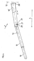
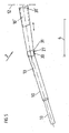
- FIGS. 4 and 5 are second and third developments based on at least FIG. 1 shown.
- the support rods 10,11 are mounted and arranged telescopically over the shoulder portion 4 addition.
- support rods 10,11 are, for example, to reduce the space required for hanging a clothing item or the support rods 10,11 better the item of clothing, especially the sleeves to adapt, the support rods 10,11 in their inclination angle to the axis 13 of the hanger arms 2.3 changeable.
- This aligned in a first position the Axes of the support rods 10,11 - such as in FIG. 2 shown - with the axis 13 and in a second position intersect these axes of the support rods 10,11 the axis 13.
- FIGS. 4 and only the first bail arm 2 with the first support bar 10 is shown.
- each hinge axis 27 releasably form-fitting manner and is exemplified below - based on the first bail arm 2 and the first support bar 10 - are explained in more detail in two variants.
- the first embodiment of a hinge axis 27 is in FIG. 4 shown.
- the hinge axis 27 is formed such that the first bail arm 2 has at least one respective groove 29 on the side surfaces.
- a bolt 28 is arranged at the ends in the direction of the first bail arm 2 on both sides.
- the bolts 28' are guided below the side surfaces of the bail arm 2. Now, if the support rod 10 is extended over the shoulder portion 4, that is extended, the bolts 28 slide below the side surface along until reaching the respective groove 29 and snap into each of the associated groove 29 on both sides one.
- the support bar 10 tilts around the hinge axis 27 formed by the groove 29 and the bolt 28, so that the axis of the support bar 10 intersects the axis 13 (bail arm 2). If the state is canceled, the support rod 10 is moved about the hinge axis 27, so that the axis of the support rod 10 is aligned with the axis 13 and the support rod 10 is pushed into the bail arm 2 to the end position (support rod 10 ').
- the bolts 28 slide simultaneously from the grooves 29 and below the side surfaces of the bail arm 2 along.
- the second embodiment of the hinge axis 27 is in FIG. 5 shown.
- the hinge axis 27 is preferably releasably form-fitting manner, such that the first bail arm 2 has an end below the side walls an angled to the axis 13 guide 30.
- a stop 31 is arranged at the end (in the direction of the first bail arm 2).
- the support arm 10 'with stop 31' in the bail arm 2 is added.
- the support rod 10 is extended over the shoulder area 4, that is extended, then the support arm 10 slides with stop 31 in the bail arm 2 along until reaching the guide 30, which positions the stopper 31. Since there is sufficient space within the first bail arm 2, the support bar 10 tilts around the hinge axis 27 formed from stop 31 and guide 30, so that the axis of the support bar 10 intersects the axis 13 (bail arm 2).
- the support rod 10 is moved about the hinge axis 27, such that the axis of the support rod 10 is aligned with the axis 13 and the support rod 10 is inserted into the bail arm 2 to the end position (support rod 10 ').
- the axes of the support rods 10, 11 can be pivoted about an articulation axis 27 by an arrangement aligned with the axis 13 of the clamp arms 2, 3 in an arrangement intersecting the axis 13 of the clamp arms 2, 3.
- the hanger arms 2,3 and the support rods 10,11 are preferably downwardly open hollow profiles.
Landscapes
- Holders For Apparel And Elements Relating To Apparel (AREA)
Claims (9)
- Cintre (1) à vêtements servant à suspendre des articles d'habillement et présentant un premier et un deuxième bras de cintre (2, 3) destinés à reprendre les parties d'épaule d'un article d'habillement, ainsi qu'un crochet de fixation (5) disposé au milieu et permettant de relier de manière libérable le cintre (1) à vêtements à un moyen de support, une ligne de symétrie (12) étant définie dans la direction verticale à l'emplacement de liaison du premier et du deuxième bras de cintre (2, 3) et du crochet de fixation (5), le premier et le deuxième bras de cintre (2, 3) étant disposés symétriquement et pouvant être prolongés au-delà de la partie d'épaule (4), chacun au moyen d'un premier barreau porteur (10) associé au premier bras de cintre (2) et d'un deuxième barreau porteur (11) associé au deuxième bras de cintre (3),
caractérisé en ce que
les barreaux porteurs (10, 11) présentent des éléments télescopiques, sont télescopiques et peuvent être extraits sur une longueur d'environ 600 mm, les barreaux porteurs (10, 11) pouvant être ajustés à volonté à des longueurs intermédiaires et un autoblocage dans la longueur particulière étant assuré par les différents éléments télescopiques des barreaux porteurs (10, 11). - Cintre à vêtements selon la revendication 1, caractérisé en ce que les barreaux porteurs (10, 11) sont montés à l'intérieur du premier et du deuxième bras de cintre (2, 3) et sont disposés télescopiquement dans la partie (4) des épaules.
- Cintre à vêtements selon la revendication 1, caractérisé en ce que les barreaux porteurs (10, 11) sont reliés chacun par une première articulation de rotation (18) aux bras de cintre (2, 3) respectifs et peuvent être rabattus sur la partie des épaules (4).
- Cintre à vêtements selon l'une des revendications précédentes, caractérisé en ce qu'une extrémité des barreaux porteurs (10, 11) sont reliés de manière libérable et en correspondance géométrique à chacun des bras de cintre (2, 3).
- Cintre à vêtements selon l'une des revendications précédentes, caractérisé en ce qu'une tringle transversale (6) est disposée sur le cintre (1) à vêtements en dessous des bras de cintre (2, 3) et en ce qu'au moins une tringle porteuse (15, 16) peut coulisser longitudinalement dans la direction de l'axe de la tringle transversale (6) à l'intérieur de la tringle transversale (6).
- Cintre à vêtements selon la revendication 5, caractérisé en ce que les tringles porteuses (15, 16) présentent à leur extrémité libre un support (22) en forme de crochet.
- Cintre à vêtements selon l'une des revendications précédentes, caractérisé en ce que dans la partie (4) des épaules, un élément d'appui (24) peut être disposé de manière libérable sur le premier et le deuxième bras de cintre (2, 3), symétriquement par rapport à la ligne de symétrie (12).
- Cintre à vêtements selon l'une des revendications précédentes, caractérisé en ce que les bras de cintre (2, 3) présentent des axes (13) disposés symétriquement par rapport à la ligne de symétrie (12) et forment un angle (α, α') α = α' < 90° par rapport à l'horizontale.
- Cintre à vêtements selon l'une des revendications précédentes, caractérisé en ce qu'à l'extérieur de la partie (4) des épaules, les axes des barreaux porteurs (10, 11) peuvent tous deux pivoter autour d'un axe d'articulation (27) depuis une position alignée sur l'axe (13) des bras de cintre (2, 3) jusque dans une position qui coupe l'axe (13) des bras de support (2, 3) .
Applications Claiming Priority (3)
| Application Number | Priority Date | Filing Date | Title |
|---|---|---|---|
| DE10101448A DE10101448A1 (de) | 2001-01-15 | 2001-01-15 | Kleiderbügel |
| DE10101448 | 2001-01-15 | ||
| PCT/EP2002/000271 WO2002067734A2 (fr) | 2001-01-15 | 2002-01-14 | Cintre |
Publications (2)
| Publication Number | Publication Date |
|---|---|
| EP1379152A2 EP1379152A2 (fr) | 2004-01-14 |
| EP1379152B1 true EP1379152B1 (fr) | 2008-12-03 |
Family
ID=7670525
Family Applications (1)
| Application Number | Title | Priority Date | Filing Date |
|---|---|---|---|
| EP02729923A Expired - Lifetime EP1379152B1 (fr) | 2001-01-15 | 2002-01-14 | Cintre |
Country Status (4)
| Country | Link |
|---|---|
| EP (1) | EP1379152B1 (fr) |
| AT (1) | ATE415842T1 (fr) |
| DE (2) | DE10101448A1 (fr) |
| WO (1) | WO2002067734A2 (fr) |
Family Cites Families (10)
| Publication number | Priority date | Publication date | Assignee | Title |
|---|---|---|---|---|
| US1809561A (en) * | 1930-08-28 | 1931-06-09 | Muller Elisabeth | Foldable garment hanger |
| GB494210A (en) * | 1937-11-12 | 1938-10-21 | Anne Alice Lancaster | Improvements relating to garment hangers |
| FR939781A (fr) * | 1947-01-17 | 1948-11-24 | Porte-manteau extensible | |
| US2620102A (en) * | 1950-02-27 | 1952-12-02 | Fred H Bremer | Extensible garment hanger |
| US2722351A (en) * | 1953-06-09 | 1955-11-01 | Dyer Francis John | Garment hanger |
| CH456084A (de) * | 1966-05-04 | 1968-05-15 | Knuchel Erwin | Kleiderbügel |
| US3695492A (en) * | 1970-06-22 | 1972-10-03 | Helen Sheba | Adjustable garment shape-retaining hanger |
| DE2625958A1 (de) * | 1976-06-10 | 1977-12-22 | Peter Weber | Kleiderbuegel mit in einen aufhaengeteil einschiebbaren traegerstuecken |
| DE19650210A1 (de) * | 1996-12-04 | 1998-06-10 | Hanna Demel | Stufenlos verstellbarer Kleiderbügel zum Trocknen von Strick- und Wirkwaren |
| DE20100606U1 (de) * | 2001-01-15 | 2001-04-12 | Hechler, Peter, 64397 Modautal | Kleiderbügel |
-
2001
- 2001-01-15 DE DE10101448A patent/DE10101448A1/de not_active Withdrawn
-
2002
- 2002-01-14 DE DE50213079T patent/DE50213079D1/de not_active Expired - Lifetime
- 2002-01-14 WO PCT/EP2002/000271 patent/WO2002067734A2/fr not_active Ceased
- 2002-01-14 AT AT02729923T patent/ATE415842T1/de active
- 2002-01-14 EP EP02729923A patent/EP1379152B1/fr not_active Expired - Lifetime
Also Published As
| Publication number | Publication date |
|---|---|
| WO2002067734A3 (fr) | 2002-10-31 |
| ATE415842T1 (de) | 2008-12-15 |
| EP1379152A2 (fr) | 2004-01-14 |
| DE10101448A1 (de) | 2002-07-18 |
| WO2002067734A2 (fr) | 2002-09-06 |
| DE50213079D1 (de) | 2009-01-15 |
Similar Documents
| Publication | Publication Date | Title |
|---|---|---|
| EP0339053B1 (fr) | Porte-vetements multiple articule | |
| EP2913432B1 (fr) | Châssis pour séchoir à linge | |
| EP1627948A1 (fr) | Séchoir à linge | |
| DE4007320A1 (de) | Universal-kleiderbuegel | |
| DE202016008147U1 (de) | Trocken- oder Wäscheständer | |
| EP0882419B1 (fr) | Cintre pour vêtements | |
| WO2002067734A2 (fr) | Cintre | |
| EP2801301A2 (fr) | Cintre | |
| DE10305746B4 (de) | Wäscheständer | |
| EP1881102A2 (fr) | Chassis pour séchoir à linge | |
| DE29515167U1 (de) | Transportbügel | |
| DE20100606U1 (de) | Kleiderbügel | |
| DE102019122647B3 (de) | Standwäschetrockner | |
| DE102008010159B4 (de) | Vorrichtung zum Trocknen von Wäsche | |
| DE102023130358B4 (de) | Wäschehalter | |
| DE4231126A1 (de) | Vorrichtung zum Aufhängen vorzugsweise langer Kleidungsstücke | |
| DE102017104112A1 (de) | Trocken- oder Wäscheständer | |
| DE3900891A1 (de) | Schwenk- und drehbarer mehrfachkleiderbuegel | |
| DE102017102342A1 (de) | Trocken- oder Wäscheständer | |
| DE102023112843A1 (de) | Trocken- oder Wäscheständer | |
| DE29515437U1 (de) | Transportbügel | |
| DE9212412U1 (de) | Vorrichtung zum Aufhängen vorzugsweise langer Kleidungsstücke | |
| DE102006042491B3 (de) | Wäschetrocknungsgestell | |
| DE7421364U (de) | Scheren-Wäschetrockner | |
| DE9102734U1 (de) | Zusammenklappbarer Einhand-Kleiderbügel |
Legal Events
| Date | Code | Title | Description |
|---|---|---|---|
| PUAI | Public reference made under article 153(3) epc to a published international application that has entered the european phase |
Free format text: ORIGINAL CODE: 0009012 |
|
| 17P | Request for examination filed |
Effective date: 20031114 |
|
| AK | Designated contracting states |
Kind code of ref document: A2 Designated state(s): AT BE CH CY DE DK ES FI FR GB GR IE IT LI LU MC NL PT SE TR |
|
| AX | Request for extension of the european patent |
Extension state: AL LT LV MK RO SI |
|
| 17Q | First examination report despatched |
Effective date: 20070712 |
|
| GRAP | Despatch of communication of intention to grant a patent |
Free format text: ORIGINAL CODE: EPIDOSNIGR1 |
|
| GRAS | Grant fee paid |
Free format text: ORIGINAL CODE: EPIDOSNIGR3 |
|
| GRAA | (expected) grant |
Free format text: ORIGINAL CODE: 0009210 |
|
| AK | Designated contracting states |
Kind code of ref document: B1 Designated state(s): AT BE CH CY DE DK ES FI FR GB GR IE IT LI LU MC NL PT SE TR |
|
| REG | Reference to a national code |
Ref country code: GB Ref legal event code: FG4D Free format text: NOT ENGLISH |
|
| REG | Reference to a national code |
Ref country code: CH Ref legal event code: EP |
|
| REG | Reference to a national code |
Ref country code: IE Ref legal event code: FG4D Free format text: LANGUAGE OF EP DOCUMENT: GERMAN |
|
| REF | Corresponds to: |
Ref document number: 50213079 Country of ref document: DE Date of ref document: 20090115 Kind code of ref document: P |
|
| REG | Reference to a national code |
Ref country code: CH Ref legal event code: NV Representative=s name: ISLER & PEDRAZZINI AG |
|
| PG25 | Lapsed in a contracting state [announced via postgrant information from national office to epo] |
Ref country code: ES Free format text: LAPSE BECAUSE OF FAILURE TO SUBMIT A TRANSLATION OF THE DESCRIPTION OR TO PAY THE FEE WITHIN THE PRESCRIBED TIME-LIMIT Effective date: 20090314 |
|
| NLV1 | Nl: lapsed or annulled due to failure to fulfill the requirements of art. 29p and 29m of the patents act | ||
| PG25 | Lapsed in a contracting state [announced via postgrant information from national office to epo] |
Ref country code: NL Free format text: LAPSE BECAUSE OF FAILURE TO SUBMIT A TRANSLATION OF THE DESCRIPTION OR TO PAY THE FEE WITHIN THE PRESCRIBED TIME-LIMIT Effective date: 20081203 Ref country code: FI Free format text: LAPSE BECAUSE OF FAILURE TO SUBMIT A TRANSLATION OF THE DESCRIPTION OR TO PAY THE FEE WITHIN THE PRESCRIBED TIME-LIMIT Effective date: 20081203 |
|
| REG | Reference to a national code |
Ref country code: IE Ref legal event code: FD4D |
|
| PG25 | Lapsed in a contracting state [announced via postgrant information from national office to epo] |
Ref country code: IE Free format text: LAPSE BECAUSE OF FAILURE TO SUBMIT A TRANSLATION OF THE DESCRIPTION OR TO PAY THE FEE WITHIN THE PRESCRIBED TIME-LIMIT Effective date: 20081203 |
|
| PG25 | Lapsed in a contracting state [announced via postgrant information from national office to epo] |
Ref country code: SE Free format text: LAPSE BECAUSE OF FAILURE TO SUBMIT A TRANSLATION OF THE DESCRIPTION OR TO PAY THE FEE WITHIN THE PRESCRIBED TIME-LIMIT Effective date: 20090303 Ref country code: PT Free format text: LAPSE BECAUSE OF FAILURE TO SUBMIT A TRANSLATION OF THE DESCRIPTION OR TO PAY THE FEE WITHIN THE PRESCRIBED TIME-LIMIT Effective date: 20090504 Ref country code: MC Free format text: LAPSE BECAUSE OF NON-PAYMENT OF DUE FEES Effective date: 20090131 |
|
| PLBE | No opposition filed within time limit |
Free format text: ORIGINAL CODE: 0009261 |
|
| STAA | Information on the status of an ep patent application or granted ep patent |
Free format text: STATUS: NO OPPOSITION FILED WITHIN TIME LIMIT |
|
| PG25 | Lapsed in a contracting state [announced via postgrant information from national office to epo] |
Ref country code: DK Free format text: LAPSE BECAUSE OF FAILURE TO SUBMIT A TRANSLATION OF THE DESCRIPTION OR TO PAY THE FEE WITHIN THE PRESCRIBED TIME-LIMIT Effective date: 20081203 |
|
| 26N | No opposition filed |
Effective date: 20090904 |
|
| GBPC | Gb: european patent ceased through non-payment of renewal fee |
Effective date: 20090303 |
|
| PG25 | Lapsed in a contracting state [announced via postgrant information from national office to epo] |
Ref country code: BE Free format text: LAPSE BECAUSE OF NON-PAYMENT OF DUE FEES Effective date: 20090131 |
|
| PG25 | Lapsed in a contracting state [announced via postgrant information from national office to epo] |
Ref country code: GB Free format text: LAPSE BECAUSE OF NON-PAYMENT OF DUE FEES Effective date: 20090303 |
|
| PG25 | Lapsed in a contracting state [announced via postgrant information from national office to epo] |
Ref country code: GR Free format text: LAPSE BECAUSE OF FAILURE TO SUBMIT A TRANSLATION OF THE DESCRIPTION OR TO PAY THE FEE WITHIN THE PRESCRIBED TIME-LIMIT Effective date: 20090304 |
|
| PG25 | Lapsed in a contracting state [announced via postgrant information from national office to epo] |
Ref country code: IT Free format text: LAPSE BECAUSE OF FAILURE TO SUBMIT A TRANSLATION OF THE DESCRIPTION OR TO PAY THE FEE WITHIN THE PRESCRIBED TIME-LIMIT Effective date: 20081203 |
|
| REG | Reference to a national code |
Ref country code: DE Ref legal event code: R081 Ref document number: 50213079 Country of ref document: DE Owner name: SCHLINDWEIN, IRMGARD, DE Free format text: FORMER OWNER: HECHLER, PETER, 64397 MODAUTAL, DE Effective date: 20110217 |
|
| PG25 | Lapsed in a contracting state [announced via postgrant information from national office to epo] |
Ref country code: LU Free format text: LAPSE BECAUSE OF NON-PAYMENT OF DUE FEES Effective date: 20090114 |
|
| PG25 | Lapsed in a contracting state [announced via postgrant information from national office to epo] |
Ref country code: TR Free format text: LAPSE BECAUSE OF FAILURE TO SUBMIT A TRANSLATION OF THE DESCRIPTION OR TO PAY THE FEE WITHIN THE PRESCRIBED TIME-LIMIT Effective date: 20081203 |
|
| PG25 | Lapsed in a contracting state [announced via postgrant information from national office to epo] |
Ref country code: CY Free format text: LAPSE BECAUSE OF FAILURE TO SUBMIT A TRANSLATION OF THE DESCRIPTION OR TO PAY THE FEE WITHIN THE PRESCRIBED TIME-LIMIT Effective date: 20081203 |
|
| REG | Reference to a national code |
Ref country code: CH Ref legal event code: PUE Owner name: IRMGARD SCHLINDWEIN Free format text: HECHLER, PETER#BIEBERAUER STRASSE 42#D-64397 MODAUTAL (DE) -TRANSFER TO- IRMGARD SCHLINDWEIN#AM BREILINGSWEG 10#76709 KRONAU (DE) |
|
| REG | Reference to a national code |
Ref country code: FR Ref legal event code: TP Owner name: IRMGARD SCHLINDWEIN, DE Effective date: 20120515 |
|
| REG | Reference to a national code |
Ref country code: AT Ref legal event code: PC Ref document number: 415842 Country of ref document: AT Kind code of ref document: T Owner name: SCHLINDWEIN IRMGARD, DE Effective date: 20121022 |
|
| PGFP | Annual fee paid to national office [announced via postgrant information from national office to epo] |
Ref country code: AT Payment date: 20150129 Year of fee payment: 14 |
|
| REG | Reference to a national code |
Ref country code: FR Ref legal event code: PLFP Year of fee payment: 15 |
|
| REG | Reference to a national code |
Ref country code: AT Ref legal event code: MM01 Ref document number: 415842 Country of ref document: AT Kind code of ref document: T Effective date: 20160114 |
|
| PG25 | Lapsed in a contracting state [announced via postgrant information from national office to epo] |
Ref country code: AT Free format text: LAPSE BECAUSE OF NON-PAYMENT OF DUE FEES Effective date: 20160114 |
|
| REG | Reference to a national code |
Ref country code: FR Ref legal event code: PLFP Year of fee payment: 16 |
|
| PGFP | Annual fee paid to national office [announced via postgrant information from national office to epo] |
Ref country code: CH Payment date: 20170125 Year of fee payment: 16 Ref country code: FR Payment date: 20170124 Year of fee payment: 16 |
|
| REG | Reference to a national code |
Ref country code: CH Ref legal event code: PL |
|
| PG25 | Lapsed in a contracting state [announced via postgrant information from national office to epo] |
Ref country code: FR Free format text: LAPSE BECAUSE OF NON-PAYMENT OF DUE FEES Effective date: 20180131 |
|
| REG | Reference to a national code |
Ref country code: FR Ref legal event code: ST Effective date: 20180928 |
|
| PG25 | Lapsed in a contracting state [announced via postgrant information from national office to epo] |
Ref country code: LI Free format text: LAPSE BECAUSE OF NON-PAYMENT OF DUE FEES Effective date: 20180131 Ref country code: CH Free format text: LAPSE BECAUSE OF NON-PAYMENT OF DUE FEES Effective date: 20180131 |
|
| PGFP | Annual fee paid to national office [announced via postgrant information from national office to epo] |
Ref country code: DE Payment date: 20190122 Year of fee payment: 18 |
|
| REG | Reference to a national code |
Ref country code: DE Ref legal event code: R119 Ref document number: 50213079 Country of ref document: DE |
|
| PG25 | Lapsed in a contracting state [announced via postgrant information from national office to epo] |
Ref country code: DE Free format text: LAPSE BECAUSE OF NON-PAYMENT OF DUE FEES Effective date: 20200801 |