EP1379413B1 - Balai d'essuie-glace pour le nettoyage de vitres, en particulier de vehicules automobiles - Google Patents
Balai d'essuie-glace pour le nettoyage de vitres, en particulier de vehicules automobiles Download PDFInfo
- Publication number
- EP1379413B1 EP1379413B1 EP02714067A EP02714067A EP1379413B1 EP 1379413 B1 EP1379413 B1 EP 1379413B1 EP 02714067 A EP02714067 A EP 02714067A EP 02714067 A EP02714067 A EP 02714067A EP 1379413 B1 EP1379413 B1 EP 1379413B1
- Authority
- EP
- European Patent Office
- Prior art keywords
- strip
- wiper
- wiper blade
- mass body
- extension
- Prior art date
- Legal status (The legal status is an assumption and is not a legal conclusion. Google has not performed a legal analysis and makes no representation as to the accuracy of the status listed.)
- Expired - Lifetime
Links
- 239000011521 glass Substances 0.000 title claims 8
- 238000004140 cleaning Methods 0.000 title claims 2
- 239000000463 material Substances 0.000 claims description 24
- 238000006073 displacement reaction Methods 0.000 claims description 7
- 230000010355 oscillation Effects 0.000 claims description 4
- 230000008719 thickening Effects 0.000 claims description 3
- 230000033001 locomotion Effects 0.000 description 9
- 230000005484 gravity Effects 0.000 description 4
- 238000009826 distribution Methods 0.000 description 3
- 238000001125 extrusion Methods 0.000 description 3
- 230000005540 biological transmission Effects 0.000 description 1
- 244000145845 chattering Species 0.000 description 1
- 239000002131 composite material Substances 0.000 description 1
- 238000010276 construction Methods 0.000 description 1
- 230000007547 defect Effects 0.000 description 1
- 230000000694 effects Effects 0.000 description 1
- 239000013013 elastic material Substances 0.000 description 1
- 230000008029 eradication Effects 0.000 description 1
- 238000009434 installation Methods 0.000 description 1
- 238000000034 method Methods 0.000 description 1
- 230000002787 reinforcement Effects 0.000 description 1
- 230000000284 resting effect Effects 0.000 description 1
- 239000000126 substance Substances 0.000 description 1
- 238000009827 uniform distribution Methods 0.000 description 1
Images


Classifications
-
- B—PERFORMING OPERATIONS; TRANSPORTING
- B60—VEHICLES IN GENERAL
- B60S—SERVICING, CLEANING, REPAIRING, SUPPORTING, LIFTING, OR MANOEUVRING OF VEHICLES, NOT OTHERWISE PROVIDED FOR
- B60S1/00—Cleaning of vehicles
- B60S1/02—Cleaning windscreens, windows or optical devices
- B60S1/04—Wipers or the like, e.g. scrapers
- B60S1/32—Wipers or the like, e.g. scrapers characterised by constructional features of wiper blade arms or blades
- B60S1/38—Wiper blades
- B60S1/3848—Flat-type wiper blade, i.e. without harness
- B60S1/3874—Flat-type wiper blade, i.e. without harness with a reinforcing vertebra
- B60S1/3875—Flat-type wiper blade, i.e. without harness with a reinforcing vertebra rectangular section
- B60S1/3879—Flat-type wiper blade, i.e. without harness with a reinforcing vertebra rectangular section placed in side grooves in the squeegee
-
- B—PERFORMING OPERATIONS; TRANSPORTING
- B60—VEHICLES IN GENERAL
- B60S—SERVICING, CLEANING, REPAIRING, SUPPORTING, LIFTING, OR MANOEUVRING OF VEHICLES, NOT OTHERWISE PROVIDED FOR
- B60S1/00—Cleaning of vehicles
- B60S1/02—Cleaning windscreens, windows or optical devices
- B60S1/04—Wipers or the like, e.g. scrapers
- B60S1/32—Wipers or the like, e.g. scrapers characterised by constructional features of wiper blade arms or blades
- B60S1/38—Wiper blades
- B60S1/3806—Means, or measures taken, for influencing the aerodynamic quality of the wiper blades
- B60S1/3808—Spoiler integral with the squeegee
-
- B—PERFORMING OPERATIONS; TRANSPORTING
- B60—VEHICLES IN GENERAL
- B60S—SERVICING, CLEANING, REPAIRING, SUPPORTING, LIFTING, OR MANOEUVRING OF VEHICLES, NOT OTHERWISE PROVIDED FOR
- B60S1/00—Cleaning of vehicles
- B60S1/02—Cleaning windscreens, windows or optical devices
- B60S1/04—Wipers or the like, e.g. scrapers
- B60S1/32—Wipers or the like, e.g. scrapers characterised by constructional features of wiper blade arms or blades
- B60S1/38—Wiper blades
- B60S2001/3812—Means of supporting or holding the squeegee or blade rubber
Definitions
- the support element over the entire swept by the wiper blade wiping field to ensure the most uniform distribution of the wiper blade outgoing wiper blade contact pressure on the disc.
- the ends of the wiper blade fully applied to the disc wiper blade are loaded by the then strained Tragelment to the disc, even if the radii of curvature of spherically curved vehicle windows change at each wiper position.
- the curvature of the wiper blade must therefore be somewhat stronger than the strongest curvature measured in the wiping field on the pane to be wiped.
- the support element thus replaced the known, elaborate mounting bracket construction with two arranged in the wiper strip, the transverse reinforcement of the rubber-elastic wiper strip serving spring rails (DE-OS 15 05 397).
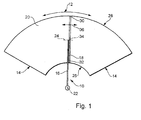
- the wiper blade 18 is pivotally connected to the free end of the wiper arm 16 so that the wiper blade can swing about an axis 24 oriented approximately parallel to the disk axis and can adapt to the course of the disk surface, which deviates from the swinging plane of the wiper arm because of their shape.
- the wiping field limitation results from the two pendulum reversal positions 14 and the wiper radii 26 and 28, of which the outer, larger radius 28 through the pendulum axis remote end 30 of the wiper blade 18 and the inner, smaller radius 26 through the pendulum axis near end 32 of the wiper blade 18 are effected.
- US-A-2,794,203 has disclosed a wiper blade with a support bracket system which has a wind vane that is more or less deflected against a spring depending on the impact velocity of the incident airstream and thus removed from the airstream.
- the vibration behavior of the wiper blade can not be positively influenced.
- the height of the supporting element by the low-building support element can be kept small.
- the length of the wiper blade is limited to the necessary level for wiping.
- the support member has two spaced apart from each other and parallel to each other, arranged in a common plane spring rails wherein the wiper strip extends at least over part of its length with an extension through the gap between the two spring rails. At this extension can then be arranged in a simple manner, at least one mass body.
- the mass body is strip-like and extends in the longitudinal direction of the support element, this can be provided according to the respective criteria with a corresponding length which corresponds at most to the wiper blade length. In this way it is possible to adapt the available mass to the requirements, without the wiper blade has a larger space requirement.
- Windabweisang For a variety of applications in which the demand for a Windabschreibance must be taken into account is advantageously formed of the mass body as Windabschreibang.
- the mass body has an at least approximately triangular cross section or if the mass body seen in cross section at its remote from the extension, free end with a thickening is provided.
- the wind deflector strip is made of a different material than the wiper strip manufactured jointly with it and fixedly connected to it.
- the choice of a material is possible, both for the wiper strip or for the Fulfillment of these requirements is particularly suitable, while also the concerns of the mass body or the wind deflector can be taken into account in a special way.
- the wiper strip has a body that merges on its side facing away from the disc on the extension in the wind deflector and further on the the disk-facing side of the base body a can be applied to the disc, strip-like, made of a different material together with the base wiper lip is arranged, which is connected via a web bar with this.
- a further embodiment of the invention provides that on the extension designed as an elongated hollow body Windabweisang is formed in the cavity of which is connected to the extension, freely in the direction of displacement of the wiper blade movable mass body.
- the extension of the wiper strip on the upper band side of the support element in a strip-like base strip. goes over, with which the Windabweismann is connected via an articulated strip formed by lateral edge-open longitudinal grooves.
- the support member thus comprises two in a common, lying approximately parallel to the disk plane spring bands, which lie in their associated, bounded by the base strip upwards grooves. The distance between the mutually facing inner edges of the Spring strips allows the passage of the wiper strip through the support element.
- the hinge bar allows the necessary mobility of the mass body in the direction of displacement of the wiper blade, with their dimensions oriented to the requirements with respect to the required oscillation frequency of the mass body.
- the extension of the wiper strip on the upper hinge side of the support element merges into a strip-like base strip with which the existing of another material, together with the wiper strip hollow body is firmly connected via a formed by laterally open longitudinal grooves hinge strip, can be used for the choice of material for the hollow body and a substance that is particularly advantageous for this, for the fulfillment of the demands made on the wiper strip tasks, however, unsuitable.
- the mass body consists of a different material than the wiper strip which is manufactured together with it and is firmly connected.
- the wiper strip is arranged.
- FIG. 2 shows a side view of a wiper blade according to the invention
- FIG. 3 shows a plan view of the wiper blade according to FIG. 2 with indicated wiper arm
- FIG 4 shows the arrangement according to FIG. 4 with the indication of the oscillating end positions of a mass body arranged on the wiper blade
- FIG. 6 shows another embodiment of the mass body present on the wiper blade
- FIG. 7 shows the arrangement according to FIG. 4 with a further embodiment of the mass body present on the wiper blade
- FIG. 8 shows the arrangement according to FIG. 4 with a two-component wiper strip
- FIG. 9 shows the arrangement according to FIG. 4 with a multi-material wiper strip
- FIG. 10 shows the arrangement according to FIG 4 at wel
- FIG. 11 shows the arrangement according to FIG.
- FIG. 12 shows the arrangement according to FIG. 10, in which the wind deflector strip is made of a different material than the one shown in FIG the wiper strip is manufactured and
- FIG. 13 shows the arrangement according to FIG. 12 in which the mass body is also made of a different material than the wiper strip.
- a wiper blade 40 of a first embodiment of the invention shown in FIGS. 2 and 3 has a strip-like, elongated, spring-elastic support element 42 with two spring rails 41 arranged at a distance from one another and parallel to one another and arranged in a common plane.
- a connecting device 44 is arranged in its middle section, with the aid of which the wiper blade 40 is guided by a wiper arm 48, which is guided on the body of a motor vehicle and oscillates about a pendulum axis 45 can be releasably connected ( Figure 2 and 3).
- an elongate, rubber-elastic wiper strip 46 is held along the longitudinal axis.
- a hinge pin 50 belonging to the connecting device 44 of the wiper blade 40 is provided as counter-connection means, which in the sense of a joint cooperates with a bearing point present in the connection device 44.
- the wiper arm 48 and thus also the wiper blade 40 are loaded in the direction of the arrow 52 to be wiped disc 43, the surface to be wiped is indicated in Figure 2 by the dotted line 54.
- the dot-dash line 54 is intended to represent the strongest curvature of the disk surface, it is clearly evident that the longitudinal curvature of the still unloaded wiper blade resting against the disk with its ends is greater than the maximum disk curvature. It has - unloaded - so opposite the disc a concave course.
- the wiper strip 46 On the convex outer upper side 43 of the support member 42 sits the connecting device 44 and on the concave inner bottom 49 of the support member 42 is the wiper strip 46 with its the moping task Wiper lip 56 arranged. Under the contact pressure (arrow 52), the wiper blade 40 with its wiper lip 56 lays against the disk surface 50 over its entire length and changes into a working position which approximates the extended position. In this case, a tension builds up in the band-like, resilient support element 42, which ensures a proper contact of the wiper strip 46 or its wiper lip 56 over its entire length on the vehicle window 54 and thus for a correct distribution of the contact pressure.
- the wiper blade 40 is provided with a strip-like mass body 60 which extends in the longitudinal direction of the support member 42.
- the mass body 60 is arranged in the area of the upper belt surface 43 of the support element 42 facing away from the disk.
- the support member 42 has in the embodiment two spaced apart and parallel to each other, arranged in a common plane spring rails 41, which lie in laterally open edge longitudinal grooves 62 of the wiper strip 46.
- the wiper strip 46 has a cross-sectionally substantially square base body 64 at the lower, the disk facing side, the wiper lip 56 is located.
- the wiper lip 56 itself is connected to the main body 64 via a narrow tilting web 66.
- the main body 64 has the two laterally open longitudinal grooves 62 for the spring rails 41 of the support member 42.
- the wiper strip or its base body 64 extends with an extension 68 through the gap between the two spring rails 41, which merges on the upper belt surface 43 of the support element 42 into a ribbon-like base strip 70.
- At the top of the support element facing away from the Base strip 70 passes this through the arrangement of two laterally edge-open longitudinal grooves in a narrow hinge strip 72, which also extends in the longitudinal direction of the wiper blade 18.
- the wiper strip 46 thus includes the main body 64 with its extension 68 and the base strip 70, the tilting ridge 66, the wiper lip 56 performing the wiping work, the hinge strip 72 and the mass body 60.
- the hinge strip 72 thus also consists of a rubber-elastic material
- the mass body 60 is movably arranged in the direction of displacement of the wiper blade (double arrow 74), so that it can oscillate about the hinge strip 72 over a certain angle. This oscillating movement is indicated by a double arrow 76 in FIG.
- the mass body itself is in this figure by means of dotted lines in its two oscillating end positions.
- the mass body 60 is formed as a wind deflector.
- the length of the trained as Windabweisang mass body is based on the respective, vehicle-specific circumstances. From Figures 2 and 3 it can be seen that the mass body 60 has two partial mass body 61, which are arranged on both sides of the connecting device 44.
- the location of the center of mass center of gravity or the center of gravity longitudinal axis with respect to the hinge bar 72 can significantly contribute to an effective eradication of the chatter vibrations.
- Two examples are given in FIGS. 6 and 7. Since the two embodiments deviate only in cross-sectional form from the already described embodiment according to FIGS. 4 and 5, the reference numbers used there are also used here, as far as necessary.
- the effective distance 262 from the hinge bar 72 in the embodiment of FIG. 7, which is also designed as a wind deflector strip, is relatively large. This is because of the mass body 260 in the embodiment is seen in cross-section at its facing away from the extension 68, free end provided with a thickening 264.
- the mass body bar 360 the wind strip 346 made of a different material than the main body strip 364 with its wiper lip 56.
- the seam between the main body bar 364 and the mass body bar 360 has been provided in Figure 8 with the reference numeral 362.
- the mass body bar 360 is formed as a wind deflector. This particular embodiment makes it possible to optimize the selection of materials so that the mass body bar 360 is, for example, stiffer than the main body bar 364 with its wiper lip 56.
- the mass body strip 460 designed as a wind deflector strip is produced from a different material than the main body strip 464.
- the connecting seam has been provided there with the reference number 462.
- the wiper lip 456 is also made of a different material than the base bar 464.
- the seam between the body bar 464 and wiper lip 456 is designated in Figure 9 with 463.
- the stiffening of the mass body strip 460 relative to the main body strip 464 it is also possible in this embodiment to further optimize the wiper lip strip 456 with regard to the material selection with regard to the desired wiping result.
- FIGS. 10, 11 as well as 12 and 13 have in common that on the extension 68 or on the extension adjoining the base strip 70 of the wiper strip or of the base body 64, an elongated hollow body formed Windabweisang is formed in the cavity against - protected the incoming air - which is connected to the extension or with the base strip, movable in the direction of displacement of the wiper blade mass body.
- the wind deflector strip 500 designed as a hollow body surrounds the strip-shaped mass body 560 at a distance.
- the wind deflector strip has two legs 502, 503 diverging from a crest line 501, whose ends merge into the base strip 570 near the support element 42.
- the two oscillating motion end positions of the mass body 560 are indicated by dash-dotted lines.
- care must be taken to ensure that the mass body strip 560 is not restricted in its freedom of movement by the legs 502, 503 of the wind deflector strip 500. An impact of the mass body strip on the inner walls of the legs would lead to further uncontrollable vibrations in the wiper blade.
- the wind deflector strip 600 is made of a different material than the wiper strip with its main body strip 64, its wiper lip strip 56 and its mass body strip 560.
- the connecting seams resulting therefrom have been given the reference number 605 in FIG.
- the embodiment according to FIG. 13 corresponds essentially to the embodiment according to FIG. 12, wherein the wind deflector strip 700 likewise consists of a different material than the main body strip 64 with its wiper lip strip 56.
- the mass body strip 760 is formed from a different material the base strip 64 and / or as the Windabweisang 700. The resulting seam is provided in Figure 13 with the reference number 707.
- the wiper blade 40 with a mass body 60 or 160 or 260 or 360 or 460 or 560 or 660 or 760 is provided, which is arranged to be movable at least in the direction of displacement (double arrow 74) of the wiper blade.
Landscapes
- Engineering & Computer Science (AREA)
- Mechanical Engineering (AREA)
- Physics & Mathematics (AREA)
- Fluid Mechanics (AREA)
- Quality & Reliability (AREA)
- Cleaning In General (AREA)
- Transmission Devices (AREA)
- Rear-View Mirror Devices That Are Mounted On The Exterior Of The Vehicle (AREA)
- Ink Jet (AREA)
Claims (11)
- Balai d'essuie-glace de vitres, notamment de véhicules automobiles, coulissant transversalement à son extension longitudinale, de préférence autour d'un axe pendulaire, et ayant une lame d'essuyage (46), allongée, élastique comme du caoutchouc, et qui s'applique contre la vitre à essuyer,
la lame d'essuyage étant appliquée contre la face inférieure (49) tournée vers la vitre (54), en forme de bande d'un élément de support (42) allongé, élastique comme un ressort, en forme de ruban,
dans la zone de la surface supérieure (43) en forme de bande non tournée vers la vitre et appartenant à l'élément de support (42), le balai d'essuie-glace est muni d'un corps massique (60, 160, 260, 360, 460, 560, 660, 760) monté mobile dans la direction de coulissement (47) du balai d'essuie-glace, notamment susceptible de pivoter,
caractérisé en ce que
l'élément de support (42) comporte deux rails élastiques (41) écartés et parallèles l'un à l'autre dans un plan commun,
la lame d'essuyage s'étend sur au moins une partie de leur longueur avec un prolongement (68) à travers l'intervalle entre les deux rails élastiques (41) et
au moins le corps massique (60, 160, 260, 360, 460, 560, 660, 760) est associé au prolongement. - Balai d'essuie-glace selon la revendication 1,
caractérisé en ce que
le corps massique (60, 160, 260, 360, 460, 560, 660, 760) est en forme de barrette et s'étend dans la direction longitudinale de l'élément de support (42). - Balai d'essuie-glace selon l'une des revendications 1 ou 2,
caractérisé en ce que
le corps massique (60, 160, 260, 360, 460) est en forme de déflecteur. - Balai d'essuie-glace selon l'une des revendications 1 à 3,
caractérisé en ce que
le corps massique (60, 160, 260, 360, 460) a une section au moins sensiblement triangulaire. - Balai d'essuie-glace selon l'une des revendications 1 à 4,
caractérisé en ce que
le corps massique (60, 160, 260, 360, 460) a une section munie d'un renforcement (264) à son extrémité libre non tournée vers le prolongement (72). - Balai d'essuie-glace selon la revendication 3,
caractérisé en ce que
le déflecteur (360, 460) est réalisé dans une autre matière que la lame d'essuyage (346) fabriquée en commun avec celui-ci et solidaire du déflecteur. - Balai d'essuie-glace selon la revendication 6,
caractérisé en ce que
la lame d'essuyage comporte un corps de base (64) dont le côté non tourné vers la vitre (54) rejoint par le prolongement (68) le déflecteur (60, 160, 260, 360, 460) et
le côté du corps de base (64) tourné vers la vitre (54) comporte une lèvre d'essuyage (56) en forme de barrette, s'appliquant contre la vitre, et réalisée en une autre matière, la même que celle du corps de base. - Balai d'essuie-glace selon l'une des revendications 1 ou 2,
caractérisé en ce que
le prolongement (68) comporte un déflecteur (500, 600, 700) réalisé sous la forme d'un corps creux allongé et dont la partie creuse reçoit le corps massique (560, 760), relié au prolongement et mobile dans la direction de coulissement (74) du balai d'essuie-glace. - Balai d'essuie-glace selon la revendication 8,
caractérisé en ce qu'
en section, le prolongement (68) de la lame d'essuyage rejoint le côté supérieur en forme de ruban de l'élément de support par un ruban de base (70) en forme de bande, auquel est relié solidairement le corps creux (600, 700) en une autre matière, fabriqué en commun avec la lame d'essuyage, en étant relié solidairement par un longeron d'articulation (72) formé entre les rainures longitudinales (71) dont les bords latéraux sont ouverts. - Balai d'essuie-glace selon la revendication 9,
caractérisé en ce que
le corps massique (760) est réalisé en une autre matière que celle de la lame d'essuyage, fabriquée en commun et reliée solidairement à celui-ci. - Balai d'essuie-glace selon l'une des revendications précédentes,
caractérisé en ce que
l'élément de support (42) non chargé est cintré dans la direction longitudinale, le dispositif d'accouplement (44) du bras d'essuie-glace (48) se trouvant sur le côté extérieur convexe (43) de l'élément de support (12) et la lame d'essuyage (46) est prévue sur le côté intérieur concave (49) de l'élément de support (42).
Applications Claiming Priority (3)
| Application Number | Priority Date | Filing Date | Title |
|---|---|---|---|
| DE10112658A DE10112658A1 (de) | 2001-03-16 | 2001-03-16 | Wischblatt zum Reinigen von Scheiben insbesondere von Kraftfahrzeugen |
| DE10112658 | 2001-03-16 | ||
| PCT/DE2002/000702 WO2002074591A1 (fr) | 2001-03-16 | 2002-02-26 | Balai d'essuie-glace pour le nettoyage de vitres, en particulier de vehicules automobiles |
Publications (2)
| Publication Number | Publication Date |
|---|---|
| EP1379413A1 EP1379413A1 (fr) | 2004-01-14 |
| EP1379413B1 true EP1379413B1 (fr) | 2006-05-10 |
Family
ID=7677693
Family Applications (1)
| Application Number | Title | Priority Date | Filing Date |
|---|---|---|---|
| EP02714067A Expired - Lifetime EP1379413B1 (fr) | 2001-03-16 | 2002-02-26 | Balai d'essuie-glace pour le nettoyage de vitres, en particulier de vehicules automobiles |
Country Status (5)
| Country | Link |
|---|---|
| US (1) | US7007339B2 (fr) |
| EP (1) | EP1379413B1 (fr) |
| JP (1) | JP4058343B2 (fr) |
| DE (3) | DE10112658A1 (fr) |
| WO (1) | WO2002074591A1 (fr) |
Families Citing this family (45)
| Publication number | Priority date | Publication date | Assignee | Title |
|---|---|---|---|---|
| DE10207706A1 (de) | 2002-02-22 | 2003-09-04 | Bosch Gmbh Robert | Wischblatt zum Reinigen von Scheiben insbesondere von Kraftfahrzeugen |
| FR2868747B1 (fr) | 2004-04-07 | 2008-06-20 | Valeo Systemes Dessuyage | Balai d'essuie-glace de type flat-blade comportant un deflecteur aerodynamique |
| US20060207050A1 (en) * | 2004-07-30 | 2006-09-21 | Subramaniam Shanmugham | Windshield wiper structure |
| DE102005037269A1 (de) * | 2005-02-03 | 2006-08-10 | Robert Bosch Gmbh | Wischblatt eines Scheibenwischers mit einer Schutzschiene |
| US7698775B2 (en) * | 2007-10-26 | 2010-04-20 | Alberee Products, Inc. | Windshield wiper assembly having a body made of spring steel |
| US7634834B2 (en) * | 2005-09-19 | 2009-12-22 | Alberee Products, Inc. | Windshield wiper assembly having a body made of spring steel |
| KR100813643B1 (ko) * | 2005-11-30 | 2008-03-14 | 에이디엠이십일 주식회사 | 와이퍼 블레이드 |
| KR100699187B1 (ko) * | 2005-11-30 | 2007-03-23 | 에이디엠이십일 주식회사 | 와이퍼 블레이드 |
| KR100733623B1 (ko) * | 2005-12-05 | 2007-06-29 | 에이디엠이십일 주식회사 | 와이퍼 블레이드 |
| ITTO20070137A1 (it) * | 2007-02-27 | 2008-08-28 | Giovanni Creaco | Spazzola tergente di tergicristallo per autoveicoli. |
| EP2098420A1 (fr) * | 2008-03-08 | 2009-09-09 | Mecatech (SA) | Lame d'essuyage universelle pour balai d'essuie-glace |
| EP2106978B1 (fr) * | 2008-03-31 | 2017-03-08 | Federal-Mogul S.A. | Dispositif essuie-glace comprenant un élément support allongé, élastique ainsi qu'un balai d'essuie-glace allongé qui peut être placé en butée avec le pare-brise à essuyer |
| US20100139026A1 (en) * | 2008-12-04 | 2010-06-10 | Chin Pech Co., Ltd. | Wiper Blade Spoiler Assembly |
| EP2401181B1 (fr) * | 2009-02-27 | 2016-11-16 | Trico Products Corporation | Ensemble essuie-glace pour pare-brise avec profil aérodynamique optimisé |
| KR101098004B1 (ko) | 2009-08-26 | 2011-12-22 | 주식회사 캐프 | 차량 와이퍼용 멀티 어댑터 |
| USD706200S1 (en) | 2010-09-22 | 2014-06-03 | Pylon Manufacturing Corporation | Windshield wiper cover |
| KR20130073949A (ko) * | 2010-09-30 | 2013-07-03 | 페더랄-모굴 에스.아. | 윈드스크린 와이퍼 장치 |
| FR2967116B1 (fr) * | 2010-11-05 | 2012-11-16 | Peugeot Citroen Automobiles Sa | Balai d'essuie-vitre avec deflecteur a hauteur variable |
| USD685712S1 (en) | 2011-03-23 | 2013-07-09 | Kcw Corporation | Wiper |
| US9174609B2 (en) | 2011-04-21 | 2015-11-03 | Pylon Manufacturing Corp. | Wiper blade with cover |
| US9457768B2 (en) | 2011-04-21 | 2016-10-04 | Pylon Manufacturing Corp. | Vortex damping wiper blade |
| CA2843527C (fr) | 2011-07-28 | 2018-11-27 | Pylon Manufacturing Corp. | Adaptateur, raccord et ensemble d'essuie-glace |
| US9108595B2 (en) | 2011-07-29 | 2015-08-18 | Pylon Manufacturing Corporation | Windshield wiper connector |
| WO2013019645A1 (fr) | 2011-07-29 | 2013-02-07 | Pylon Manufacturing Corp. | Connecteur d'essuie-glace |
| US8806700B2 (en) | 2011-07-29 | 2014-08-19 | Pylon Manufacturing Corporation | Wiper blade connector |
| MX385411B (es) | 2012-02-24 | 2025-03-18 | Pylon Mfg Corp | Escobilla limpiaparabrisas. |
| US10723322B2 (en) | 2012-02-24 | 2020-07-28 | Pylon Manufacturing Corp. | Wiper blade with cover |
| US20130219649A1 (en) | 2012-02-24 | 2013-08-29 | Pylon Manufacturing Corp. | Wiper blade |
| KR101433220B1 (ko) | 2012-06-25 | 2014-08-25 | 주식회사 캐프 | 와이퍼 블레이드 조립체 |
| US10829092B2 (en) | 2012-09-24 | 2020-11-10 | Pylon Manufacturing Corp. | Wiper blade with modular mounting base |
| USD704126S1 (en) | 2012-11-15 | 2014-05-06 | Trico Products Corporation | Wiper blade |
| USD702616S1 (en) | 2012-11-15 | 2014-04-15 | Trico Products Corporation | Wiper blade airfoil |
| US10166951B2 (en) | 2013-03-15 | 2019-01-01 | Pylon Manufacturing Corp. | Windshield wiper connector |
| KR101474838B1 (ko) | 2013-07-01 | 2014-12-22 | 주식회사 캐프 | 와이퍼 블레이드 조립체 |
| US9505380B2 (en) | 2014-03-07 | 2016-11-29 | Pylon Manufacturing Corp. | Windshield wiper connector and assembly |
| USD787308S1 (en) | 2014-10-03 | 2017-05-23 | Pylon Manufacturing Corp. | Wiper blade package |
| USD777079S1 (en) | 2014-10-03 | 2017-01-24 | Pylon Manufacturing Corp. | Wiper blade frame |
| US10363905B2 (en) | 2015-10-26 | 2019-07-30 | Pylon Manufacturing Corp. | Wiper blade |
| US11040705B2 (en) | 2016-05-19 | 2021-06-22 | Pylon Manufacturing Corp. | Windshield wiper connector |
| CN109311452A (zh) | 2016-05-19 | 2019-02-05 | 电缆塔制造有限公司 | 挡风玻璃雨刮器连接器 |
| EP3458315B1 (fr) | 2016-05-19 | 2021-09-08 | Pylon Manufacturing Corp. | Balai d'essuie-glace |
| AU2017268008A1 (en) | 2016-05-19 | 2018-11-22 | Pylon Manufacturing Corp. | Windshield wiper connector |
| CN109311450A (zh) | 2016-05-19 | 2019-02-05 | 电缆塔制造有限公司 | 挡风玻璃雨刮器连接器 |
| WO2021250768A1 (fr) * | 2020-06-09 | 2021-12-16 | 株式会社フコク | Dispositif de prévention des vibrations pour balai d'essuie-glace et balai d'essuie-glace |
| EP4480762A1 (fr) * | 2023-06-19 | 2024-12-25 | Valeo Systèmes d'Essuyage | Balai d'essuie-glace pour un véhicule automobile |
Family Cites Families (11)
| Publication number | Priority date | Publication date | Assignee | Title |
|---|---|---|---|---|
| DE32443C (de) * | J. BLAKEY in Lady Lane, Leeds, Grafschaft York, England | Ambos für Schuhmacher | ||
| US2794203A (en) * | 1951-07-13 | 1957-06-04 | Trico Products Corp | Windshield wiper |
| DE1266156B (de) * | 1963-07-26 | 1968-04-11 | Andre M Cels | Scheibenwischer, insbesondere fuer Windschutzscheiben von Kraftfahrzeugen |
| DE1505257A1 (de) | 1965-04-12 | 1969-06-19 | Abend Dr Ing Rudolf | Stossstange fuer Fahrzeuge,insbesondere Kraftfahrzeuge und Verfahren zu ihrer Herstellung |
| DE1505397A1 (de) * | 1965-05-07 | 1969-10-30 | Bosch Gmbh Robert | Scheibenwischer fuer Fahrzeuge |
| DE2122678A1 (de) | 1971-05-07 | 1972-11-16 | Robert Bosch Gmbh, 7000 Stuttgart | Scheibenwischer für Fahrzeuge, insbesondere Kraftfahrzeuge |
| FR2258988B1 (fr) * | 1974-01-30 | 1977-09-30 | Journee Paul | |
| IT1032660B (it) * | 1975-04-11 | 1979-06-20 | Arman Sas Di Dario Arman Ec | Supporto lamellare per spazzole tergenti negli impianti tergivetro abordo di autoveicoli in genere |
| JPS6056658B2 (ja) * | 1980-07-02 | 1985-12-11 | 数馬 松井 | ワイパの振動防止装置 |
| US4722112A (en) * | 1986-05-15 | 1988-02-02 | Parker Hannifin Corporation | Roller back wiper |
| US5206969A (en) * | 1992-06-29 | 1993-05-04 | General Motors Corporation | Wiper with reduced chatter and wind lift |
-
2001
- 2001-03-16 DE DE10112658A patent/DE10112658A1/de not_active Withdrawn
-
2002
- 2002-02-26 US US10/275,608 patent/US7007339B2/en not_active Expired - Lifetime
- 2002-02-26 WO PCT/DE2002/000702 patent/WO2002074591A1/fr not_active Ceased
- 2002-02-26 DE DE50206745T patent/DE50206745D1/de not_active Expired - Lifetime
- 2002-02-26 JP JP2002573272A patent/JP4058343B2/ja not_active Expired - Fee Related
- 2002-02-26 DE DE10291054T patent/DE10291054D2/de not_active Expired - Fee Related
- 2002-02-26 EP EP02714067A patent/EP1379413B1/fr not_active Expired - Lifetime
Also Published As
| Publication number | Publication date |
|---|---|
| DE10291054D2 (de) | 2004-04-15 |
| JP2004518577A (ja) | 2004-06-24 |
| EP1379413A1 (fr) | 2004-01-14 |
| JP4058343B2 (ja) | 2008-03-05 |
| US7007339B2 (en) | 2006-03-07 |
| WO2002074591A1 (fr) | 2002-09-26 |
| DE50206745D1 (de) | 2006-06-14 |
| DE10112658A1 (de) | 2002-09-19 |
| US20030145412A1 (en) | 2003-08-07 |
Similar Documents
| Publication | Publication Date | Title |
|---|---|---|
| EP1379413B1 (fr) | Balai d'essuie-glace pour le nettoyage de vitres, en particulier de vehicules automobiles | |
| EP1289806B1 (fr) | Raclette d'essuie-glace pour le nettoyage de vitres, notamment de vehicules automobiles | |
| EP1802497B1 (fr) | Raclette d'essuie-glace | |
| EP0930990B1 (fr) | Raclette d'essuie-glace de vehicules a moteur | |
| EP0986496B1 (fr) | Raclette d'essuie-glace pour vitres de vehicules automobiles | |
| EP1289804B1 (fr) | Raclette d'essuie-glace pour le nettoyage de vitres de vehicules | |
| DE10291817B4 (de) | Wischblatt zum Reinigen von Scheiben, insbesondere von Kraftfahrzeugen | |
| EP0935546B1 (fr) | Essuie-glace destine au nettoyage de vitres de vehicules automobiles | |
| EP0923469B1 (fr) | Raclette d'essuie-glace pour vitres de vehicules | |
| EP0929423A1 (fr) | Raclette d'essuie-glace pour vitres de vehicules automobiles | |
| EP0986497A1 (fr) | Raclette d'essuie-glace servant a nettoyer des vitres de vehicules automobiles | |
| WO2002066300A2 (fr) | Systeme d"essuie-glace, destine en particulier a des vehicules automobiles | |
| WO2004076251A1 (fr) | Essuie-glace destine au nettoyage de vitres, notamment de vehicules automobiles | |
| WO2009121642A1 (fr) | Dispositif de liaison articulée entre un balai d'essuie-glace et un bras d'essuie-glace | |
| DE10044913B4 (de) | Wischblatt zum Reinigen von Scheiben, insbesondere von Kraftfahrzeugen | |
| WO2001089892A1 (fr) | Balai d'essuie-glace pour vitre, notamment pour vitre d'automobile | |
| DE19811859B4 (de) | Wischervorrichtung | |
| DE2413354B2 (de) | Scheibenwischeinrichtung für Scheinwerfer von Kraftfahrzeugen | |
| DE102008017250B4 (de) | Geräuschgedämpftes Wischerblatt für einen Scheibenwischer an einem Fahrzeug | |
| DE102006016809A1 (de) | Scheibenwischer | |
| DE102013226351A1 (de) | Wischerarm und Wischvorrichtung | |
| EP1707459A2 (fr) | Essuie-glace | |
| DE10227994A1 (de) | Wischblatt zum Reinigen von Scheiben insbesondere von Kraftfahrzeugen |
Legal Events
| Date | Code | Title | Description |
|---|---|---|---|
| PUAI | Public reference made under article 153(3) epc to a published international application that has entered the european phase |
Free format text: ORIGINAL CODE: 0009012 |
|
| 17P | Request for examination filed |
Effective date: 20031016 |
|
| AK | Designated contracting states |
Kind code of ref document: A1 Designated state(s): AT BE CH CY DE DK ES FI FR GB GR IE IT LI LU MC NL PT SE TR |
|
| AX | Request for extension of the european patent |
Extension state: AL LT LV MK RO SI |
|
| 17Q | First examination report despatched |
Effective date: 20040811 |
|
| GRAP | Despatch of communication of intention to grant a patent |
Free format text: ORIGINAL CODE: EPIDOSNIGR1 |
|
| GRAS | Grant fee paid |
Free format text: ORIGINAL CODE: EPIDOSNIGR3 |
|
| GRAA | (expected) grant |
Free format text: ORIGINAL CODE: 0009210 |
|
| AK | Designated contracting states |
Kind code of ref document: B1 Designated state(s): DE ES FR GB IT |
|
| PG25 | Lapsed in a contracting state [announced via postgrant information from national office to epo] |
Ref country code: IT Free format text: LAPSE BECAUSE OF FAILURE TO SUBMIT A TRANSLATION OF THE DESCRIPTION OR TO PAY THE FEE WITHIN THE PRESCRIBED TIME-LIMIT;WARNING: LAPSES OF ITALIAN PATENTS WITH EFFECTIVE DATE BEFORE 2007 MAY HAVE OCCURRED AT ANY TIME BEFORE 2007. THE CORRECT EFFECTIVE DATE MAY BE DIFFERENT FROM THE ONE RECORDED. Effective date: 20060510 |
|
| REG | Reference to a national code |
Ref country code: GB Ref legal event code: FG4D Free format text: NOT ENGLISH |
|
| REF | Corresponds to: |
Ref document number: 50206745 Country of ref document: DE Date of ref document: 20060614 Kind code of ref document: P |
|
| PG25 | Lapsed in a contracting state [announced via postgrant information from national office to epo] |
Ref country code: ES Free format text: LAPSE BECAUSE OF FAILURE TO SUBMIT A TRANSLATION OF THE DESCRIPTION OR TO PAY THE FEE WITHIN THE PRESCRIBED TIME-LIMIT Effective date: 20060821 |
|
| GBT | Gb: translation of ep patent filed (gb section 77(6)(a)/1977) |
Effective date: 20060906 |
|
| ET | Fr: translation filed | ||
| PLBE | No opposition filed within time limit |
Free format text: ORIGINAL CODE: 0009261 |
|
| STAA | Information on the status of an ep patent application or granted ep patent |
Free format text: STATUS: NO OPPOSITION FILED WITHIN TIME LIMIT |
|
| 26N | No opposition filed |
Effective date: 20070213 |
|
| REG | Reference to a national code |
Ref country code: FR Ref legal event code: PLFP Year of fee payment: 15 |
|
| REG | Reference to a national code |
Ref country code: FR Ref legal event code: PLFP Year of fee payment: 16 |
|
| REG | Reference to a national code |
Ref country code: FR Ref legal event code: PLFP Year of fee payment: 17 |
|
| PGFP | Annual fee paid to national office [announced via postgrant information from national office to epo] |
Ref country code: FR Payment date: 20210218 Year of fee payment: 20 |
|
| PGFP | Annual fee paid to national office [announced via postgrant information from national office to epo] |
Ref country code: GB Payment date: 20210222 Year of fee payment: 20 |
|
| PGFP | Annual fee paid to national office [announced via postgrant information from national office to epo] |
Ref country code: DE Payment date: 20210420 Year of fee payment: 20 |
|
| REG | Reference to a national code |
Ref country code: DE Ref legal event code: R071 Ref document number: 50206745 Country of ref document: DE |
|
| REG | Reference to a national code |
Ref country code: GB Ref legal event code: PE20 Expiry date: 20220225 |
|
| PG25 | Lapsed in a contracting state [announced via postgrant information from national office to epo] |
Ref country code: GB Free format text: LAPSE BECAUSE OF EXPIRATION OF PROTECTION Effective date: 20220225 |