EP1379794B1 - Topf für eine bremsscheibe sowie bremsscheibe für eine scheibenbremse - Google Patents
Topf für eine bremsscheibe sowie bremsscheibe für eine scheibenbremse Download PDFInfo
- Publication number
- EP1379794B1 EP1379794B1 EP02800498A EP02800498A EP1379794B1 EP 1379794 B1 EP1379794 B1 EP 1379794B1 EP 02800498 A EP02800498 A EP 02800498A EP 02800498 A EP02800498 A EP 02800498A EP 1379794 B1 EP1379794 B1 EP 1379794B1
- Authority
- EP
- European Patent Office
- Prior art keywords
- bell
- disc
- brake
- wall
- teeth
- Prior art date
- Legal status (The legal status is an assumption and is not a legal conclusion. Google has not performed a legal analysis and makes no representation as to the accuracy of the status listed.)
- Expired - Lifetime
Links
- 238000009423 ventilation Methods 0.000 claims description 26
- 230000000452 restraining effect Effects 0.000 claims description 14
- 230000005489 elastic deformation Effects 0.000 claims description 6
- 230000009471 action Effects 0.000 claims description 4
- 230000002093 peripheral effect Effects 0.000 claims description 4
- 230000000295 complement effect Effects 0.000 claims description 3
- 239000004033 plastic Substances 0.000 claims description 3
- 208000018999 crinkle Diseases 0.000 claims description 2
- 238000009827 uniform distribution Methods 0.000 claims description 2
- 238000001816 cooling Methods 0.000 abstract description 9
- 230000008878 coupling Effects 0.000 description 16
- 238000010168 coupling process Methods 0.000 description 16
- 238000005859 coupling reaction Methods 0.000 description 16
- 239000000463 material Substances 0.000 description 16
- 238000004519 manufacturing process Methods 0.000 description 8
- 229910000831 Steel Inorganic materials 0.000 description 4
- 230000008901 benefit Effects 0.000 description 4
- 239000010959 steel Substances 0.000 description 4
- 229910000838 Al alloy Inorganic materials 0.000 description 3
- 239000002131 composite material Substances 0.000 description 3
- 239000002184 metal Substances 0.000 description 3
- 229910052751 metal Inorganic materials 0.000 description 3
- HBMJWWWQQXIZIP-UHFFFAOYSA-N silicon carbide Chemical compound [Si+]#[C-] HBMJWWWQQXIZIP-UHFFFAOYSA-N 0.000 description 3
- 229910010271 silicon carbide Inorganic materials 0.000 description 3
- OKTJSMMVPCPJKN-UHFFFAOYSA-N Carbon Chemical compound [C] OKTJSMMVPCPJKN-UHFFFAOYSA-N 0.000 description 2
- 229910052799 carbon Inorganic materials 0.000 description 2
- 239000011204 carbon fibre-reinforced silicon carbide Substances 0.000 description 2
- 230000003993 interaction Effects 0.000 description 2
- 239000011159 matrix material Substances 0.000 description 2
- 239000007769 metal material Substances 0.000 description 2
- 229910052710 silicon Inorganic materials 0.000 description 2
- 239000010703 silicon Substances 0.000 description 2
- 239000007787 solid Substances 0.000 description 2
- QYEXBYZXHDUPRC-UHFFFAOYSA-N B#[Ti]#B Chemical compound B#[Ti]#B QYEXBYZXHDUPRC-UHFFFAOYSA-N 0.000 description 1
- 229910001018 Cast iron Inorganic materials 0.000 description 1
- 230000006978 adaptation Effects 0.000 description 1
- 238000007792 addition Methods 0.000 description 1
- PNEYBMLMFCGWSK-UHFFFAOYSA-N aluminium oxide Inorganic materials [O-2].[O-2].[O-2].[Al+3].[Al+3] PNEYBMLMFCGWSK-UHFFFAOYSA-N 0.000 description 1
- 230000005540 biological transmission Effects 0.000 description 1
- 230000015572 biosynthetic process Effects 0.000 description 1
- 239000000919 ceramic Substances 0.000 description 1
- 229910010293 ceramic material Inorganic materials 0.000 description 1
- 238000006243 chemical reaction Methods 0.000 description 1
- 238000009826 distribution Methods 0.000 description 1
- 230000000694 effects Effects 0.000 description 1
- -1 for example Inorganic materials 0.000 description 1
- 238000005495 investment casting Methods 0.000 description 1
- 229910001234 light alloy Inorganic materials 0.000 description 1
- 238000003754 machining Methods 0.000 description 1
- 238000000034 method Methods 0.000 description 1
- 230000004048 modification Effects 0.000 description 1
- 238000012986 modification Methods 0.000 description 1
- 239000002245 particle Substances 0.000 description 1
- 238000009877 rendering Methods 0.000 description 1
- 239000010935 stainless steel Substances 0.000 description 1
- 229910001220 stainless steel Inorganic materials 0.000 description 1
Images




Classifications
-
- F—MECHANICAL ENGINEERING; LIGHTING; HEATING; WEAPONS; BLASTING
- F16—ENGINEERING ELEMENTS AND UNITS; GENERAL MEASURES FOR PRODUCING AND MAINTAINING EFFECTIVE FUNCTIONING OF MACHINES OR INSTALLATIONS; THERMAL INSULATION IN GENERAL
- F16D—COUPLINGS FOR TRANSMITTING ROTATION; CLUTCHES; BRAKES
- F16D65/00—Parts or details
- F16D65/02—Braking members; Mounting thereof
- F16D65/12—Discs; Drums for disc brakes
-
- F—MECHANICAL ENGINEERING; LIGHTING; HEATING; WEAPONS; BLASTING
- F16—ENGINEERING ELEMENTS AND UNITS; GENERAL MEASURES FOR PRODUCING AND MAINTAINING EFFECTIVE FUNCTIONING OF MACHINES OR INSTALLATIONS; THERMAL INSULATION IN GENERAL
- F16D—COUPLINGS FOR TRANSMITTING ROTATION; CLUTCHES; BRAKES
- F16D65/00—Parts or details
- F16D65/02—Braking members; Mounting thereof
- F16D2065/13—Parts or details of discs or drums
- F16D2065/1304—Structure
- F16D2065/1328—Structure internal cavities, e.g. cooling channels
-
- F—MECHANICAL ENGINEERING; LIGHTING; HEATING; WEAPONS; BLASTING
- F16—ENGINEERING ELEMENTS AND UNITS; GENERAL MEASURES FOR PRODUCING AND MAINTAINING EFFECTIVE FUNCTIONING OF MACHINES OR INSTALLATIONS; THERMAL INSULATION IN GENERAL
- F16D—COUPLINGS FOR TRANSMITTING ROTATION; CLUTCHES; BRAKES
- F16D65/00—Parts or details
- F16D65/02—Braking members; Mounting thereof
- F16D2065/13—Parts or details of discs or drums
- F16D2065/134—Connection
- F16D2065/1348—Connection resilient
-
- F—MECHANICAL ENGINEERING; LIGHTING; HEATING; WEAPONS; BLASTING
- F16—ENGINEERING ELEMENTS AND UNITS; GENERAL MEASURES FOR PRODUCING AND MAINTAINING EFFECTIVE FUNCTIONING OF MACHINES OR INSTALLATIONS; THERMAL INSULATION IN GENERAL
- F16D—COUPLINGS FOR TRANSMITTING ROTATION; CLUTCHES; BRAKES
- F16D65/00—Parts or details
- F16D65/02—Braking members; Mounting thereof
- F16D2065/13—Parts or details of discs or drums
- F16D2065/134—Connection
- F16D2065/1356—Connection interlocking
- F16D2065/1368—Connection interlocking with relative movement both radially and axially
-
- F—MECHANICAL ENGINEERING; LIGHTING; HEATING; WEAPONS; BLASTING
- F16—ENGINEERING ELEMENTS AND UNITS; GENERAL MEASURES FOR PRODUCING AND MAINTAINING EFFECTIVE FUNCTIONING OF MACHINES OR INSTALLATIONS; THERMAL INSULATION IN GENERAL
- F16D—COUPLINGS FOR TRANSMITTING ROTATION; CLUTCHES; BRAKES
- F16D65/00—Parts or details
- F16D65/02—Braking members; Mounting thereof
- F16D2065/13—Parts or details of discs or drums
- F16D2065/134—Connection
- F16D2065/1392—Connection elements
-
- F—MECHANICAL ENGINEERING; LIGHTING; HEATING; WEAPONS; BLASTING
- F16—ENGINEERING ELEMENTS AND UNITS; GENERAL MEASURES FOR PRODUCING AND MAINTAINING EFFECTIVE FUNCTIONING OF MACHINES OR INSTALLATIONS; THERMAL INSULATION IN GENERAL
- F16D—COUPLINGS FOR TRANSMITTING ROTATION; CLUTCHES; BRAKES
- F16D65/00—Parts or details
- F16D65/02—Braking members; Mounting thereof
- F16D2065/13—Parts or details of discs or drums
- F16D2065/134—Connection
- F16D2065/1392—Connection elements
- F16D2065/1396—Ancillary resilient elements, e.g. anti-rattle or retraction springs
Definitions
- the present invention relates to a disc-brake bell suitable for connection to a braking band.
- a further aspect of the present invention relates to a disc-brake disc, comprising the disc-brake bell, which combines particular lightness and structural simplicity with good resistance to wear and to thermal/mechanical stresses.
- a particular embodiment of the present invention relates to a bell suitable for association with a ventilated braking band and to a disc-brake disc comprising a ventilated braking band in order to achieve good cooling efficiency combined with good resistance to wear and to thermal/mechanical stresses.
- the present invention relates to a disc comprising a bell having a rotation axis and a braking band associated with the bell.
- the band and the bell are produced as separate parts and are connected to one another by axial and tangential restraints.
- braking devices commonly in use in motor vehicles comprise a metal disc which is fixed to the wheel hub and astride which a brake caliper acts, the caliper being fixed to the stub axle or to the hub-carrier of the vehicle and having pads provided with friction linings.
- the disc comprises a braking band provided with at least one braking surface, and a bell fixed to the wheel hub.
- the calipers which are operated hydraulically by cylinder/piston units, press the pads against the braking surface of the braking band.
- the braking action is thus produced by friction between the pads and the braking surface of the braking band of the disc brake.
- the friction of the pads against the braking band of the disc leads to dissipation of the kinetic energy of the masses to be braked as heat, which results in a rise in the temperature of the disc, this rise being particularly great in the region of the braking surface.
- the braking band must have good cooling efficiency and must be particularly resistant both to the wear brought about by the abrasive action of the pads, and to heat.
- the braking band is made of material with is resistant to heat and to wear and the bell of material which has the above-mentioned mechanical characteristics.
- the materials commonly used for the production of the braking band are composite ceramic materials such as, for example, carbon/silicon carbide/silicon (C/SiC/Si) or those with a metal matrix (MMC) which are distinguished by good wear resistance, a high degree of hardness and, at the same time, brittleness, a low coefficient of thermal expansion, and low specific weight.
- C/SiC/Si carbon/silicon carbide/silicon
- MMC metal matrix
- the materials commonly used for the bell are metallic materials such as steel, anodized aluminium alloys, etc.
- the coupling between the bell and the braking band is often achieved by means of a joint which has tangential and axial restraints but is free of any radial restraint so as to permit the different radial expansions of the two parts due to heat and to prevent cracks or splits arising in the composite material of the braking band.
- the tangential restraint of the above-mentioned coupling which is essential for the transmission of the braking torque, is achieved by means of a toothed coupling between radial teeth provided around the outer surface of the bell and corresponding radial teeth provided around the inner surface of the braking band.
- a tangential restraint achieved by a toothed coupling between the teeth of the bell and those of the band is described, for example, in WO 02/01088 or in EP1091137.
- the technical problem underlying the present invention is therefore that of providing a disc and a bell having structural and functional characteristics such as to satisfy the above-mentioned need and to overcome the disadvantages mentioned above with reference to the discs of the prior art.
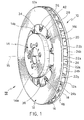
- a disc-brake disc generally indicated 10, comprises a braking band 12 and a bell 14, formed as separate parts.
- the disc shown in the drawings has a rotation axis 15, generally coinciding with the rotation axis of the wheel of the vehicle on which the disc is to be mounted.
- the material used for the production of the bell is selected from metallic materials having good mechanical characteristics such as, for example, steel, hard anodized aluminium alloys, sintered steel, or cast iron.
- the materials used for the production of the braking band are composite materials such as carbon/silicon carbide/silicon (C/SiC/Si) or those with a metal matrix (MMC) such as, for example, aluminium alloys reinforced with ceramic particles such as silicon carbide, alumina, titanium boride, etc.
- C/SiC/Si carbon/silicon carbide/silicon
- MMC metal matrix
- the braking band 12 has the same rotation axis as the disc and comprises braking surfaces 12a for interacting with the pads of a brake caliper, not shown, in order to exert the braking force on the vehicle.
- the braking band 12 is, for example, a ventilated band comprising two plates, indicated 16 and 18, respectively.
- the plates constitute two parallel walls facing one another a certain distance apart, defining a space 20.
- the plate disposed on the same side as the bell 14 is indicated 16 and the plate on the side remote from the bell 14 (when the disc is assembled) is indicated 18.
- the two plates 16 and 18 are connected to one another by fins 22a and 22b which extend between the two plates and define ventilation ducts 24 through the space 20.
- the fins may be formed in accordance with various configurations.
- the fins 22a and 22b and the corresponding ventilation ducts 24 are arranged in a radial direction relative to the rotation axis 15.
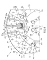
- the braking band 12 has an inner set of teeth, that is, it has a plurality of radial teeth 26 formed around a inner circumferential portion of the braking band, and preferably spaced apart uniformly.
- the teeth alternate with a corresponding number of recesses 28 and preferably extend substantially through the entire thickness of the braking band.
- the teeth 26 of the braking band 12 are constituted by extensions of some of the fins defining the ventilation ducts 24 inside the braking band.
- the fins which extend to form the teeth 26 are indicated 22b, whereas the rest of the fins are indicated 22a.
- the teeth 26 may be constituted by extensions of one fin in every three, thus achieving a configuration in which two consecutive teeth define a portion of band corresponding to three ventilation ducts, although the arrangement may be different.
- each of the fins 22b which are extended to form the teeth 26 of the braking band has a tangential enlargement 30 formed in the vicinity of the actual tooth 26.
- One possible embodiment is shown in the drawings, in which both the tangential dimensions of the teeth and those of the respective fins 22b are smaller than those of the tangential enlargement 30.
- connection between the tangential enlargement and the respective fin is preferably formed gradually, by gradual widening of the ventilation duct in a direction 32 away from the centre, and corresponding to the direction of the air-flow through the ducts 24 during the rotation of the disc 10.
- connection between the two is formed by means of a connecting surface 31 which may be completely outside the ventilation duct, as shown, for example, in Figure 4, or which may also extend inside the duct.
- the teeth 26 comprise sides which have at least one flat portion 26a, preferably the end portion of the tooth in the region of the head of the tooth.
- the expression “sides of a tooth 26” is intended to define the surfaces of the tooth substantially transverse the two plates 16 and 18 and arranged approximately in a radial direction relative to the braking band.
- the flat portion 26a is preferably a continuous axial extension of the connecting surface 31.
- each tooth 26 comprises a flat head 26b, the expression "head of a tooth 26" being intended to define a surface transverse the two plates 16 and 18 and arranged in an approximately tangential direction relative to the braking band.
- a tooth 26 is defined by substantially flat faces 26c parallel to the plates 16 and 18.
- the thickness of the teeth 26, measured in a direction parallel to the rotation axis 15, is slightly less than the thickness of the braking band.
- the faces 26c of the teeth in fact adjoin the braking surfaces of the two plates of the band.
- the ventilation ducts 24 have inlet sections 24a having dimensions which are substantially equal from one duct to another.
- the expression "inlet section 24a of a ventilation duct” is intended to define the cross-section for the air-flow in an area substantially perpendicular to the air-flow and facing the interior of the braking band, that is, towards the rotation axis 15.
- the inlet section 24a of each ventilation duct which is defined by a fin 22b that is extended into a tooth is slightly curved, following the shape of the connecting surface 31.
- the ventilation ducts 24 may have outlet sections 24b having dimensions which are variable from one duct to another.
- the expression "outlet section 24b of a ventilation duct" is intended to define the cross-section for the air-flow air in an area substantially perpendicular to the air-flow and facing outwardly relative to the braking band.
- the dimensions of the outlet sections 24b of the ventilation ducts which are defined on one side by a fin 22b which is extended to form a tooth 26 are equal to one another and larger than those of the outlet sections 24b of the ventilation ducts defined by fins 22a which are not extended to form teeth 26.
- a possible configuration is therefore that shown in Figures 1-4 in which two ventilation ducts 24 with larger outlet sections alternate with one ventilation duct 24 with a smaller outlet section.
- the plate 16 has been partially sectioned to show an example of the configuration of the ventilation ducts according to one possible embodiment of the braking band.
- the ducts defined by two consecutive fins 22a have a cross-section for the air-flow which increases in the direction of the air-flow between the two plates.
- the cross-section for the air-flow increases in the direction of the air-flow both on account of the radial arrangement of the fins and on account of the connection between the tangential enlargement 30 and the fin 22b.
- each recess 28 of the braking band 12 is a portion of a circle having its centre at a point on the rotation axis 15, that is, a circle concentric with the braking band, or a portion of an ellipse having its concave side facing the rotation axis.
- the braking band 12 may comprise holes 33 extending through the thickness of both plates 16 and 18 to improve the efficiency of the cooling of the band.
- the holes preferably have circular cross-sections and are distributed over the entire braking surface of the braking band.
- the bell 14 has the same rotation axis as the assembled disc and as the braking band and advantageously extends in a configuration in which cylindrical portions alternate with flat portions or ring portions coaxial with the axis 15.
- the bell 14 comprises a plate 14a provided with holes for connection to a vehicle wheel hub.
- the axis of the plate 14a coincides with the rotation axis 15 of the bell.
- the outer edge of the plate 14a is substantially a circle from which a cylindrical portion 14b extends parallel to the axis 15.
- the plate 14a and the cylindrical portion 14b are connected continuously in the manner of a beaker with a perforated base.
- the cylindrical portion 14b is connected continuously to an annular portion 14c substantially parallel to the plate 14a.
- the annular portion 14c has, on an outer or peripheral portion thereof, relative to the rotation axis 15, radial teeth 34 alternating with a corresponding number of recesses 36, thus defining a portion for connection to the braking band 12.
- the expression "outer or peripheral portion” is intended to define the portion of the bell radially farthest from the rotation axis 15.
- the radial teeth 34, and hence the respective recesses 36, are preferably spaced apart uniformly and equal in number to the number of radial teeth 26 and of respective recesses 28 of the braking band 12.
- the dimension or, more particularly, the thickness of the radial teeth 34, measured in a direction parallel to the rotation axis 15, corresponds substantially to the thickness of the material of the bell and, in particular, of the annular portion 14c which is connected to the braking band 12. This dimension or thickness is indicated S in Figure 6.
- the bell preferably has a number of walls 38 equal to the number of recesses 36, the walls 38 being arranged in a manner such as to extend the recesses, as described below.
- Each wall 38 projects from the free edge of the respective recess so that the recess is similar to a channel extending axially relative to the disc, without steps or catches.
- each of the recesses 36 is thus defined by the thickness of the bell and by the wall 38, which projects from the bell.
- the length of a recess 36 is indicated L.
- the length L of a recess 36 of the bell is greater than the thickness S of the teeth of the bell, by virtue of the presence of the wall 38 which defines the recess.
- the thickness S of the teeth of the bell is preferably comparable to the thickness S' of the plate 16 which is on the bell side, whereas the length L of the wall defining the recesses 36 is comparable to the total thickness s of the braking band and of the teeth 26.
- each wall 38 at least partially defining a recess 36 of the bell projects in a cantilevered manner relative to a plane 40 containing a front face of each tooth 34 of the bell.
- This plane 40 is shown, for example, in Figure 5 or Figure 6 and, in the assembled disc, is preferably arranged as an extension of the inner plane of a plate of the ventilated band. This is shown, for example, in Figure 6 in which the inner surface of the plate 16 on the bell side is indicated 16a. In fact it can be seen that, when the disc is assembled, the surface 16a of the plate 16 and the plane 40 of the bell constitute theoretical extensions of one another.
- the wall 38 projects from the plane 40 in a cantilevered manner along an axis parallel to the rotation axis 15, preferably in only one direction.
- a possible embodiment is shown in Figure 5 in which the wall 38 projects from the plane 40 in a cantilevered manner, away from the annular portion 14c and from the plate 14a of the bell.
- the shape and dimensions of the wall 38 and of the recess 36 defined thereby are preferably such as to house a tooth 26 of the braking band so that the band and the bell are assembled by a form fit between the teeth of one and the respective recesses of the other, ensuring rotational drive.
- each wall 38 is suitable for driving the braking band during rotation, and extends the corresponding recess 36.
- the wall 38 defining a recess 36 may comprise flat portions 38a suitable for interacting with the sides of a tooth 26 of the band.
- the remaining portion of the wall 38 may be connected with a curved shape or even with flat portions. The wall 38 is thus suitable for driving the braking band 12 during rotation.
- the wall 38 defining a recess 36 of the bell has a radial extent less than that of the adjacent teeth 34, thus leaving an outer portion of the teeth free.
- each tooth 34 of the bell is constituted by a portion of a circle having as its centre a point on the rotation axis 15, that is, a circle concentric with the disc, or by a portion of an ellipse having its concave side facing the rotation axis, that is, of complementary shape to the teeth of the band, suitably spaced therefrom.
- each tooth of the bell extends radially with an extent equal to that between two consecutive teeth of the band which, according to the embodiment of Figure 4, corresponds to three ventilation ducts 24, although the arrangement may be different.
- the coupling between the bell 14 and the braking band 12 is formed, in the first place, by a form fit between the teeth of one and the recesses of the other. This coupling restrains the band on the bell with regard to rotational movements about the axis 15.
- each wall 38 of the bell extends around the respective tooth 26 of the band, substantially along the entire length of the tooth in a direction parallel to the rotation axis 15, at the sides and at the head of the tooth.
- the walls 38 can thus drive the band during rotation by interacting with the respective teeth of the band.
- Each wall 38 of the bell interacts with a single tooth of the band.
- each recess is comparable to the thickness s of the teeth 26 of the braking band, this length and this thickness being measured in a direction substantially parallel to the rotation axis 15.
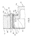
- Figures 5 and 6 show an embodiment of the coupling between the bell and the band.
- Figure 5 corresponds to a section through the disc, taken in a median radial plane with respect to a tooth 26 of the band 12 and to a recess 36 of the bell 14. It can thus be seen from this drawing that the length L of a recess and the thickness s of the tooth 26 of the band are comparable to one another.
- Figure 6 corresponds to a section through the disc, taken in a median radial plane with respect to a recess 28 of the band 12 and a tooth 34 of the bell 14.
- the thickness S of the tooth of the bell is preferably substantially equal to the thickness S' of the plate 16 which is on the same side as the bell 14 and less than the length L of the wall 38.
- this drawing shows that, in the coupling between the bell and the band, the plate 16 and the teeth 34 of the bell constitute theoretical extensions of one another, and the inlet sections 24a of the ventilation ducts affected by the angular extent of a tooth 34 of the bell remain completely free.
- the tangential restraint between the band and the bell is achieved by a toothed coupling with clearance between the teeth 34 of the bell 14 and the teeth 26 of the band 12.
- an insert element 42 capable of plastic or elastic deformation is advantageously provided between the wall 38 defining a recess 36 of the bell and the respective tooth 26 of the braking band to ensure a substantially uniform distribution of the loads transmitted by a braking operation.
- material capable of plastic or elastic deformation is intended to define a material which, when subject to a load such as, for example, the braking force acting on the band, undergoes elastoplastic or elastic deformation.
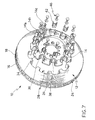
- Each insert element 42 is constituted by a plate-shaped element bent substantially to a "U"-shape as shown, for example, in Figure 4, or to a "W"-shape, as shown in Figure 7.
- Each wall 38, and consequently also each recess 36 of the bell, and possibly the respective insert element 42, is shaped in a manner such as to define a seat 44 for housing axial restraining means 46 operating between the bell and the braking band.
- the seat for housing the axial restraining means 46 is provided by virtue of the presence of a continuous wall 38 which extends around a tooth of the band at the sides and at the head. The wall 38 thus performs both the task of bringing about rotation of the band with the bell, and that of defining a seat for housing the axial restraining means.
- the seat 44 is defined between the wall 38/insert element 42 and the respective tooth 26 of the ventilated braking band.
- the seat 44 is defined between the wall 38 and the insert element 42/tooth 26 of the braking band.
- the axial restraining means 46 comprise a plurality of pins 48 each housed in one of the housing seats 44.
- Each pin 48 has a head 50 for abutting, preferably, the free end of the wall 38 which corresponds to the end farthest from the plate 14a for fixing to the vehicle wheel hub, that is, on the side remote from the bell.
- the pin 48 comprises a notch 52 for housing a retaining ring 54.
- resilient means 56 are provided, acting in a direction substantially parallel to the rotation axis 15 and operating to restrain the band axially relative to the bell.
- These resilient means 56 may, for example, be constituted by opposed crinkle washers or Belleville washers 58 fitted between two washers 60 and restrained between the bell/band and the retaining ring 54.
- Figure 2 shows an example of the assembly stage in which the bell is mounted on the band by coupling of the respective teeth/recesses.
- the pins 48 are inserted in the seats 44 from the side on which the plate 18 is disposed, in a direction substantially parallel to the rotation axis 15.
- the head 50 abuts the free surface of the wall 38 and the face 26c of the tooth 26 on the side remote from the bell.
- a washer 60, two Belleville washers 58 arranged with their concave sides facing in opposite directions, a washer 60, and the retaining ring 54 are fitted in sequence, the retaining ring 54 being locked in the notch 52.
- the unit thus assembled is shown in the section of Figure 5.
- the toothed coupling ensures tangential restraint between the band and the bell, whilst the pins 48, which are advantageously housed between the wall 38 and the respective tooth, ensure axial restraint between these two. Tangential restraint is ensured by the interaction between the teeth of the band and the respective recesses of the bell which advantageously come into contact substantially along the entire depth L of the recess (or thickness s of the tooth of the band).
- the elastoplastic or elastic deformation of these elements constitutes a compliance of the connection between the teeth of the bell and of the braking band which enables all of the teeth to be brought into a working condition in which the load is distributed uniformly.
- the insert elements are arranged between the teeth of the bell and of the braking band without preloading, upon the application of the load, in a first stage, the clearance present between the teeth will be taken up and the band will rotate relative to the bell without transmitting the load.
- the insert element will come to bear on the tooth of the bell and will start to deform resiliently under load.
- the insert elements are arranged between the teeth of the bell and of the band with preloading, for example, because the insert elements are fitted between the teeth of the bell and of the band with a predetermined interference (or force fit) which brings about preloading thereof.
- the differences in load between the various teeth will be given by the differences in the preloading of the various inserts due to the manufacturing tolerances of the distances between the facing teeth. The largest of these preloading differences will correspond to the maximum load difference present between the teeth at the same moment.
- the tooth which had the greatest preloading will be that which is most loaded, purely by a value equal to the greater extent of its preloading.
- This difference in preloading which, in comparison with the overall load, will be equal to only a small fraction thereof, will be the sole non-uniformity in the distribution of the load on the teeth of the bell and of the braking band.
- the bell comprises a plurality of radial teeth alternating with respective recesses in which each of the recesses is defined by at least one wall and has a length greater than the thickness of the teeth, it is possible to use a ventilated braking band without the bell obstructing the ventilation ducts.
- two adjacent walls 38 and the respective plane 40 substantially define an air-inlet duct which favours the channelling of the air into the ventilation ducts of the band which are affected by the angular extent of a tooth of the bell.
- the tangential restraint between the bell and the band makes maximum use of the thickness S of the teeth of the bell, rendering it substantially equal to the thickness S' of the respective plate which, in the embodiments illustrated, is the plate 16 on the bell side.
- the configuration as described above also permits the formation of a substantially continuous ventilation duct between the bell and the band, without steps, by virtue of the fact that the plane 40 and the inner surface of the respective plate (that is, the plate 16 on the bell side) form extensions of one another when the disc is assembled.
- the above-mentioned configuration of the bell not only eliminates obstructions to the air-flow, but also directs the air-flow, optimizing the quantity of air passing through the ventilation ducts and avoiding tortuous paths thereof.
- the advantageous coupling between the bell according to the present invention and a ventilated band produces the effect of an extension of the ventilation ducts towards the interior of the bell, utilizing the channelling offered by two adjacent walls 38 and keeping the path of the air substantially perpendicular to the axis 15.
- the bell and the disc according to the present invention satisfy the above-mentioned need to limit the weight and the complexity of the structure and optionally to optimize cooling efficiency, whilst maintaining good resistance to wear and to thermal/mechanical stresses which is ensured by the presence of a band and a bell made of different materials and connected without radial restraints.
- the foregoing is achieved without the need for any structural, manufacturing, or functional complications, by taking advantage of the versatility of the bell and, in particular, of its material, to produce a shape as described above.
- the bell can in fact be made by precision casting, for example, of stainless steel or of pressed or sintered steel, or of pressed or cast light alloys.
- a wall 38 which extends the length of the respective recess of the bell substantially to the extent of the respective tooth of the band enables the loads to be distributed over a fairly large surface, keeping the contact pressures low.
- a continuous wall which extends around the respective tooth of the band at the sides and at the head enables the structure to be optimized, defining a seat for the axial restraining means between the bell and the band.
- the structure of the bell is considerably lightened whilst ensuring optimal contact between the band and the bell with regard to the tangential restraint between these two.
- the above-mentioned configuration also enables the structure to be optimized whilst avoiding further machining and bringing together in the wall 38 both the function of defining a recess of the bell and driving the band during rotation, and that of housing the axial restraining means between the band and the bell.
- each wall 38 which project relative to the teeth of the bell or to the plane 40, and which may be chamfered, preferably towards the inside of the respective recess, and may have a shape complementary to corresponding profiles of the tangential enlargement of the fin of the braking band.
- the wall 38 defining a recess 36 of the bell forms an extension of the tangential enlargement 30 of the fin 22b of the band, thus defining a substantially continuous wall for the flow of the air along the ducts 24.
- axial restraint may be achieved differently, for example, by means of bolts housed in the seats 44.
Landscapes
- Engineering & Computer Science (AREA)
- General Engineering & Computer Science (AREA)
- Mechanical Engineering (AREA)
- Braking Arrangements (AREA)
Claims (38)
- Scheibenbremsglocke (14), geeignet für die Verbindung mit einem Bremsband (12), wobei die Glocke eine Drehachse (15) aufweist und eine Vielzahl von radialen Zähnen (34) umfasst, die entlang einem Außen- oder Umfangsabschnitt der Glocke ausgebildet sind und sich mit entsprechenden Aussparungen (36) abwechseln, die zur Aufnahme radialer Zähne des Bremsbands geeignet sind, wobei die Glocke eine Platte (14a) umfasst, die mit Löchern für die Verbindung mit einer Radnabe eines Fahrzeugs versehen sind, einen zylindrischen Abschnitt (14b), der durchgehend von einer äußeren Kante der Platte (14a) parallel zu der Drehachse (15) herausragt, einen ringförmigen Abschnitt (14c), der durchgehend aus dem zylindrischen Abschnitt (14b) hervorragt und der in einem Außen- oder Umfangsabschnitt davon die radialen Zähne (34) aufweist, die sich mit den Aussparungen (36) abwechseln, dadurch gekennzeichnet, dass die Glocke des Weiteren wenigstens eine Wand (38) umfasst, die aus dem ringförmigen Abschnitt (14c) ausladend hervorragt, und die geeignet ist, das Bremsband anzutreiben, wobei die Wand (38) wenigstens eine der Aussparungen (36) so verlängert, dass die wenigstens eine Aussparung eine Länge (L) aufweist, die größer als eine Dicke (S) der radialen Zähne (34) der Glocke ist, wobei die Länge (L) und die Dicke (S) in einer Richtung gemessen werden, die im Wesentlichen parallel zu der Drehachse (15) verläuft.
- Scheibenbremsglocke (14) gemäß Anspruch 1, wobei die wenigstens eine Wand (38) aus dem ringförmigen. Abschnitt (14c) ausladend in einer Richtung hervorragt, die parallel zu der Drehachse (15) der Glocke verläuft.
- Scheibenbremsglocke (14) gemäß Anspruch 1 oder Anspruch 2, wobei die Wand (38) aus der freien Kante der entsprechenden Aussparung hervorragt, und die Aussparungen (36) frei von axialen Arretierungen sind, die das Bremsband einseitig in Bezug auf die im Wesentlichen zu der Achse (15) parallelen Bewegungen feststellen könnten.
- Scheibenbremsglocke (14) gemäß einem der vorhergehenden Ansprüche, geeignet für die Verbindung mit einem belüfteten Bremsband (12).
- Scheibenbremsglocke (14) gemäß einem der vorhergehenden Ansprüche, wobei jede Aussparung (36) wenigstens durch eine durchgehende, im Wesentlichen "U"-förmige Wand (38) definiert ist.
- Scheibenbremsglocke (14) gemäß Anspruch 5, wobei sich die Wand (38) um die Seiten und den Kopf des entsprechenden Zahns des Bremsbands erstreckt.
- Scheibenbremsglocke (14) gemäß einem der vorhergehenden Ansprüche, wobei jede Wand (38), die wenigstens teilweise eine Aussparung (36) definiert, sich in Bezug auf eine Ebene (40) ausladend erstreckt, die eine Vorderseite jedes Zahns (34) definiert.
- Scheibenbremsglocke (14) gemäß Anspruch 7, wobei sich die Wand (38) in nur eine Richtung in Bezug auf die Ebene (40) erstreckt, die eine Vorderseite jedes Zahns (34) enthält.
- Scheibenbremsglocke (14) gemäß einem oder mehreren der vorhergehenden Ansprüche, wobei die Wand (38) einen Sitz (44) zum Aufnehmen von axialen Haltemitteln (46) zwischen der Glocke und einem Bremsband (12) definiert.
- Scheibenbremsglocke (14) gemäß einem oder mehreren der vorhergehenden Ansprüche, wobei die Wand (38) eine radiale Ausdehnung aufweist, die geringer ist als diejenige der benachbarten Zähne (34), wodurch ein äußerer Abschnitt der Zähne frei bleibt.
- Scheibenbremsglocke (14) gemäß einem oder mehreren der vorhergehenden Ansprüche, wobei die Enden der definierenden Wand (38), die von den Zähnen der Glocke herausragen, abgefast sind.
- Scheibenbremsglocke (14) gemäß Anspruch 11, wobei die Enden der definierenden Wand (38), die von den Zähnen (34) der Glocke herausragen, zur Innenseite der entsprechenden Aussparungen (36) hin abgefast sind.
- Scheibenbremsglocke (14) gemäß einem oder mehreren der vorhergehenden Ansprüche, wobei die definierende Wand (38) jeder Aussparung (36) integral mit der Glocke ausgeformt ist.
- Scheibenbremsglocke (14) gemäß einem oder mehreren der vorhergehenden Ansprüche, wobei das äußere Profil jedes Zahns (34) der Glocke ein Abschnitt eines mit der Glocke konzentrischen Kreises ist.
- Scheibenbremsglocke (14) gemäß einem oder mehreren der Ansprüche 1 bis 13, wobei das äußere Profil jedes Zahns (34) der Glocke ein Abschnitt einer Ellipse ist, deren konkave Seite der Drehachse (15) der Glocke zugewandt ist.
- Scheibenbremsscheibe (10) umfassend:wobei das Bremsband (12) und die Glocke (14) eine Drehachse (15) aufweisen und miteinander wenigstens durch einen Formschluss zwischen den Zähnen (26, 34) des einen und den entsprechenden Aussparungen (28, 36) der anderen verbunden sind.ein Bremsband (12), das mit einer Vielzahl von radialen Zähnen (26) versehen ist, die entlang einem inneren Abschnitt des Bremsbands ausgebildet sind und sich mit entsprechenden Aussparungen (28) abwechseln, und eine Scheibenbremsglocke (14) gemäß Anspruch 1,
- Scheibenbremsscheibe (10) gemäß Anspruch 16, wobei die Wand (38) der Glocke (14) so ausgeformt ist, dass sie mit dem Zahn (26) des Bremsbands (12) einen Sitz (44) zum Aufnehmen von axialen Haltemitteln (46) definiert, die zwischen der Glocke (14) und dem belüfteten Band (12) wirken.
- Scheibenbremsscheibe (10) gemäß Anspruch 16, wobei ein Einsatzelement (42), das plastisch oder elastisch verformbar ist, in die Aussparung (36) zwischen der Wand (38) der Glocke (14) und dem entsprechenden Zahn (26) des Bremsbands (12) eingepasst ist, um eine im Wesentlichen gleichförmige Verteilung der Belastungen sicherzustellen, die von einem Bremsvorgang übertragen werden.
- Scheibenbremsscheibe (10) gemäß den Ansprüchen 17 und 18, wobei die Wand (38) der Glocke (14) und das Einsatzelement (42) so geformt sind, dass sie einen Sitz (44) zum Aufnehmen von axialen Haltemitteln (46) definieren, die zwischen der Glocke (14) und dem belüfteten Band (12) wirken.
- Scheibenbremsscheibe (10) gemäß Anspruch 19, wobei die Wand (38) der Glocke (14) und das Einsatzelement (42) im Wesentlichen "Ú"-förmig sind, wobei sie mit dem Zahn (26) des Bremsbands (12) einen Sitz (44) zum Aufnehmen von axialen Haltemitteln (46) definieren, die zwischen der Glocke (14) und dem belüfteten Band (12) wirken.
- Scheibenbremsscheibe (10) gemäß Anspruch 19, wobei die Wand (38) der Glocke (14) im Wesentlichen "U"-förmig ist, und wobei das Einsatzelement (42) im Wesentlichen "W"-förmig ist und mit der Wand (38) der entsprechenden Aussparung (36) der Glocke (14) einen Sitz (44) zum Aufnehmen von axialen Haltemitteln (46) definiert, die zwischen der Glocke (14) und dem belüfteten Band (12) wirken.
- Scheibenbremsscheibe (10) gemäß Anspruch 17 oder Anspruch 19, wobei die axialen Haltemittel (46) eine Vielzahl von Stiften (48) umfassen, von denen jeder in einer der aufnehmenden Sitzn (44) aufgenommen ist.
- Scheibenbremsscheibe (10) gemäß irgendeinem der Ansprüche 16 bis 22, wobei sich die Wand (38) einer Aussparung (36) der Glocke (14) ausladend in Bezug auf eine Ebene (40) erstreckt, die eine Vorderseite jedes Zahns (34) der Glocke definiert, beginnend von einer freien Kante der Aussparung aus.
- Scheibenbremsscheibe (10) gemäß Anspruch 23, wobei sich die Wand (38) einer Aussparung (36) der Glocke (14) ausladend entlang einer Achse erstreckt, die parallel zu der Drehachse (15) verläuft.
- Scheibenbremsscheibe (10) gemäß Anspruch 23 oder Anspruch 24, wobei die Wand (38) einer Aussparung (36) der Glocke (14) sich nur in eine Richtung in Bezug auf die Ebene (40) erstreckt, die eine Vorderseite jedes Zahns (34) der Glocke definiert.
- Scheibenbremsscheibe (10) gemäß irgendeinem der Ansprüche 23 bis 25, wobei die Ebene (40), die eine Vorderseite jedes Zahns (34) der Glocke definiert, als eine theoretische Verlängerung einer inneren Oberfläche (16a) einer Platte (16) eines belüfteten Bremsbands (12) angeordnet ist.
- Scheibenbremsscheibe (10) gemäß Anspruch 26, wobei die Dicke (S) der Zähne (34) der Glocke (14) im Wesentlichen gleich der Dicke (S') der Platte (16) ist, die auf der gleichen Seite wie die Glocke (14) angeordnet ist, wobei die Dicken (S, S') in einer Richtung gemessen werden, die im Wesentlichen parallel zu der Drehachse (15) verlaufen.
- Scheibenbremsscheibe (10) gemäß irgendeinem der Ansprüche 16 bis 27, wobei die Aussparungen (36) der Glocke (14) eine Länge (L) aufweisen, die größer als die Dicke (s) der Zähne (26) des Bremsbands (12) ist, wobei die Länge (L) und die Dicke (s) in einer Richtung gemessen werden, die im Wesentlichen parallel zu der Drehachse (15) verläuft.
- Scheibenbremsscheibe (10) gemäß irgendeinem der Ansprüche 16 bis 28, wobei elastische Mittel (56) zwischen dem Bremsband (12) und der Glocke (14) angeordnet vorgesehen sind und in einer Richtung wirken, die parallel zu der Drehachse (15) verläuft.
- Scheibenbremsscheibe (10) gemäß Anspruch 29, wobei die elastischen Mittel (56) zwei Belleville-Scheiben oder Wellscheiben (58) umfassen, die mit ihren einander entgegengesetzten konkaven Seiten auf einem Stift (48) befestigt sind und Mittel (46) zum Halten des Bremsbands (12) in axialem Bezug zur Glocke (14) definieren.
- Scheibenbremsscheibe (10) gemäß irgendeinem der Ansprüche 16 bis 30, wobei die Zähne (26) des Bremsbands (12) durch Verlängerungen von Rippen (22b) ausgebildet sind, die Lüftungskanäle (24) in dem belüfteten Bremsband definieren.
- Scheibenbremsscheibe (10) gemäß Anspruch 31, wobei jede Rippe (22b), die verlängert ist, um einen Zahn (26) des Bremsbands (12) auszubilden, eine tangentiale Vergrößerung (30) in der Nähe des eigentlichen Zahns aufweist.
- Scheibenbremsscheibe (10) gemäß Anspruch 32, wobei die Wand (38) einer Aussparung (36) der Glocke (14) eine Verlängerung der tangentialen Vergrößerung ausbildet, um eine im Wesentlichen durchgehende Wand für das Fließen der Luft zu definieren.
- Scheibenbremsscheibe (10) gemäß Anspruch 33, wobei die Enden der Wand (38), die von den Zähnen (34) der Glocke (14) herausragen, abgefast sind und eine komplementäre Form zu den entsprechenden Profilen der tangentialen Vergrößerung (30) der Rippe (22b) des Bremsbands (12) aufweisen.
- Scheibenbremsscheibe (10) gemäß einem oder mehreren der Ansprüche 16 bis 34, wobei die Wand (38) einer Aussparung (36) der Glocke (14) eine radiale Ausdehnung aufweist, die geringer ist als diejenige der Zähne (34) der Glocke.
- Scheibenbremsscheibe (10) gemäß irgendeinem der Ansprüche 16 bis 35, wobei die äußeren Profile der Zähne (34) der Glocke (14) und die inneren Profile der Aussparungen (28) des Bremsbands (12) Abschnitte von Kreisen sind, die mit der Scheibe konzentrisch sind.
- Scheibenbremsscheibe (10) gemäß irgendeinem der Ansprüche 16 bis 35, wobei die äußeren Profile der Zähne (34) der Glocke (14) und die inneren Profile der Aussparungen (28) des Bremsbands (12) Abschnitte von Ellipsen sind, deren konkave Seiten zur Drehachse (15) zugewandt sind.
- Scheibenbremsscheibe (10) gemäß irgendeinem der Ansprüche 16 bis 37, wobei das belüftete Bremsband (12) zwei Platten (16, 18) umfasst, die mit Löchern (33) versehen sind, die sich durch die Dicke der Platte erstrecken.
Applications Claiming Priority (1)
| Application Number | Priority Date | Filing Date | Title |
|---|---|---|---|
| PCT/IT2002/000257 WO2003089802A1 (en) | 2002-04-22 | 2002-04-22 | Bell for braking disc and disc for a disc brake |
Publications (2)
| Publication Number | Publication Date |
|---|---|
| EP1379794A1 EP1379794A1 (de) | 2004-01-14 |
| EP1379794B1 true EP1379794B1 (de) | 2005-03-16 |
Family
ID=29227546
Family Applications (1)
| Application Number | Title | Priority Date | Filing Date |
|---|---|---|---|
| EP02800498A Expired - Lifetime EP1379794B1 (de) | 2002-04-22 | 2002-04-22 | Topf für eine bremsscheibe sowie bremsscheibe für eine scheibenbremse |
Country Status (5)
| Country | Link |
|---|---|
| EP (1) | EP1379794B1 (de) |
| AT (1) | ATE291181T1 (de) |
| AU (1) | AU2002307743A1 (de) |
| DE (1) | DE60203273D1 (de) |
| WO (1) | WO2003089802A1 (de) |
Families Citing this family (10)
| Publication number | Priority date | Publication date | Assignee | Title |
|---|---|---|---|---|
| US7436914B2 (en) | 2005-07-11 | 2008-10-14 | Mediatek Incorporation | Methods and apparatus for providing television signals |
| WO2007101918A1 (fr) * | 2006-03-08 | 2007-09-13 | Sa Beringer | Disque de frein pour vehicule comprenant une piste de freinage rendue solidaire, avec capacite de deplacement, d'une frette montee sur une roue |
| DE102012102064A1 (de) * | 2012-03-12 | 2013-09-12 | PE Automotive GmbH & Co. KG | Verschleißblech für eine Bremsscheibe |
| DE102015006077A1 (de) * | 2015-05-09 | 2016-11-10 | Daimler Ag | Kraftfahrzeug |
| IT201700079216A1 (it) * | 2017-07-13 | 2019-01-13 | T M Tecnologie Mecc | Disco freno flottante. |
| IT201700097892A1 (it) | 2017-08-31 | 2019-03-03 | Freni Brembo Spa | Disco freno per freno a disco |
| US10830295B2 (en) | 2018-07-20 | 2020-11-10 | Bendix Spicer Foundation Brake Llc | Brake disc mounting arrangement |
| US10704628B2 (en) | 2018-07-20 | 2020-07-07 | Bendix Spicer Foundation Brake Llc | Brake disc mounting arrangement |
| US10837509B2 (en) | 2018-07-20 | 2020-11-17 | Bendix Spicer Foundation Brake Llc | Brake disc mounting arrangement |
| EP3899310B1 (de) | 2018-12-20 | 2023-04-19 | Brembo S.p.A. | Scheibenanordnung einer scheibenbremse |
Family Cites Families (3)
| Publication number | Priority date | Publication date | Assignee | Title |
|---|---|---|---|---|
| DE19628331A1 (de) * | 1996-07-13 | 1998-01-15 | Teves Gmbh Alfred | Bremsscheibeneinheit |
| FR2799520B1 (fr) * | 1999-10-08 | 2002-01-25 | Messier Bugatti | Dispositif de fixaion axiale d'un disque ventile de freinage sur le moyeu d'une roue d'un vehicule automobile |
| JP2004526906A (ja) | 2000-06-28 | 2004-09-02 | フレニ・ブレンボ エス・ピー・エー | 摩耗及び熱−機械応力に対して高耐性を有するブレーキディスク |
-
2002
- 2002-04-22 EP EP02800498A patent/EP1379794B1/de not_active Expired - Lifetime
- 2002-04-22 WO PCT/IT2002/000257 patent/WO2003089802A1/en not_active Ceased
- 2002-04-22 AU AU2002307743A patent/AU2002307743A1/en not_active Abandoned
- 2002-04-22 AT AT02800498T patent/ATE291181T1/de not_active IP Right Cessation
- 2002-04-22 DE DE60203273T patent/DE60203273D1/de not_active Expired - Fee Related
Also Published As
| Publication number | Publication date |
|---|---|
| AU2002307743A1 (en) | 2003-11-03 |
| EP1379794A1 (de) | 2004-01-14 |
| WO2003089802A1 (en) | 2003-10-30 |
| DE60203273D1 (de) | 2005-04-21 |
| ATE291181T1 (de) | 2005-04-15 |
Similar Documents
| Publication | Publication Date | Title |
|---|---|---|
| EP1395761B1 (de) | Scheibe für eine luftgekühlte scheibenbremse | |
| US4844206A (en) | Dual disk brake | |
| EP1309806B1 (de) | Scheibenbremse mit hohem widerstandsvermögen gegen verschleiss und thermo-mechanische beanspruchung | |
| US20070199778A1 (en) | Vented disc brake rotor | |
| US8336682B2 (en) | Ventilated brake disk and method | |
| CN102341612A (zh) | 制动盘 | |
| EP1228322B1 (de) | Bremsscheibe für eine fahrzeug-scheibenbremse | |
| EP1379794A1 (de) | Topf für eine bremsscheibe sowie bremsscheibe für eine scheibenbremse | |
| KR101964125B1 (ko) | 브레이크 디스크 | |
| EP1352179A1 (de) | Bremsband und scheibe für eine scheibenbremse | |
| CN112469919A (zh) | 制动盘安装布置 | |
| EP1327085B1 (de) | Bremsscheibe | |
| US6135248A (en) | Brake disk | |
| CN112469916A (zh) | 制动盘安装布置 | |
| JP2009513909A (ja) | 駐車ブレーキ | |
| JP5879032B2 (ja) | ディスクブレーキ | |
| JP7664159B2 (ja) | ディスクブレーキのディスクアセンブリ | |
| EP1499814B2 (de) | Bremsbelag für scheibenbremse | |
| US20240384768A1 (en) | Friction damping ring for a disc brake rotor and rotor employing the same | |
| JP7587515B2 (ja) | 車両用ディスクブレーキ | |
| EP2740961B1 (de) | Verbindungseinrichtung für Scheibenbremse | |
| US20080142314A1 (en) | Methods and apparatus to connect a brake disc to a brake | |
| JP4249065B2 (ja) | ディスクブレーキ | |
| GB2343721A (en) | Friction disc for a clutch or disc brake | |
| JP4757791B2 (ja) | ディスクブレーキのモノブロックキャリパおよびその製造方法 |
Legal Events
| Date | Code | Title | Description |
|---|---|---|---|
| PUAI | Public reference made under article 153(3) epc to a published international application that has entered the european phase |
Free format text: ORIGINAL CODE: 0009012 |
|
| 17P | Request for examination filed |
Effective date: 20030314 |
|
| AK | Designated contracting states |
Kind code of ref document: A1 Designated state(s): AT BE CH CY DE DK ES FI FR GB GR IE IT LI LU MC NL PT SE TR |
|
| AX | Request for extension of the european patent |
Extension state: AL LT LV MK RO SI |
|
| 17Q | First examination report despatched |
Effective date: 20040206 |
|
| GRAP | Despatch of communication of intention to grant a patent |
Free format text: ORIGINAL CODE: EPIDOSNIGR1 |
|
| GRAS | Grant fee paid |
Free format text: ORIGINAL CODE: EPIDOSNIGR3 |
|
| GRAA | (expected) grant |
Free format text: ORIGINAL CODE: 0009210 |
|
| RIN1 | Information on inventor provided before grant (corrected) |
Inventor name: PACCHIANA, GIOVANNI, PAOLO Inventor name: LORENZO, SILVIO |
|
| AK | Designated contracting states |
Kind code of ref document: B1 Designated state(s): AT BE CH CY DE DK ES FI FR GB GR IE IT LI LU MC NL PT SE TR |
|
| AX | Request for extension of the european patent |
Extension state: SI |
|
| PG25 | Lapsed in a contracting state [announced via postgrant information from national office to epo] |
Ref country code: NL Free format text: LAPSE BECAUSE OF FAILURE TO SUBMIT A TRANSLATION OF THE DESCRIPTION OR TO PAY THE FEE WITHIN THE PRESCRIBED TIME-LIMIT Effective date: 20050316 Ref country code: ES Free format text: LAPSE BECAUSE OF FAILURE TO SUBMIT A TRANSLATION OF THE DESCRIPTION OR TO PAY THE FEE WITHIN THE PRESCRIBED TIME-LIMIT Effective date: 20050316 Ref country code: AT Free format text: LAPSE BECAUSE OF FAILURE TO SUBMIT A TRANSLATION OF THE DESCRIPTION OR TO PAY THE FEE WITHIN THE PRESCRIBED TIME-LIMIT Effective date: 20050316 Ref country code: TR Free format text: LAPSE BECAUSE OF FAILURE TO SUBMIT A TRANSLATION OF THE DESCRIPTION OR TO PAY THE FEE WITHIN THE PRESCRIBED TIME-LIMIT Effective date: 20050316 Ref country code: FI Free format text: LAPSE BECAUSE OF FAILURE TO SUBMIT A TRANSLATION OF THE DESCRIPTION OR TO PAY THE FEE WITHIN THE PRESCRIBED TIME-LIMIT Effective date: 20050316 Ref country code: LI Free format text: LAPSE BECAUSE OF FAILURE TO SUBMIT A TRANSLATION OF THE DESCRIPTION OR TO PAY THE FEE WITHIN THE PRESCRIBED TIME-LIMIT Effective date: 20050316 Ref country code: CH Free format text: LAPSE BECAUSE OF FAILURE TO SUBMIT A TRANSLATION OF THE DESCRIPTION OR TO PAY THE FEE WITHIN THE PRESCRIBED TIME-LIMIT Effective date: 20050316 Ref country code: BE Free format text: LAPSE BECAUSE OF FAILURE TO SUBMIT A TRANSLATION OF THE DESCRIPTION OR TO PAY THE FEE WITHIN THE PRESCRIBED TIME-LIMIT Effective date: 20050316 |
|
| REG | Reference to a national code |
Ref country code: GB Ref legal event code: FG4D |
|
| REG | Reference to a national code |
Ref country code: CH Ref legal event code: EP |
|
| REG | Reference to a national code |
Ref country code: IE Ref legal event code: FG4D |
|
| REF | Corresponds to: |
Ref document number: 60203273 Country of ref document: DE Date of ref document: 20050421 Kind code of ref document: P |
|
| PG25 | Lapsed in a contracting state [announced via postgrant information from national office to epo] |
Ref country code: IE Free format text: LAPSE BECAUSE OF NON-PAYMENT OF DUE FEES Effective date: 20050422 Ref country code: CY Free format text: LAPSE BECAUSE OF FAILURE TO SUBMIT A TRANSLATION OF THE DESCRIPTION OR TO PAY THE FEE WITHIN THE PRESCRIBED TIME-LIMIT Effective date: 20050422 Ref country code: LU Free format text: LAPSE BECAUSE OF NON-PAYMENT OF DUE FEES Effective date: 20050422 |
|
| PG25 | Lapsed in a contracting state [announced via postgrant information from national office to epo] |
Ref country code: MC Free format text: LAPSE BECAUSE OF NON-PAYMENT OF DUE FEES Effective date: 20050430 |
|
| PG25 | Lapsed in a contracting state [announced via postgrant information from national office to epo] |
Ref country code: GR Free format text: LAPSE BECAUSE OF FAILURE TO SUBMIT A TRANSLATION OF THE DESCRIPTION OR TO PAY THE FEE WITHIN THE PRESCRIBED TIME-LIMIT Effective date: 20050616 Ref country code: DK Free format text: LAPSE BECAUSE OF FAILURE TO SUBMIT A TRANSLATION OF THE DESCRIPTION OR TO PAY THE FEE WITHIN THE PRESCRIBED TIME-LIMIT Effective date: 20050616 |
|
| NLV1 | Nl: lapsed or annulled due to failure to fulfill the requirements of art. 29p and 29m of the patents act | ||
| PG25 | Lapsed in a contracting state [announced via postgrant information from national office to epo] |
Ref country code: PT Free format text: LAPSE BECAUSE OF FAILURE TO SUBMIT A TRANSLATION OF THE DESCRIPTION OR TO PAY THE FEE WITHIN THE PRESCRIBED TIME-LIMIT Effective date: 20050907 |
|
| REG | Reference to a national code |
Ref country code: CH Ref legal event code: PL |
|
| PG25 | Lapsed in a contracting state [announced via postgrant information from national office to epo] |
Ref country code: DE Free format text: LAPSE BECAUSE OF NON-PAYMENT OF DUE FEES Effective date: 20051101 |
|
| PLBE | No opposition filed within time limit |
Free format text: ORIGINAL CODE: 0009261 |
|
| STAA | Information on the status of an ep patent application or granted ep patent |
Free format text: STATUS: NO OPPOSITION FILED WITHIN TIME LIMIT |
|
| 26N | No opposition filed |
Effective date: 20051219 |
|
| EN | Fr: translation not filed | ||
| PG25 | Lapsed in a contracting state [announced via postgrant information from national office to epo] |
Ref country code: SE Free format text: LAPSE BECAUSE OF FAILURE TO SUBMIT A TRANSLATION OF THE DESCRIPTION OR TO PAY THE FEE WITHIN THE PRESCRIBED TIME-LIMIT Effective date: 20050616 |
|
| PG25 | Lapsed in a contracting state [announced via postgrant information from national office to epo] |
Ref country code: FR Free format text: LAPSE BECAUSE OF NON-PAYMENT OF DUE FEES Effective date: 20050430 |
|
| PG25 | Lapsed in a contracting state [announced via postgrant information from national office to epo] |
Ref country code: FR Free format text: LAPSE BECAUSE OF NON-PAYMENT OF DUE FEES Effective date: 20050316 |
|
| PGFP | Annual fee paid to national office [announced via postgrant information from national office to epo] |
Ref country code: GB Payment date: 20120419 Year of fee payment: 11 |
|
| PGFP | Annual fee paid to national office [announced via postgrant information from national office to epo] |
Ref country code: IT Payment date: 20120416 Year of fee payment: 11 |
|
| GBPC | Gb: european patent ceased through non-payment of renewal fee |
Effective date: 20130422 |
|
| PG25 | Lapsed in a contracting state [announced via postgrant information from national office to epo] |
Ref country code: GB Free format text: LAPSE BECAUSE OF NON-PAYMENT OF DUE FEES Effective date: 20130422 |
|
| PG25 | Lapsed in a contracting state [announced via postgrant information from national office to epo] |
Ref country code: IT Free format text: LAPSE BECAUSE OF NON-PAYMENT OF DUE FEES Effective date: 20130422 |